The Smell of Molten Projects in the Morning

Ed Nisley's Blog: Shop notes, electronics, firmware, machinery, 3D printing, laser cuttery, and curiosities. Contents: 100% human thinking, 0% AI slop.

Tag: M2

Using and tweaking a Makergear M2 3D printer

  • Tek Circuit Computer: 3D Printed Cursor Milling Fixture

    Tek Circuit Computer: 3D Printed Cursor Milling Fixture

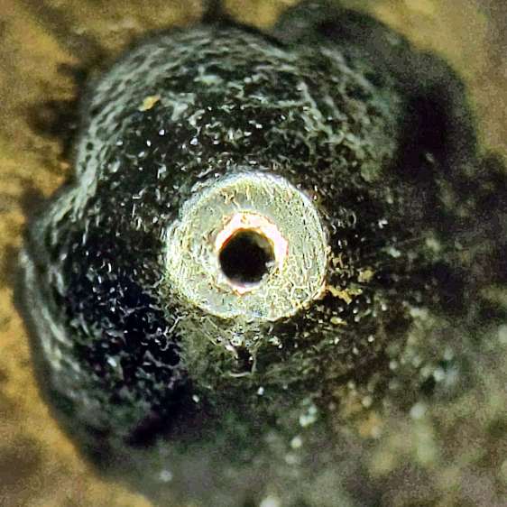
    The original Tektronix Circuit Computer cursor was probably die-cut from a larger sheet carrying pre-printed hairlines:

    Tek CC - genuine - detail
    Tek CC – genuine – detail

    Machining a punch-and-die setup lies well beyond my capabilities, particularly given the ahem anticipated volume, so milling seems the only practical way to produce a few cursors.

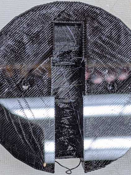
    Attaching a cursor blank to a fixture with sticky tape showed that the general idea worked reasonably well:

    Tek CC - Cursor blank on fixture
    Tek CC – Cursor blank on fixture

    However, the tape didn’t have quite enough griptivity to hold the edges completely flat against milling forces (a downcut bit might have worked better) and I found myself chasing the cutter with a screwdriver to hold the cursor in place. Worse, the tape’s powerful attraction to swarf made it a single-use item.

    Some tinkering showed a single screw in the (pre-drilled) pivot hole, without adhesive underneath, lacked enough oomph to keep the far end of the cursor in place, which meant I had to think about how to hold it down with real clamps.

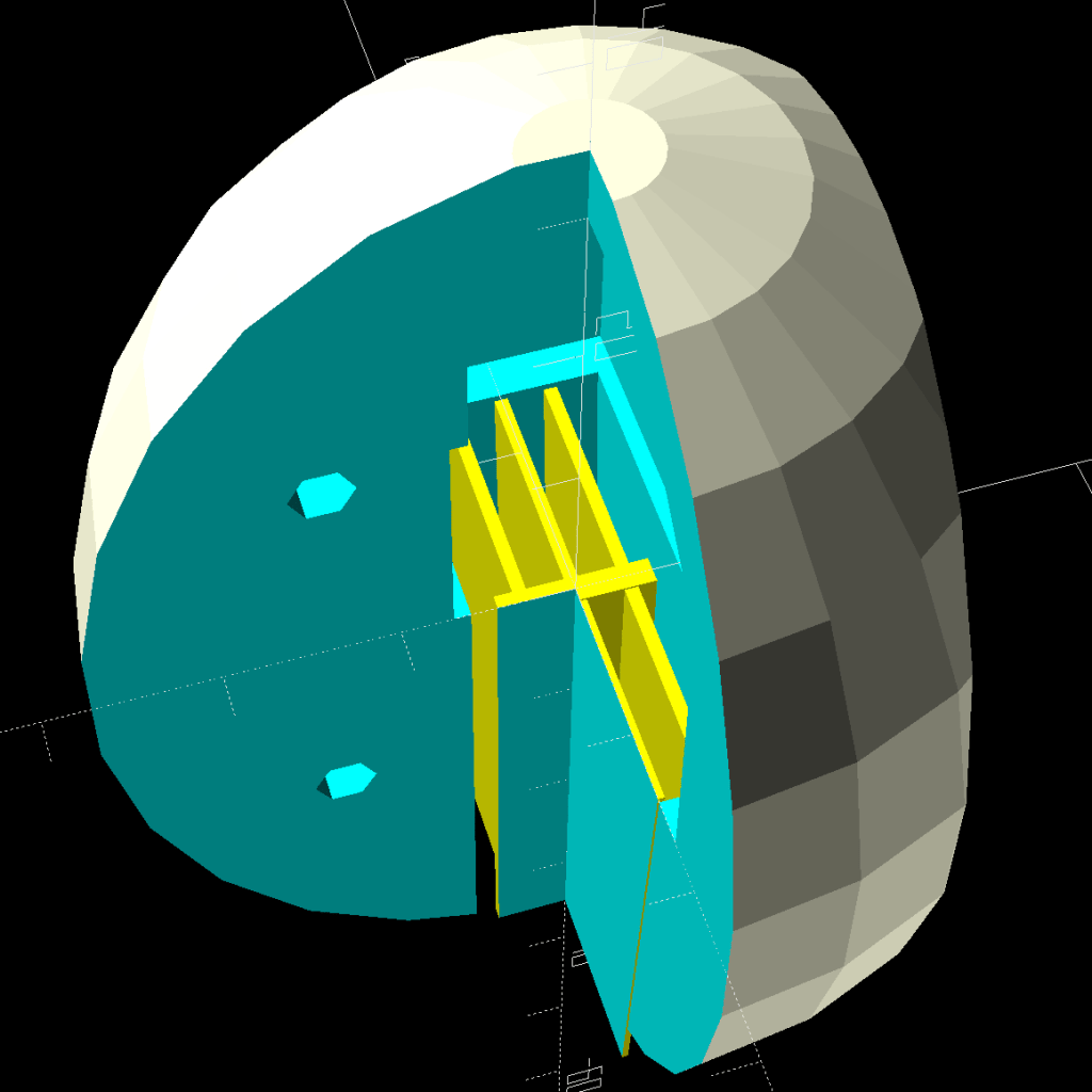
    Which, of course, meant conjuring a fixture from the vasty digital deep. The solid model includes the baseplate, two cutting templates, and a clamping fixture for engraving the cursor hairline:

    Cursor Fixture - build layout
    Cursor Fixture – build layout

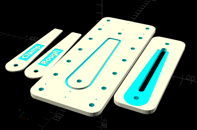
    The perimeter of the Clamp template on the far left is 0.5 mm inside the cursor perimeter. Needing only one Clamp, I could trace it on a piece of acrylic, bandsaw it pretty close, introduce it to Mr Belt Sander for final shaping, and finally drill the hole:

    Tek CC Cursor Fixture - clamp drilling
    Tek CC Cursor Fixture – clamp drilling

    The Rough template is 1.0 mm outside the cursor perimeter, so I can trace those outlines on a PET sheet:

    Tek CC Cursor Fixture - Rough template layout
    Tek CC Cursor Fixture – Rough template layout

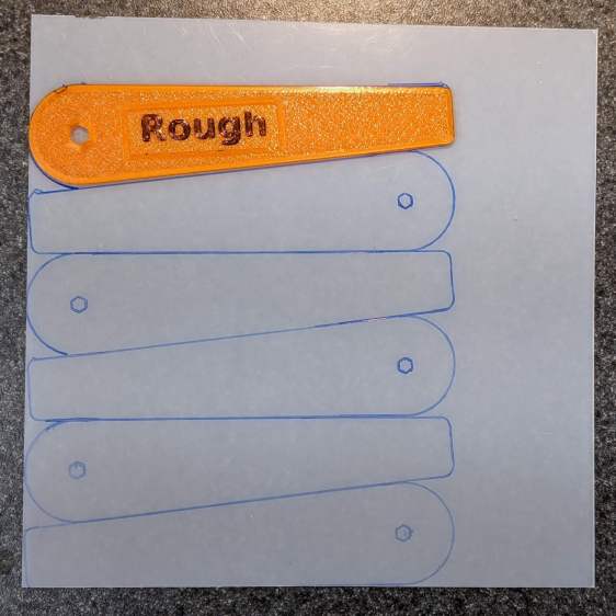
    Then cut the patterns with a scissors, stack ’em up, and tape the edges to keep them aligned:

    TekCC Cursor Fixture - Rough template
    TekCC Cursor Fixture – Rough template

    Align the stack by feel, apply the Clamp to hold them in place, and secure the stack with a Sherline clamp:

    Tek CC Cursor Fixture - outline rear clamp
    Tek CC Cursor Fixture – outline rear clamp

    The alert reader will note it’s no longer possible to machine the entire perimeter in one pass; more on that in a while.

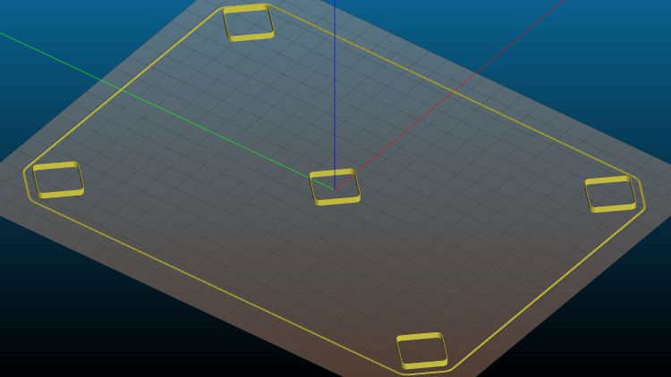
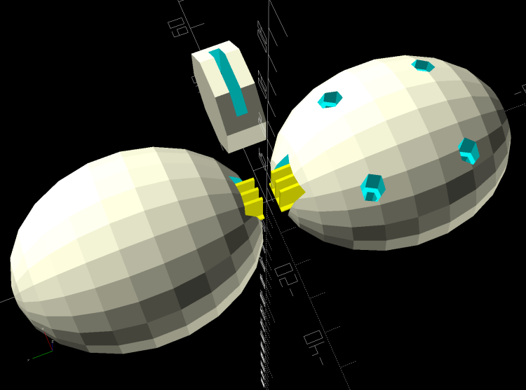
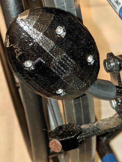
    The baseplate pretty much fills the entire Sherline tooling plate. It sports several alignment pips at known offsets from the origin at the center of the pivot hole:

    Tek CC Cursor Fixture - touch-off point
    Tek CC Cursor Fixture – touch-off point

    Dropping the laser alignment dot into a convenient pip, then touching off X and Y to the known offset sets the origin without measuring anything. Four screws in the corners align the plate well enough to not worry about angular tweakage.

    The OpenSCAD source code as a GitHub Gist:

    // Machining fixtures for Tek Circuit Computer cursor
    // Ed Nisley KE4ZNU Jan 2021
    Layout = "Show"; // [Show, Build, Cursor, Clamp, Rough, Engrave]
    /* [Hidden] */
    ThreadThick = 0.25;
    ThreadWidth = 0.40;
    HoleWindage = 0.2;
    Protrusion = 0.1; // make holes end cleanly
    inch = 25.4;
    function IntegerMultiple(Size,Unit) = Unit * ceil(Size / Unit);
    module PolyCyl(Dia,Height,ForceSides=0) { // based on nophead's polyholes
    Sides = (ForceSides != 0) ? ForceSides : (ceil(Dia) + 2);
    FixDia = Dia / cos(180/Sides);
    cylinder(d=(FixDia + HoleWindage),h=Height,$fn=Sides);
    }
    //———————-
    // Dimensions
    CursorHubOD = 1.0*inch; // original Tek CC was hard inch!
    CursorTipWidth = (9.0/16.0)*inch;
    CursorTipRadius = (1.0/16.0)*inch;
    CursorThick = 0.5; // plastic sheet thickness
    CutterOD = 3.175; // milling cutter dia
    CutterDepth = 2.0; // … depth of cut
    CutterLip = 0.5; // … clearance under edge
    ScribeOD = 3.0; // diamond scribe shank
    StudOC = [1.16*inch,1.16*inch]; // Sherline tooling plate grid
    StudClear = 5.0; // … screw clearance
    StudWasher = 11.0; // … washer OD
    CursorOffset = [-2*StudOC.x,0,0]; // hub center relative to fixture center
    // must have even multiples of stud spacing to put studs along centerlines
    BasePlateStuds = [6*StudOC.x,2*StudOC.y]; // fixture screws
    echo(str("Stud spacing: ",StudOC));
    CornerRad = 10.0; // corner radius
    BasePlate = [2*StudWasher + BasePlateStuds.x,2*StudWasher + BasePlateStuds.y,5.0];
    echo(str("Base Plate: ",BasePlate));
    EngravePlate = [5*StudOC.x,1.5*StudOC.y,BasePlate.z];
    echo(str("Engrave Plate: ",EngravePlate));
    TemplateThick = 6*ThreadThick;
    LegendThick = 2*ThreadThick;
    Gap = 3.0;
    //———————-
    // Import SVG of cursor outline
    // Requires our hub OD to match reality
    // Hub center at origin
    module CursorSVG(t=CursorThick,od=0) {
    hr = CursorHubOD/2;
    translate([-hr,-hr,0])
    linear_extrude(height=t,convexity=3)
    offset(r=od/2)
    import(file="/mnt/bulkdata/Project Files/Tektronix Circuit Computer/Firmware/TekCC-Cursor-Mark.svg",center=false);
    }
    //———————-
    // Milling fixture for cursor blanks
    module Fixture() {
    difference() {
    hull() // basic plate shape
    for (i=[-1,1], j=[-1,1])
    translate([i*(BasePlate.x/2 – CornerRad),j*(BasePlate.y/2 – CornerRad),0])
    cylinder(r=CornerRad,h=BasePlate.z,$fn=24);
    translate(CursorOffset + [0,0,BasePlate.z – CutterDepth])
    difference() {
    CursorSVG(CutterDepth + Protrusion,1.5*CutterOD);
    CursorSVG(CutterDepth + Protrusion,-CutterLip);
    }
    translate(CursorOffset + [0,0,BasePlate.z – 2*ThreadThick]) { // alignment pips
    for (x=[-20.0,130.0], y=[-30.0,0.0,30.0])
    translate([x,y,0])
    cylinder(d=4*ThreadWidth,h=1,$fn=6);
    for (x=[-30.0,130.0,150.0])
    translate([x,0,0])
    cylinder(d=4*ThreadWidth,h=1,$fn=6);
    }
    for (i=[-1,1], j=[-1,1]) // mounting stud holes
    translate([i*BasePlateStuds.x/2,j*BasePlateStuds.y/2,-Protrusion])
    rotate(180/6)
    PolyCyl(StudClear,BasePlate.z + 2*Protrusion,6);
    translate(CursorOffset + [0,0,-Protrusion]) // hub clamp hole
    rotate(180/6)
    PolyCyl(StudClear,BasePlate.z + 2*Protrusion,6);
    translate([2*StudOC.x,0,-Protrusion]) // tip clamp hole
    rotate(180/6)
    PolyCyl(StudClear,BasePlate.z + 2*Protrusion,6);
    for (i=[-2:2], j=[-1,1]) // side clamp holes
    translate([i*StudOC.x,j*StudOC.y,-Protrusion])
    rotate(180/6)
    PolyCyl(StudClear,BasePlate.z + 2*Protrusion,6);
    }
    }
    //———————-
    // Show-n-Tell cursor
    module Cursor() {
    difference() {
    CursorSVG(CursorThick,0.0);
    translate([0,0,-Protrusion])
    rotate(180/6)
    PolyCyl(StudClear,TemplateThick + 2*Protrusion,6);
    }
    }
    //———————-
    // Template for rough-cutting blanks
    module Rough() {
    bb = [40,12,LegendThick];
    difference() {
    CursorSVG(TemplateThick,1.0);
    translate([0,0,-Protrusion])
    rotate(180/6)
    PolyCyl(StudClear,TemplateThick + 2*Protrusion,6);
    difference() {
    translate([bb.x/2 + CursorHubOD/2,0,TemplateThick – bb.z/2 + Protrusion])
    cube(bb + [0,0,Protrusion],center=true);
    translate([bb.x/2 + CursorHubOD/2,0,TemplateThick – bb.z])
    linear_extrude(height=bb.z,convexity=10)
    text(text="Rough",size=7,spacing=1.00,font="DejaVu Sans:style:Bold",halign="center",valign="center");
    }
    }
    }
    //———————-
    // Template for aluminium clamping plate
    module Clamp() {
    bb = [40,12,LegendThick];
    difference() {
    CursorSVG(TemplateThick,-1.0);
    translate([0,0,-Protrusion])
    rotate(180/6)
    PolyCyl(StudClear,TemplateThick + 2*Protrusion,6);
    difference() {
    translate([bb.x/2 + CursorHubOD/2,0,TemplateThick – bb.z/2 + Protrusion])
    cube(bb + [0,0,Protrusion],center=true);
    translate([bb.x/2 + CursorHubOD/2,0,TemplateThick – bb.z])
    linear_extrude(height=bb.z,convexity=10)
    text(text="Clamp",size=7,spacing=1.00,font="DejaVu Sans:style:Bold",halign="center",valign="center");
    }
    }
    }
    //———————-
    // Engraving clamp
    module Engrave() {
    difference() {
    hull() // clamp outline
    for (i=[-1,1], j=[-1,1])
    translate([i*(EngravePlate.x/2 – CornerRad),j*(EngravePlate.y/2 – CornerRad),0])
    cylinder(r=CornerRad,h=EngravePlate.z,$fn=24);
    translate(CursorOffset + [0,0,-Protrusion])
    CursorSVG(CursorThick + Protrusion,0.5); // pocket for blank cursor
    translate(CursorOffset + [0,0,-Protrusion])
    rotate(180/6)
    PolyCyl(StudClear,EngravePlate.z + 2*Protrusion,6);
    translate([2*StudOC.x,0,-Protrusion])
    rotate(180/6)
    PolyCyl(StudClear,EngravePlate.z + 2*Protrusion,6);
    hull() {
    for (i=[-1,1])
    translate([i*1.5*StudOC.x,0,-Protrusion])
    PolyCyl(2*ScribeOD,EngravePlate.z + 2*Protrusion,8);
    }
    }
    }
    //———————-
    // Build it
    if (Layout == "Cursor") {
    Cursor();
    }
    if (Layout == "Clamp") {
    Clamp();
    }
    if (Layout == "Rough") {
    Rough();
    }
    if (Layout == "Engrave") {
    Engrave();
    }
    if (Layout == "Show") {
    Fixture();
    color("Green",0.3)
    translate(CursorOffset + [0,0,BasePlate.z + Protrusion])
    Cursor();
    color("Orange")
    translate(CursorOffset + [0,0,BasePlate.z + 10])
    Rough();
    color("Brown")
    translate(CursorOffset + [0,0,BasePlate.z + 20])
    Clamp();
    color("Gold")
    translate(0*CursorOffset + [0,0,BasePlate.z + 40])
    Engrave();
    }
    if (Layout == "Build"){
    rotate(90) {
    Fixture();
    translate([0,-((BasePlate.y + EngravePlate.y)/2 + Gap),EngravePlate.z])
    rotate([180,0,0])
    Engrave();
    translate(CursorOffset + [0,(BasePlate.y + CursorHubOD)/2 + Gap,0])
    Rough();
    translate(CursorOffset + [0,(BasePlate.y + 3*CursorHubOD)/2 + 2*Gap,0])
    Clamp();
    }
    }

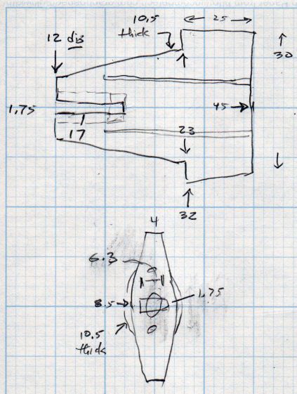
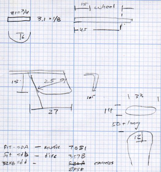
    The original doodle with some notions and dimensions that didn’t survive contact with reality:

    Cursor Fixture doodle
    Cursor Fixture doodle

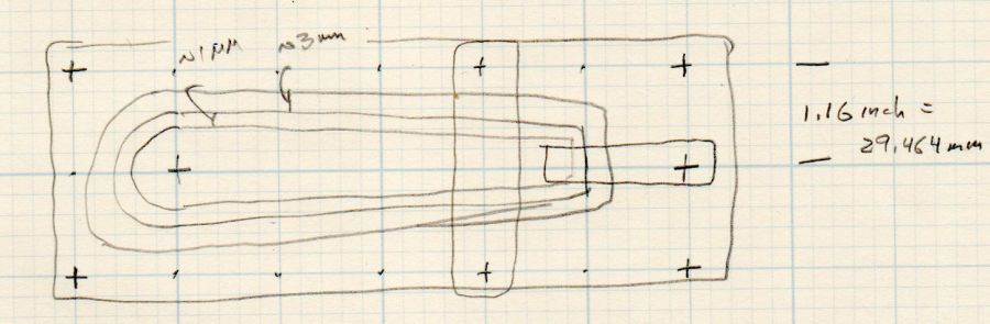
    I have no idea why the Sherline tooling plate has a 10-32 screw grid on 1.16 inch = 29.46 mm centers, but there they are.

  • Makergear M2: Initial PrusaSlicer Configuration

    Makergear M2: Initial PrusaSlicer Configuration

    After replacing the nozzle and the filament drive body on the M2, I figured I might as well throw all the balls in the air and switch to PrusaSlicer for all my slicing needs. It’s built from the Slic3r project, gaining features used by Prusa’s printers / filaments and a considerably improved UI, with a full-time paid staff working on it:

    PrusaSlicer screenshot
    PrusaSlicer screenshot

    Of course, I immediately turned on Expert mode.

    CAUTION: My heavily customized start_gcode will crash your M2, because you haven’t relocated the Z-axis switch, haven’t calibrated Z=0 at the platform surface, and don’t put the XY=0 origin in the center of the platform.

    You have been warned: consider this as a serving suggestion, not a finished product.

    Because everything I design looks more-or-less like a bracket, I absolutely don’t care about surface finish, and I’m content to use only a few colors of PETG from a single supplier, a single Slic3r configuration has sufficed for nearly everything I print. A few manual tweaks for specific models, perhaps to change the number of perimeters or the infill percentage, handle the remaining cases.

    With all that in mind, here’s the current result of File → Export → Export Config as a GitHub Gist:

    # generated by PrusaSlicer 2.2.0+linux-x64 on 2021-01-01 at 13:33:03 UTC
    avoid_crossing_perimeters = 0
    bed_custom_model =
    bed_custom_texture =
    bed_shape = -100x-125,100x-125,100×125,-100×125
    bed_temperature = 90
    before_layer_gcode =
    between_objects_gcode =
    bottom_fill_pattern = hilbertcurve
    bottom_solid_layers = 3
    bottom_solid_min_thickness = 0
    bridge_acceleration = 0
    bridge_angle = 0
    bridge_fan_speed = 100
    bridge_flow_ratio = 1
    bridge_speed = 50
    brim_width = 0
    clip_multipart_objects = 1
    colorprint_heights =
    complete_objects = 0
    cooling = 1
    cooling_tube_length = 5
    cooling_tube_retraction = 91.5
    default_acceleration = 0
    default_filament_profile = ""
    default_print_profile =
    deretract_speed = 0
    disable_fan_first_layers = 6
    dont_support_bridges = 1
    draft_shield = 0
    duplicate_distance = 6
    elefant_foot_compensation = 0
    end_filament_gcode = "; Filament-specific end gcode \n;END gcode for filament\n"
    end_gcode = ;– PrusaSlicer End G-Code for M2 starts –\n; Ed Nisley KE4NZU – 15 November 2013\nG1 Z160 F2000 ; lower bed\nG1 X135 Y100 F30000 ; nozzle to right, bed front\nM104 S0 ; drop extruder temperature\nM140 S0 ; drop bed temperature\nM106 S0 ; bed fan off\nM84 ; disable motors\n;– PrusaSlicer End G-Code ends –\n\n
    ensure_vertical_shell_thickness = 1
    external_perimeter_extrusion_width = 0
    external_perimeter_speed = 50%
    external_perimeters_first = 0
    extra_loading_move = -2
    extra_perimeters = 1
    extruder_clearance_height = 20
    extruder_clearance_radius = 20
    extruder_colour = ""
    extruder_offset = 0x0
    extrusion_axis = E
    extrusion_multiplier = 0.95
    extrusion_width = 0.4
    fan_always_on = 0
    fan_below_layer_time = 15
    filament_colour = #29B2B2
    filament_cooling_final_speed = 3.4
    filament_cooling_initial_speed = 2.2
    filament_cooling_moves = 4
    filament_cost = 25
    filament_density = 0.95
    filament_deretract_speed = nil
    filament_diameter = 1.72
    filament_load_time = 0
    filament_loading_speed = 28
    filament_loading_speed_start = 3
    filament_max_volumetric_speed = 0
    filament_minimal_purge_on_wipe_tower = 15
    filament_notes = ""
    filament_ramming_parameters = "120 100 6.6 6.8 7.2 7.6 7.9 8.2 8.7 9.4 9.9 10.0| 0.05 6.6 0.45 6.8 0.95 7.8 1.45 8.3 1.95 9.7 2.45 10 2.95 7.6 3.45 7.6 3.95 7.6 4.45 7.6 4.95 7.6"
    filament_retract_before_travel = nil
    filament_retract_before_wipe = nil
    filament_retract_layer_change = nil
    filament_retract_length = nil
    filament_retract_lift = nil
    filament_retract_lift_above = nil
    filament_retract_lift_below = nil
    filament_retract_restart_extra = nil
    filament_retract_speed = nil
    filament_settings_id = "M2 Esun PETG"
    filament_soluble = 0
    filament_toolchange_delay = 0
    filament_type = PET
    filament_unload_time = 0
    filament_unloading_speed = 90
    filament_unloading_speed_start = 100
    filament_vendor = (Unknown)
    filament_wipe = nil
    fill_angle = 45
    fill_density = 25%
    fill_pattern = 3dhoneycomb
    first_layer_acceleration = 0
    first_layer_bed_temperature = 90
    first_layer_extrusion_width = 0
    first_layer_height = 0.25
    first_layer_speed = 15
    first_layer_temperature = 250
    gap_fill_speed = 25
    gcode_comments = 0
    gcode_flavor = marlin
    gcode_label_objects = 0
    high_current_on_filament_swap = 0
    host_type = octoprint
    infill_acceleration = 0
    infill_every_layers = 1
    infill_extruder = 1
    infill_extrusion_width = 0
    infill_first = 1
    infill_only_where_needed = 0
    infill_overlap = 15%
    infill_speed = 60
    interface_shells = 0
    layer_gcode =
    layer_height = 0.25
    machine_max_acceleration_e = 10000,5000
    machine_max_acceleration_extruding = 10000,1250
    machine_max_acceleration_retracting = 10000,1250
    machine_max_acceleration_x = 2500,1000
    machine_max_acceleration_y = 2500,1000
    machine_max_acceleration_z = 2500,200
    machine_max_feedrate_e = 10000,5000
    machine_max_feedrate_x = 450,200
    machine_max_feedrate_y = 450,200
    machine_max_feedrate_z = 100,30
    machine_max_jerk_e = 100,50
    machine_max_jerk_x = 25,10
    machine_max_jerk_y = 25,10
    machine_max_jerk_z = 10,5
    machine_min_extruding_rate = 0,0
    machine_min_travel_rate = 0,0
    max_fan_speed = 100
    max_layer_height = 0
    max_print_height = 200
    max_print_speed = 80
    max_volumetric_speed = 0
    min_fan_speed = 100
    min_layer_height = 0.1
    min_print_speed = 10
    min_skirt_length = 25
    notes =
    nozzle_diameter = 0.35
    only_retract_when_crossing_perimeters = 1
    ooze_prevention = 0
    output_filename_format = [input_filename_base].gcode
    overhangs = 1
    parking_pos_retraction = 92
    perimeter_acceleration = 0
    perimeter_extruder = 1
    perimeter_extrusion_width = 0
    perimeter_speed = 50
    perimeters = 3
    post_process =
    print_host =
    print_settings_id = M2 Default
    printer_model =
    printer_notes =
    printer_settings_id = M2 Default
    printer_technology = FFF
    printer_variant =
    printer_vendor =
    printhost_apikey =
    printhost_cafile =
    raft_layers = 0
    remaining_times = 0
    resolution = 0.01
    retract_before_travel = 3
    retract_before_wipe = 0%
    retract_layer_change = 0
    retract_length = 1
    retract_length_toolchange = 10
    retract_lift = 0
    retract_lift_above = 0
    retract_lift_below = 0
    retract_restart_extra = 0
    retract_restart_extra_toolchange = 0
    retract_speed = 60
    seam_position = nearest
    serial_port =
    serial_speed = 250000
    silent_mode = 1
    single_extruder_multi_material = 0
    single_extruder_multi_material_priming = 1
    skirt_distance = 3
    skirt_height = 1
    skirts = 3
    slice_closing_radius = 0.049
    slowdown_below_layer_time = 5
    small_perimeter_speed = 25%
    solid_infill_below_area = 70
    solid_infill_every_layers = 0
    solid_infill_extruder = 1
    solid_infill_extrusion_width = 0
    solid_infill_speed = 75%
    spiral_vase = 0
    standby_temperature_delta = -5
    start_filament_gcode = "; Filament gcode\n"
    start_gcode = ;– PrusaSlicer Start G-Code for M2 starts –\n; Ed Nisley KE4NZU\n; Makergear V4 hot end\n; Origin at platform center, set by MANUAL_X_HOME_POS compiled constants\n; Z-min switch at platform, must move nozzle to X=135 to clear\nG90 ; absolute coordinates\nG21 ; millimeters\nM83 ; relative extrusion distance\nM104 S[first_layer_temperature] ; start extruder heating\nM140 S[first_layer_bed_temperature] ; start bed heating\nM17 ; enable steppers\nG4 P500 ; … wait for power up\nG92 Z0 ; set Z to zero, wherever it might be now\nG0 Z10 F1000 ; move platform downward to clear nozzle; may crash at bottom\nG28 Y ; home Y to clear plate, offset from compiled constant\nG28 X ; home X, offset from M206 X, offset from compiled constant\nG0 X135 Y0 F15000 ; move off platform to right side, center Y\nG28 Z ; home Z to platform switch, offset from M206 Z measured\nG0 Z2.0 F1000 ; get air under switch\nG0 Y-126 F10000 ; set up for priming, zig around corner\nG0 X0 ; center X\nG0 Y-124.5 ; just over platform edge\nG0 Z0 F500 ; exactly at platform\nM190 S[first_layer_bed_temperature] ; wait for bed to finish heating\nM109 S[first_layer_temperature] ; set extruder temperature and wait\nG1 E20 F300 ; prime to get pressure, generate blob on edge\nG0 Y-123 F5000 ; shear off blob\nG0 X15 F15000 ; jerk away from blob, move over surface\nG4 P500 ; pause to attach\nG1 X45 F500 ; slowly smear snot to clear nozzle\nG1 Z1.0 F2000 ; clear bed for travel\n;– PrusaSlicer Start G-Code ends –\n
    support_material = 0
    support_material_angle = 0
    support_material_auto = 1
    support_material_buildplate_only = 0
    support_material_contact_distance = 0.2
    support_material_enforce_layers = 0
    support_material_extruder = 1
    support_material_extrusion_width = 0.31
    support_material_interface_contact_loops = 0
    support_material_interface_extruder = 1
    support_material_interface_layers = 3
    support_material_interface_spacing = 0
    support_material_interface_speed = 100%
    support_material_pattern = rectilinear
    support_material_spacing = 2.5
    support_material_speed = 60
    support_material_synchronize_layers = 0
    support_material_threshold = 0
    support_material_with_sheath = 1
    support_material_xy_spacing = 50%
    temperature = 250
    thin_walls = 1
    threads = 4
    thumbnails =
    toolchange_gcode =
    top_fill_pattern = hilbertcurve
    top_infill_extrusion_width = 0
    top_solid_infill_speed = 50%
    top_solid_layers = 3
    top_solid_min_thickness = 0
    travel_speed = 300
    use_firmware_retraction = 0
    use_relative_e_distances = 0
    use_volumetric_e = 0
    variable_layer_height = 1
    wipe = 0
    wipe_into_infill = 0
    wipe_into_objects = 0
    wipe_tower = 0
    wipe_tower_bridging = 10
    wipe_tower_no_sparse_layers = 0
    wipe_tower_rotation_angle = 0
    wipe_tower_width = 60
    wipe_tower_x = 180
    wipe_tower_y = 140
    wiping_volumes_extruders = 70,70
    wiping_volumes_matrix = 0
    xy_size_compensation = 0
    z_offset = 0
  • MTD Snowthrower: Replacement Throttle Knob

    MTD Snowthrower: Replacement Throttle Knob

    The throttle knob on our MTD snowthrower (a.k.a. snowblower) cracked apart around its metal shaft when I pulled it upward. A temporary fix involving duct tape and cable ties sufficed to start the engine, although the usual intense vibration shook the knob loose somewhere along the driveway during the next hour.

    Update: Found it!

    Although I have no photographic evidence, I did make a few quick measurements:

    Throttle Knob Dimension Doodles
    Throttle Knob Dimension Doodles

    It fits an MTD model E6A4E, but I suspect nearly all their engines have identical throttle shafts:

    Snowthrower Throttle Knob - stem end - solid model
    Snowthrower Throttle Knob – stem end – solid model

    The only practical way to build the thing has it standing on the shaft end, surrounded by a brim to improve adhesion, so I added (actually, subtracted) a pair of holes for music-wire reinforcements:

    Snowthrower throttle knob - reinforcing wires
    Snowthrower throttle knob – reinforcing wires

    It definitely has a stylin’ look, next to the original choke control knob:

    Snowthrower throttle knob - installed
    Snowthrower throttle knob – installed

    I omitted the finger grip grooves for obvious reasons.

    The slot-and-hole came out slightly smaller than the metal shaft and, rather than wait for epoxy to cure, I deployed a 230 W soldering gun (not a piddly temperature-controlled iron suitable for electronics) on the shaft and melted it into the knob.

    More snow may arrive this week and I printed another knob just in case …

    The OpenSCAD source code as a GitHub Gist:

    // MTD Snowthrower Throttle Knob
    // Ed Nisley KE4ZNU 2020-12-18
    /* [Options] */
    Layout = "Show"; // [Build, Show]
    // Extrusion parameters
    /* [Hidden] */
    ThreadThick = 0.25;
    ThreadWidth = 0.40;
    HoleWindage = 0.2;
    Protrusion = 0.1; // make holes end cleanly
    inch = 25.4;
    function IntegerMultiple(Size,Unit) = Unit * ceil(Size / Unit);
    //———————-
    // Dimensions
    Throttle = [17.0,1.85,6.5]; // blade insertion, thickness, width
    PaddleSize = [25,30,9];
    PaddleRound = 4.0;
    PaddleThick = 8.5;
    StemDia = 13.0;
    StemLength = 20.0;
    PinDia = 1.6;
    PinLength = PaddleSize.x + StemLength/2;
    echo(str("Pin: ",PinLength," x ",PinDia," mm"));
    //———————-
    // Useful routines
    module PolyCyl(Dia,Height,ForceSides=0) { // based on nophead's polyholes
    Sides = (ForceSides != 0) ? ForceSides : (ceil(Dia) + 2);
    FixDia = Dia / cos(180/Sides);
    cylinder(r=(FixDia + HoleWindage)/2,
    h=Height,
    $fn=Sides);
    }
    //———————-
    // Pieces
    module Paddle() {
    difference() {
    hull() {
    translate([PaddleSize.x/2,0,0]) {
    for (i=[-1,1], j=[-1,1])
    translate([i*(PaddleSize.x – PaddleRound)/2,j*(PaddleSize.y – PaddleRound)/2,0])
    sphere(d=PaddleRound,$fn=12);
    rotate([0,90,0]) rotate(180/12)
    cylinder(d=PaddleThick,h=PaddleSize.x,,center=true,$fn=12);
    }
    translate([-StemLength,0,0])
    rotate([0,90,0]) rotate(180/12)
    cylinder(d=StemDia,h=Throttle.x,center=false,$fn=12);
    }
    translate([-StemLength,0,0])
    cube([2*Throttle.x,Throttle.y,Throttle.z],center=true);
    translate([-(StemLength + Protrusion),0,0])
    rotate([0,90,0]) rotate(0*180/6)
    PolyCyl(2*Throttle.y,Throttle.x,6);
    for (j=[-1,1])
    translate([-StemLength/2,j*PaddleSize.y/6,0])
    rotate([0,90,0]) rotate(180/4)
    PolyCyl(PinDia,PinLength,4);
    }
    }
    //———————-
    // Build it
    if (Layout == "Show")
    Paddle();
    if (Layout == "Build") {
    translate([0,0,StemLength])
    rotate([0,-90,0])
    Paddle();
    }
  • Makergear M2: Platform Z=0 and Alignment Check

    Makergear M2: Platform Z=0 and Alignment Check

    After replacing the nozzle and filament drive on the M2, it’s definitely time to verify that the Z=0 point remains at the platform surface and the whole affair is properly aligned.

    Distribute five thinwall open squares across the platform:

    Calibration Boxes - platform alignment - 2020-12-11
    Calibration Boxes – platform alignment – 2020-12-11

    Because they’re well separated and only 3 mm tall, I set Slic3r to print them sequentially to eliminate a whole bunch of back-and-forth travel for each layer.

    Print and measure the results:

    Calibration Boxes - initial M206 Z-2.50 - 2020-12-11
    Calibration Boxes – initial M206 Z-2.50 – 2020-12-11

    The outer numbers come from the skirt around the whole platform in units of 0.01 mm: 22 → 0.22 mm. The five inner numbers are the eyeballometric average of four measurements across each square.

    They came short enough that adding 0.25 mm to their height would improve the outcome. The scribbles in the upper right corner show the initial Z offset was -2.50 mm, which means -2.75 mm should do the trick; remember to save the new value in EEPROM with M500.

    Print the same G-Code file with the new offset and measure:

    Calibration Boxes - M206 Z-2.75 - 2020-12-11
    Calibration Boxes – M206 Z-2.75 – 2020-12-11

    Can’t get much closer than that!

    The skirt gains only 0.1 mm for reasons unknown to me. It’s a good diagnostic tool for keeping an eye on the overall alignment without having to run more calibration squares, though.

    Comparing the center squares (bottom layers facing each other in the middle) from the two sets shows the difference:

    Test Squares 2.73 3.01 mm - 2020-12-11
    Test Squares 2.73 3.01 mm – 2020-12-11

    The bottom three layers got pretty well squashed with the previous offset. It’s missing about a full layer, although the nozzle wasn’t mashed flat / blocked against the platform. All the layers in the post-adjustment square look identical, as they should.

    The wall thickness on the latter squares runs from 0.40 to 0.44 mm, with an eyeballometric average around 0.43, so tweaking the Extrusion Multiplier down by maybe 5% would be in order if I were being fussy.

    Overall, not bad for a new setup!

  • Makergear M2: New Filament Drive and Guide Tube Adapter

    Makergear M2: New Filament Drive and Guide Tube Adapter

    After replacing the M2’s nozzle, I also installed a spare filament drive:

    Makergear M2 filament drive R3 - installed
    Makergear M2 filament drive R3 – installed

    That’s the V4 R3 version, although I bought it from Makergear rather than fight with all the support required to get a proper bearing opening.

    The long M4 screw and spring apply a constant force to the filament against the drive gear, rather than the constant position from the default (and much shorter) stock screw. The lever arm does have some springiness, but not much travel, so IMO the spring works better with the fine teeth in the drive gear.

    This drive has a 5 mm hole at the top for the stock PTFE guide tube, which I long ago replaced with ¼ inch OD HDPE tubing to reduce the friction required to get the filament off the spool and into the hot end. The rather hideous hot-melt glue blob holding a ¼ inch ID tube onto the previous drive never failed enough to bother me, but a little lathe action produced a much better adapter:

    Makergear M2 filament drive R3 - guide adapter
    Makergear M2 filament drive R3 – guide adapter

    It’s a chunk of ⅜ inch = 9.5 mm Delrin rod with a 2.4 mm hole through that 5 mm spigot for easy extraction of a gear-mashed 1.75 mm filament. The other end has a 6.5 mm hole drilled 20 mm deep to hold the guide tube.

    Looks downright dressy, it does!

  • Makergear M2: New Nozzle

    Makergear M2: New Nozzle

    A second clog in the M2’s hot end prompted me to dismantle the hot end:

    Makergear M2 V4 hot end - eroded silicone coat
    Makergear M2 V4 hot end – eroded silicone coat

    That’s what half a year of use does to a nice, shiny coat of high-temperature silicone rubber.

    This being the first time I’ve dismantled the hot end, here’s what lies inside:

    Makergear M2 V4 hot end - tapered inner guide
    Makergear M2 V4 hot end – tapered inner guide

    The tighter you make the nozzle, the closer the fit inside the hot end, and the more heat gets transferred to the plastic. The bright ring just to the right of the plastic drool shows where it fits into the brass nozzle.

    Peeling the remaining silicone off the nozzle, scraping off the black PETG around the tip, and scraping the gunk out left the inside a bit scuffed:

    Makergear 0.35 mm nozzle - interior
    Makergear 0.35 mm nozzle – interior

    The orifice still looks good and is still as close to 0.35 mm as I can measure eyeballometrically:

    Makergear 0.35 mm nozzle - exterior
    Makergear 0.35 mm nozzle – exterior

    Despite what it looks like, that’s actually a very thin PETG layer.

    Having a spare nozzle on the shelf, I decided to install it and leave the old nozzle as a backup. I’ve probably wrecked the snug seal required to keep the plastic out of the hot end.

    A fresh coat of silicone, reset the position with the platform at Z=0, and it’s back in action:

    Makergear M2 V4 hot end - Z zero set
    Makergear M2 V4 hot end – Z zero set

    The PETG remnants show I didn’t get the nozzle quite tight enough on the first attempt, but it’s all good now. The rubbery fiberglass insulator will conceal the mess.

    Protip: Always remove the hot end from the printer and clamp it securely before unscrewing the nozzle, because the very thin heat break (over on the right in the second picture) will snap under less torque than you need to break the nozzle free.

    You should unscrew the nozzle with the hot end warm enough to soften whatever plastic you’re using, lest it have glued everything inside into a solid lump.

  • Drive Wheelchair Brake Knob

    Drive Wheelchair Brake Knob

    The bent-steel brake levers on our Drive Blue Streak wheelchair present themselves edge-on to the rider:

    Drive Wheelchair Brake
    Drive Wheelchair Brake

    There are good mechanical reasons for shaping and orienting the steel like that, but the handle concentrates the considerable force required to push the brake tab into the rubberoid tire on your (well, my) palms. After a couple of weeks, I decided I didn’t need two more sore spots and conjured a palm-filling knob from the vasty digital deep:

    Wheelchair Brake Knob - installed
    Wheelchair Brake Knob – installed

    Bonus part: the little octagon near the wheel prevents the leg rest (seen in the first picture) from smashing into the end of the brake tab and chipping the lovely blue powder coat. The brown fuzzy felt foot seemed like a good idea at the time, but isn’t strictly necessary.

    A cylindrical handle on Thingiverse apparently fits on the bare steel underneath the rubberish “cushion”, but cutting a perfectly good, albeit uncomfortable, cushion off seemed like a step in the wrong direction. My knob thus descends from a doodle of the OEM dimensions:

    Drive Wheelchair Brake Handle - dimensions
    Drive Wheelchair Brake Handle – dimensions

    The knob builds in two halves adjoining the bonus octagon, which stands on edge to eliminate support inside its slot:

    Wheelchair Brake Mods - solid model - build layout
    Wheelchair Brake Mods – solid model – build layout

    You (probably) need two of all those shapes, a job your slicer is ready to perform. At three hours for each knob, I just printed the same G-Code twice.

    You can customize the knob width to fit your palm, with the other two dimensions fitting themselves around the cushion. Mary and I settled on a knob size that fits both our hands reasonably well, so it’s probably not critical.

    I tried building the knob halves without support for the first prototype, but the sloped upper surface produced awful bridging:

    Wheelchair Brake Knob - unsupported interior
    Wheelchair Brake Knob – unsupported interior

    It’s easy enough to design a customized support structure:

    Wheelchair Brake Mods - cross section
    Wheelchair Brake Mods – cross section

    I oriented the knob to put the split on the narrow sides of the brake handle in order to not have a seam facing my palm:

    Wheelchair Brake Knob - rear half installed
    Wheelchair Brake Knob – rear half installed

    The quartet of M3×20 mm socket-head cap screws thread into brass inserts epoxied into the rear half. I recessed their heads deeply into the front half and avoided thinking too hard about plugs matching the surface curvature:

    Wheelchair Brake Knob - front view
    Wheelchair Brake Knob – front view

    The low-vertex-count polygonal shape is a stylin’ thing and produces a nice feel during a firm shove, at least to my paws. Although I’d rather not need a wheelchair at all, setting the brakes now seems authoritative instead of annoying.

    The OpenSCAD source code as a GitHub gist:

    // Pride wheelchair brake lever mods
    // Ed Nisley KE4ZNU 2020-11
    /* [Layout options] */
    Layout = "Build"; // [Build, Show, Fit, TabCap, Handle, Knob, Support]
    // Hold up the knob's inside
    Support = true;
    /* [Extrusion parameters] */
    /* [Hidden] */
    ThreadThick = 0.25;
    ThreadWidth = 0.40;
    HoleWindage = 0.2;
    function IntegerMultiple(Size,Unit) = Unit * ceil(Size / Unit);
    function IntegerLessMultiple(Size,Unit) = Unit * floor(Size / Unit);
    Protrusion = 0.1; // make holes end cleanly
    inch = 25.4;
    ID = 0;
    OD = 1;
    LENGTH = 2;
    //———————-
    // Useful routines
    module PolyCyl(Dia,Height,ForceSides=0) { // based on nophead's polyholes
    Sides = (ForceSides != 0) ? ForceSides : (ceil(Dia) + 2);
    FixDia = Dia / cos(180/Sides);
    cylinder(r=(FixDia + HoleWindage)/2,h=Height,$fn=Sides);
    }
    //* [Basic dimensions] */
    WallThick = 4.0; // min wall thickness
    Screw = [3.0,5.5,20.0]; // thread, head, length under head
    Insert = [3.0,4.1,8.0]; // thread, knurl, length
    //———————-
    // Brake tab cap
    BrakeTab = [15,21,3.1]; // length to wheel, width, thickness
    BrakeTabSagitta = 8.0; // height of curved endcap
    CapOAL = [BrakeTab.y + 2*WallThick,BrakeTab.y + 2*WallThick,BrakeTab.z + 2*WallThick];
    module TabCap() {
    difference() {
    rotate(180/8)
    cylinder(d=CapOAL.y,h=CapOAL.z,center=true,$fn=8);
    translate([BrakeTab.x/2,0,0])
    cube(BrakeTab,center=true);
    rotate(180/8)
    cylinder(d=BrakeTab.y/cos(180/8),h=BrakeTab.z,center=true,$fn=8);
    }
    }
    //———————-
    // Brake lever handle
    // Soft covering with rounded sides that we square off for simplicity
    HandleRibs = [15,34,14]; // ignoring slight taper from end
    HandleCore = [50.0,24.0,12.0]; // straight section of lever to top of ribs
    HandleTipWidth = 30.0; // ignoring actual sector height
    module Handle() {
    union() {
    hull() {
    rotate(180/8)
    cylinder(d=HandleTipWidth/cos(180/8),h=HandleCore.z,center=true,$fn=8);
    translate([-HandleCore.x/2,0,0])
    cube(HandleCore,center=true);
    }
    translate([-(3*HandleCore.x/2 – Protrusion),0,0]) // extend base for ball trimming
    cube(HandleCore,center=true);
    translate([-HandleRibs.x/2,0,0])
    cube(HandleRibs,center=true);
    }
    }
    //———————-
    // Support structure for handle cavity inside knob
    // Totally ad-hoc tweakage
    // Remember it's lying on its side to match the handle
    NumRibs = 2 + 1; // must be odd
    RibSpace = floor(HandleCore.z/(NumRibs + 1));
    module KnobSupport() {
    color("Yellow") { // support overlaps in the middle
    render(convexity=3)
    intersection() {
    for (k=[-1,1])
    translate([0,k*ThreadThick,0]) // shrink inward to break adhesion
    Handle();
    translate([(HandleCore.x – HandleRibs.x)/2 – HandleCore.x – Protrusion,0,0])
    cube([HandleCore.x – HandleRibs.x,HandleRibs.y,HandleCore.z],center=true);
    union()
    for (k=[-floor(NumRibs/2):floor(NumRibs/2)])
    translate([0,0,k* RibSpace])
    cube([2*HandleCore.x,HandleRibs.y,2*ThreadWidth],center=true);
    }
    translate([(HandleCore.x – HandleRibs.x)/2 – HandleCore.x,0,0])
    cube([HandleCore.x – HandleRibs.x,4*ThreadWidth,NumRibs*RibSpace],center=true);
    }
    }
    //———————-
    // Brake handle knob
    // Largely built with magic numbers
    // Includes support because it's not really optional
    KnobOD = 55.0;
    KnobOffset = HandleRibs.x/1;
    KnobSides = 2*4*3;
    module Knob() {
    difference() {
    hull() {
    resize([0,HandleRibs.y + 4*WallThick,HandleCore.x + HandleTipWidth/2 + WallThick])
    sphere(d=KnobOD,$fn=KnobSides);
    }
    translate([0,0,KnobOffset])
    rotate([0,-90,0])
    Handle();
    for (i=[-1,1],k=[-1,1])
    translate([i*KnobOD/4,0,k*KnobOD/4]) {
    rotate([90,0,0])
    PolyCyl(Insert[OD],1.5*Insert[LENGTH],6);
    translate([0,-Screw[LENGTH]/2,0])
    rotate([-90,0,0])
    PolyCyl(Screw[ID],KnobOD,6);
    translate([0,Screw[LENGTH] – Insert[LENGTH],0])
    rotate([-90,0,0])
    PolyCyl(Screw[OD],KnobOD,6);
    }
    }
    if (Support)
    translate([0,0,KnobOffset])
    rotate([0,-90,0])
    KnobSupport();
    }
    //———————-
    // Lash it together
    if (Layout == "TabCap") {
    TabCap();
    }
    if (Layout == "Handle") {
    Handle();
    }
    if (Layout == "Support") {
    KnobSupport();
    }
    if (Layout == "Knob") {
    Knob();
    }
    if (Layout == "Show") {
    translate([60,0,0])
    TabCap();
    Knob();
    }
    if (Layout == "Fit") {
    translate([60,0,0])
    difference() {
    TabCap();
    translate([0,0,CapOAL.z/2])
    cube(CapOAL,center=true);
    }
    difference() {
    Knob();
    translate([KnobOD + KnobOD/4,0*KnobOD,0])
    cube(2*KnobOD,center=true);
    translate([-KnobOD,-KnobOD,0])
    cube(2*KnobOD,center=true);
    }
    }
    if (Layout == "Build") {
    translate([KnobOD/2,0,(CapOAL.y*cos(180/8))/2])
    rotate([0,-90,90])
    TabCap();
    for (j=[-1,1])
    translate([0,-j*0.75*HandleCore.x,0])
    difference() {
    rotate([j*90,0,0])
    Knob();
    translate([0,0,-KnobOD])
    cube(2*KnobOD,center=true);
    }
    }

    A doodle with dimensions of other parts:

    Drive Wheelchair - brake footrest tab dimensions
    Drive Wheelchair – brake footrest tab dimensions

    The angled tab on the middle left is for the leg rest release latch, but I decided not to silk-purse-ize the thing.