The Smell of Molten Projects in the Morning

Ed Nisley's Blog: Shop notes, electronics, firmware, machinery, 3D printing, laser cuttery, and curiosities. Contents: 100% human thinking, 0% AI slop.

Tag: M2

Using and tweaking a Makergear M2 3D printer

  • Bike Helmet Mirror: Ball Mount

    Bike Helmet Mirror: Ball Mount

    Nine years ago, I didn’t know how enough to design a bike helmet mirror with a ball mount, but even an old dog can learn a new trick:

    Helmet Mirror Ball Mount - on helmet
    Helmet Mirror Ball Mount – on helmet

    However, it’s worth noting my original, butt-ugly Az-El mounts lasted for all of those nine years, admittedly with adjustments along the way, which is far more than the commercial mounts making me unhappy enough to scratch my itch.

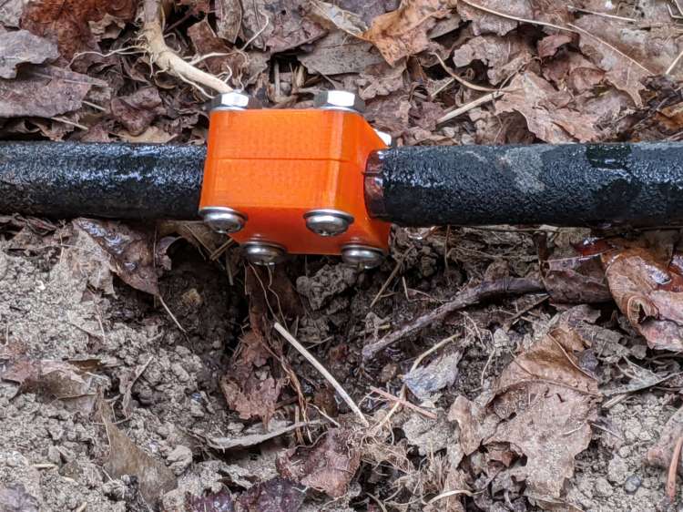
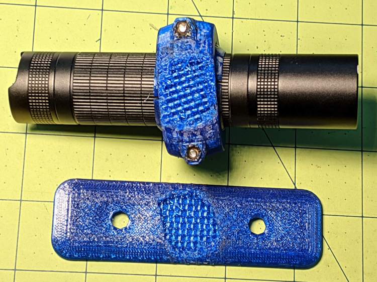
    The mount adapts the split spherical clamp from the daytime running light:

    Helmet Mirror Mount - Ball
    Helmet Mirror Mount – Ball

    Scaling it down for a 10 mm polypropylene ball around the base of the 30 mm inspection mirror’s shaft simplified everything:

    Helmet Mirror Ball Mount - drilled ball test
    Helmet Mirror Ball Mount – drilled ball test

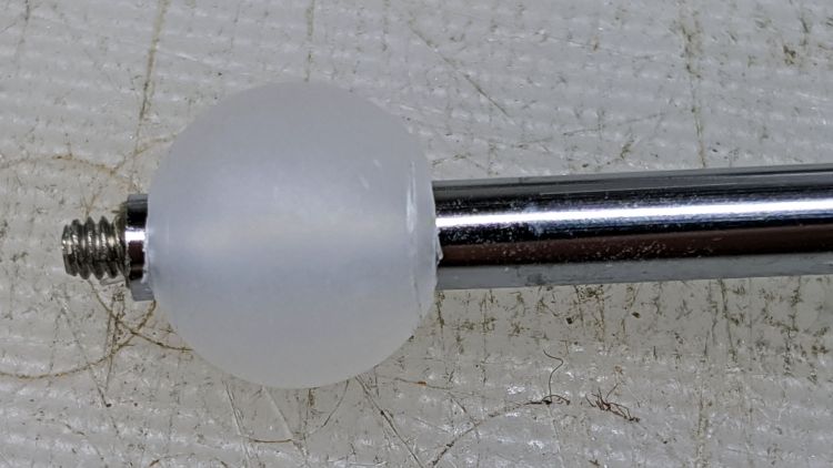
    I’m reasonably sure I couldn’t have bought 100 polypro balls for eight bucks a decade ago, but we’ll never know. Drilling the hole was a complete botch job, about which more later. The shaft came from a spare mirror mount I made up a while ago; a new shaft appears below.

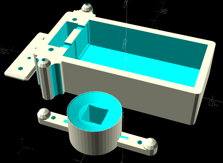
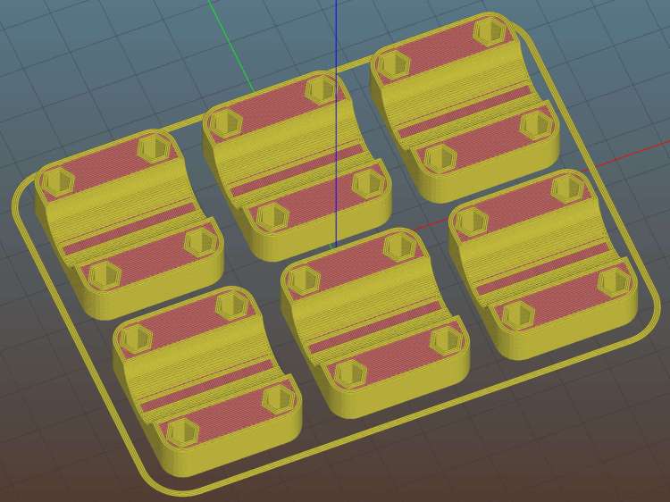
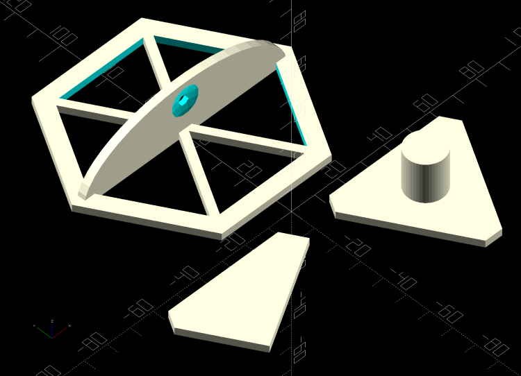
    The solid model, like Gaul, is in three parts divided:

    Helmet Mirror Ball Mount - Slic3r
    Helmet Mirror Ball Mount – Slic3r

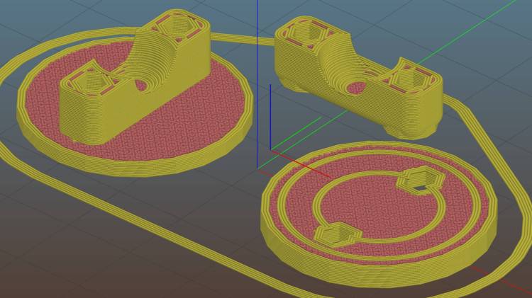
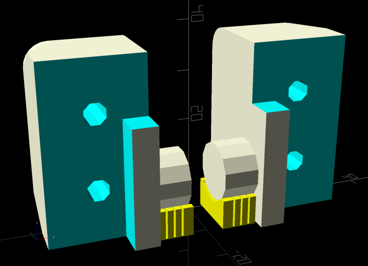
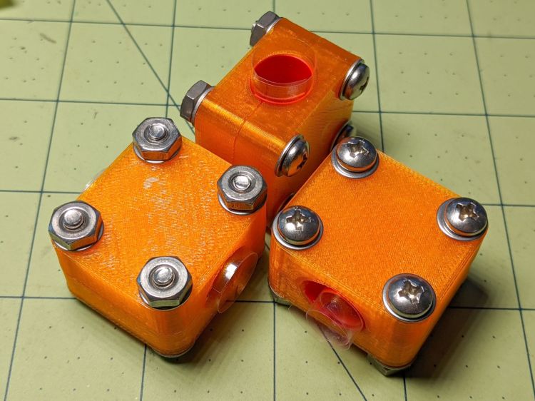
    The helmet plate (on the right) has a slight indent more-or-less matching the helmet curvature and gets a layer of good double-stick foam tape. The clamp base (on the left) has a pair of brass inserts epoxied into matching recesses below the M3 clearance holes:

    Helmet Mirror Ball Mount - inserts
    Helmet Mirror Ball Mount – inserts

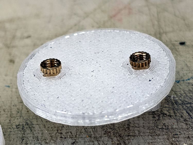
    A layer of epoxy then sticks the helmet plate in place, with the inserts providing positive alignment:

    Helmet Mirror Ball Mount - plates
    Helmet Mirror Ball Mount – plates

    The clamp screws pull the inserts against the plastic in the clamp base, so they can’t pull out or through, and the plates give the epoxy enough bonding surface that (I’m pretty sure) they won’t ever come apart.

    I turned down a 2 mm brass insert to fit inside the butt end of the mirror shaft and topped it off with a random screw harvested from a dead hard drive:

    Helmet Mirror Ball Mount - assembled - rear view
    Helmet Mirror Ball Mount – assembled – rear view

    At the start, it wasn’t obvious the shaft would stay stuck in the ball, so I figured making it impossible to pull out would eliminate the need to find it by the side of the road. As things turned out, the clamp exerts enough force to ensure the shaft ain’t goin’ nowhere, so I’ll plug future shafts with epoxy.

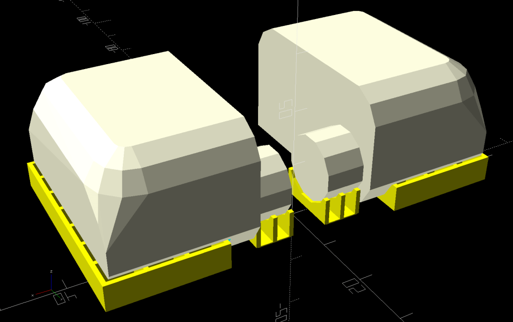
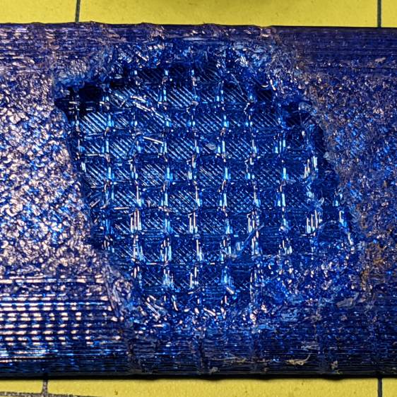
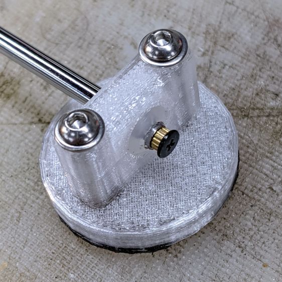
    The front side of the clamp looks downright sleek:

    Helmet Mirror Ball Mount - assembled - front view
    Helmet Mirror Ball Mount – assembled – front view

    Well, how about “chunky”?

    The weird gray-black highlights are optical effects from clear / natural PETG, rather than embedded grunge; it looks better in person. I should have used retina-burn orange or stylin’ black.

    This mount is much smaller than the old one and should, in the event of a crash, not cause much injury. Based on how the running light clamp fractures, I expect the clamp will simply tear out of the base on impact. In the last decade, neither of us has crashed, so I don’t know what the old mount would do.

    The clamp is 7 mm thick (front-to-back), set by the M3 washer diameter, with 1.5 mm of ball sticking out on each side. The model has a kerf one thread high (0.25 mm) between the pieces to add clamping force and, with the screws tightened down, moving the ball requires a disturbingly large effort. I added a touch of rosin and that ball straight-up won’t move, which probably means the shaft will bend upon droppage; I have several spare mirrors in stock.

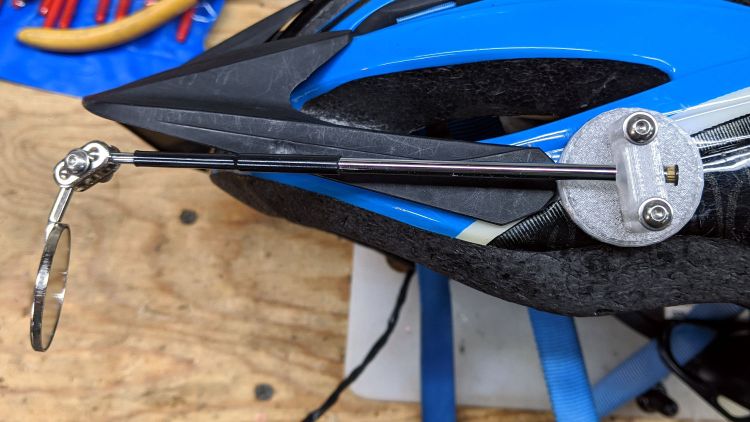
    On the other paw, the ball turns smoothly in the clamp and it’s easy to position the shaft as needed: much better than the old Az-El mount!

    The inspection mirror hangs from a double ball joint which arrives with a crappy screw + nut. I epoxied the old mirror mount nut in place, but this time around I drilled the plates for a 3 mm stainless SHCS, used a wave washer for a bit of flexible force, and topped it off with a nyloc nut:

    Helmet Mirror Ball Mount - mirror joint
    Helmet Mirror Ball Mount – mirror joint

    I’m unhappy with how it looks and don’t like how the washer hangs in free space between those bumps, so I may eventually turn little brass fittings to even things out. It’s either that or more epoxy.

    So far, though, it’s working pretty well and both units meet customer requirements.

    The OpenSCAD source code as a GitHub Gist:

    // Bike helmet mirror mount – ball joint
    // Ed Nisley KE4ZNU 2020-09
    /* [Layout options] */
    Layout = "Build"; // [Build, Show, Plate, Base, Clamp]
    //– Extrusion parameters
    // Extrusion parameters
    /* [Hidden] */
    ThreadThick = 0.25;
    ThreadWidth = 0.40;
    HoleWindage = 0.2;
    function IntegerMultiple(Size,Unit) = Unit * ceil(Size / Unit);
    function IntegerLessMultiple(Size,Unit) = Unit * floor(Size / Unit);
    Protrusion = 0.1; // make holes end cleanly
    inch = 25.4;
    ID = 0;
    OD = 1;
    LENGTH = 2;
    //- Basic dimensions
    MountDia = 30.0; // footprint on helmet
    BallDia = 10.0;
    BallRad = BallDia / 2;
    WallThick = IntegerMultiple(2.0,ThreadWidth);
    FloorThick = IntegerMultiple(2.0,ThreadThick);
    CornerRound = 2.0;
    Insert = [3.0,4.0,4.0]; // threaded brass insert
    Screw = [3.0,5.5,25.0]; // clamp screw
    Washer = [3.7,7.0,0.7]; // washer
    ShowGap = 2.0;
    BuildGap = 5.0;
    //– Helmet Interface Plate
    ScrewOC = BallDia + 2*WallThick + Screw[ID];
    echo(str("Screw OC: ",ScrewOC));
    Clamp = [ceil(Washer[OD]), // barely holds washer under screw
    ScrewOC + Washer[OD], // minimal clearance for washer
    BallDia +2*FloorThick // screw fits through insert
    ];
    Kerf = ThreadThick;
    echo(str("Clamp: ",Clamp));
    HelmetCX = 60.0; // empirical helmet side curve
    HelmetMX = 3.0;
    HelmetRX = (pow(HelmetMX,2) + pow(HelmetCX,2)/4)/(2*HelmetMX);
    HelmetPlateC = MountDia;
    HelmetPlateTheta = atan(HelmetPlateC/HelmetRX);
    HelmetPlateM = 2*HelmetRX*pow(sin(HelmetPlateTheta/4),2);
    echo(str("Plate indent: ",HelmetPlateM));
    HelmetPlateThick = max(FloorThick,0.6*Insert[LENGTH]) + HelmetPlateM;
    echo(str("Screw length: ",Clamp.z + Insert[LENGTH]));
    MountSides = 2*3*4;
    //———————-
    // Useful routines
    module PolyCyl(Dia,Height,ForceSides=0) { // based on nophead's polyholes
    Sides = (ForceSides != 0) ? ForceSides : (ceil(Dia) + 2);
    FixDia = Dia / cos(180/Sides);
    cylinder(r=(FixDia + HoleWindage)/2,h=Height,$fn=Sides);
    }
    //———————-
    // Clamp frame around ball
    module ClampFrame() {
    difference() {
    union() {
    hull()
    for (i=[-1,1], j=[-1,1]) {
    translate([i*(Clamp.x/2 – CornerRound),j*(Clamp.y/2 – CornerRound),Clamp.z/2 – CornerRound])
    sphere(r=CornerRound,$fn=24);
    translate([i*(Clamp.x/2 – CornerRound),j*(Clamp.y/2 – CornerRound),-Clamp.z/2])
    cylinder(r=CornerRound,$fn=24);
    }
    for (j=[-1,1])
    translate([0,j*ScrewOC/2,0])
    rotate(180/12)
    cylinder(d=Washer[OD],h=Clamp.z/2,$fn=12);
    }
    sphere(d=BallDia + HoleWindage,$fn=48);
    cube([2*MountDia,2*MountDia,Kerf],center=true);
    for (j=[-1,1])
    translate([0,j*ScrewOC/2,-Screw[LENGTH]])
    rotate(180/6)
    PolyCyl(Screw[ID],2*Screw[LENGTH],6);
    }
    }
    module ClampSelect(Section) {
    XlateZ = (Section == "Top") ? Clamp.z/2 :
    (Section == "Bottom") ? -Clamp.z/2 :
    0;
    intersection(convexity=5) {
    ClampFrame();
    translate([0,0,XlateZ])
    cube([2*Clamp.x,2*Clamp.y,Clamp.z + 2*Protrusion],center=true);
    }
    }
    //———————-
    // Concave plate fitting helmet shell
    module HelmetPlate() {
    render()
    difference() {
    cylinder(d=MountDia,h=HelmetPlateThick,$fn=MountSides);
    translate([0,0,HelmetPlateThick – HelmetPlateM + HelmetRX])
    sphere(r=HelmetRX,$fn=128);
    for (j=[-1,1])
    translate([0,j*ScrewOC/2,-Protrusion]) {
    PolyCyl(Insert[OD],0.6*Insert[LENGTH] + Protrusion,6);
    PolyCyl(Screw[ID],2*HelmetPlateThick,6);
    }
    }
    }
    //———————-
    // Base of clamp ring
    module MountBase() {
    difference() {
    union() {
    cylinder(d=MountDia,h=FloorThick,$fn=MountSides);
    translate([0,0,FloorThick + Clamp.z/2])
    ClampSelect("Bottom");
    }
    for (j=[-1,1])
    translate([0,j*ScrewOC/2,-Protrusion])
    rotate(180/6)
    PolyCyl(Insert[OD],0.6*Insert[LENGTH] + Protrusion,6);
    }
    }
    //———————-
    // Lash it together
    if (Layout == "Plate") {
    HelmetPlate();
    }
    if (Layout == "Base") {
    MountBase();
    }
    if (Layout == "Clamp") {
    ClampFrame();
    }
    if (Layout == "Show") {
    rotate([180,0,0])
    HelmetPlate();
    translate([0,0,ShowGap]) {
    MountBase();
    color("Ivory",0.3)
    translate([0,0,Clamp.z/2 + FloorThick + ShowGap/2])
    sphere(d=BallDia);
    translate([0,0,Clamp.z/2 + FloorThick + ShowGap])
    ClampSelect("Top");
    }
    }
    if (Layout == "Build") {
    translate([MountDia/2 + BuildGap,0,0])
    HelmetPlate();
    translate([-(MountDia/2 + BuildGap),0,0])
    MountBase();
    translate([0,MountDia/2 + BuildGap,Clamp.z/2])
    rotate([0,180,0])
    rotate(90)
    ClampSelect("Top");
    }

    The original doodles include a bit of dress-up fairing that didn’t make the cut:

    Helmet Mirror Ball Mount - doodles
    Helmet Mirror Ball Mount – doodles
  • Discrete LM3909: Blue LED Radome

    Discrete LM3909: Blue LED Radome

    Dropping a simplified ping-pong ball radome for a Piranha RGB LED atop a discrete LM3909 on the AA alkaline cell holder:

    Discrete LM3909 Radome - AA alkaline
    Discrete LM3909 Radome – AA alkaline

    The solid model has screw holes for the lid and the revised LED spider:

    Astable Multivibrator - Alkaline AA Base - radome - solid model
    Astable Multivibrator – Alkaline AA Base – radome – solid model

    The RGB LED needs only two wires, as the LM3909 circuit can blink only one LED. I tried all three colors, but only blue and green justify the LM3909 hairball; red can get along with the astable circuit.

    The LED wires connect across a 1 MΩ resistor serving as a mechanical strut between the 9.1 kΩ resistor on the left and the 10 Ω ballast resistor on the right.

    Fresh alkaline cells at 3.0 V put 3.3 V across the blue LED with a 37 mA peak current. Older cells at 2.3 V produce 2.9 V at 15 mA. Dead cells at 1.9 V still fire the LED with 2.7 V at 4.2 mA, although the flash is barely visible in ordinary room light.

    The lovely blue ball looks better in person!

    The OpenSCAD source code as a GitHub Gist:

    // Astable Multivibrator
    // Holder for Alkaline cells
    // Ed Nisley KE4ZNU August 2020
    // 2020-09 add LED radome
    /* [Layout options] */
    Layout = "Build"; // [Build,Show,Lid,Spider]
    /* [Hidden] */
    CellName = "AA"; // [AA] — does not work with anything else
    NumCells = 2; // [2] — likewise
    Struts = -1; // [0:None, -1:Dual, 1:Quad] — Quad is dead
    // Extrusion parameters
    /* [Hidden] */
    ThreadThick = 0.25;
    ThreadWidth = 0.40;
    HoleWindage = 0.2;
    function IntegerMultiple(Size,Unit) = Unit * ceil(Size / Unit);
    function IntegerLessMultiple(Size,Unit) = Unit * floor(Size / Unit);
    Protrusion = 0.1; // make holes end cleanly
    inch = 25.4;
    //- Basic dimensions
    WallThick = IntegerMultiple(3.0,ThreadWidth);
    CornerRadius = WallThick/2;
    FloorThick = IntegerMultiple(3.0,ThreadThick);
    TopThick = IntegerMultiple(2.0,ThreadThick);
    WireOD = 1.5; // battery & LED wiring
    WireOC = 4;
    Gap = 5.0;
    // Cylindrical cell sizes
    // https://en.wikipedia.org/wiki/List_of_battery_sizes#Cylindrical_batteries
    CELL_NAME = 0;
    CELL_OD = 1;
    CELL_OAL = 2;
    // FIXME search() needs special-casing to properly find AAA and AAAA
    // Which is why CellName is limited to AA
    CellData = [
    ["AAAA",8.3,42.5],
    ["AAA",10.5,44.5],
    ["AA",14.5,50.5],
    ["C",26.2,50],
    ["D",34.2,61.5],
    ["A23",10.3,28.5],
    ["CR123A",17.0,34.5],
    ["18650",18.8,65.2], // bare 18650 with button end
    ["18650Prot",19.0,70.0], // protected 18650 = 19670 plus a bit
    ];
    CellIndex = search([CellName],CellData,1,0)[0];
    echo(str("Cell index: ",CellIndex," = ",CellData[CellIndex][CELL_NAME]));
    //- Contact dimensions
    CONTACT_NAME = 0;
    CONTACT_WIDE = 1;
    CONTACT_HIGH = 2;
    CONTACT_THICK = 3; // plate thickness
    CONTACT_TIP = 4; // tip to rear face
    CONTACT_TAB = 5; // solder tab width
    ContactData = [
    ["AA+",12.2,12.2,0.3,1.7,3.5], // pos bump
    ["AA-",12.2,12.2,0.3,5.0,3.5], // half-compressed neg spring
    ["AA+-",28.2,12.2,0.3,5.0,0], // pos-neg bridge
    ["Li+",18.5,16.0,0.3,2.8,5.5],
    ["Li-",18.5,16.0,0.3,6.0,5.5],
    ];
    function ConDat(name,dim) = ContactData[search([name],ContactData,1,0)[0]][dim];
    ContactRecess = 2*ConDat(str(CellName,"+"),CONTACT_THICK);
    ContactOC = CellData[CellIndex][CELL_OD];
    WireBay = 6.0; // room for wiring to contacts
    //- Wire struts
    StrutDia = 1.6; // AWG 14 = 1.6 mm
    StrutSides = 3*4;
    ID = 0;
    OD = 1;
    LENGTH = 2;
    StrutBase = [StrutDia,StrutDia + 2*5*ThreadWidth, // ID = wire, OD = buildable
    FloorThick + CellData[CellIndex][CELL_OD]]; // LENGTH = base is flush with cell top
    //- Holder dimensions
    BatterySize = [CellData[CellIndex][CELL_OAL] + // cell
    ConDat(str(CellName,"+"),CONTACT_TIP) + // pos contact
    ConDat(str(CellName,"-"),CONTACT_TIP) – // neg contact
    2*ContactRecess, // sink into wall
    NumCells*CellData[CellIndex][CELL_OD],
    CellData[CellIndex][CELL_OD]
    ];
    echo(str("Battery space: ",BatterySize));
    CaseSize = [3*WallThick + // end walls + wiring partition
    BatterySize.x + // cell
    WireBay, // wiring bay
    2*WallThick + BatterySize.y,
    FloorThick + BatterySize.z
    ];
    BatteryOffset = (CaseSize.x – (2*WallThick +
    CellData[CellIndex][CELL_OAL] +
    ConDat(str(CellName,"-"),CONTACT_TIP))
    ) /2 ;
    ThumbRadius = 0.75 * CaseSize.z;
    StrutOC = [IntegerLessMultiple(CaseSize.x – 2*CornerRadius -2*StrutBase[OD],5.0),
    IntegerMultiple(CaseSize.y + StrutBase[OD],5.0)];
    StrutAngle = atan(StrutOC.y/StrutOC.x);
    echo(str("Strut OC: ",StrutOC));
    LidSize = [2*WallThick + WireBay + ConDat(str(CellName,"+"),CONTACT_THICK), CaseSize.y, FloorThick/2];
    LidScrew = [2.0,3.8,7.0]; // M2 pan head screw (LENGTH = threaded)
    LidScrewOC = CaseSize.y/2 – CornerRadius – LidScrew[OD]; // allow space around screw head
    //- Piranha LEDs
    PiranhaBody = [8.0,8.0,8.0]; // Z = heatsink fins + body + lens height
    PiranhaPin = 0.0; // trimmed pin length beyond heatsink
    PiranhaPinsOC = [5.0,5.0]; // pin XY distance
    PiranhaRecess = PiranhaBody.z + PiranhaPin/2; // minimum LED recess depth
    BallOD = 40.0; // radome sphere
    BallSides = 4*StrutSides; // nice smoothness
    BallPillar = [norm([PiranhaBody.x,PiranhaBody.y]), // ID
    norm([PiranhaBody.x,PiranhaBody.y]) + 3*WallThick, // OD
    StrutBase[OD] + PiranhaBody.z]; // height to base of chord
    echo(str("Pillar OD: ",BallPillar[OD]));
    BallChordM = BallOD/2 – sqrt(pow(BallOD/2,2) – (pow(BallPillar[OD],2))/4);
    echo(str("Ball chord depth: ",BallChordM));
    //———————-
    // Useful routines
    module PolyCyl(Dia,Height,ForceSides=0) { // based on nophead's polyholes
    Sides = (ForceSides != 0) ? ForceSides : (ceil(Dia) + 2);
    FixDia = Dia / cos(180/Sides);
    cylinder(r=(FixDia + HoleWindage)/2,h=Height,$fn=Sides);
    }
    // Spider for single LED atop struts, with the ball
    module DualSpider() {
    difference() {
    union() {
    for (j=[-1,1]) {
    translate([0,j*StrutOC.y/2,StrutBase[OD]/2])
    rotate(180/StrutSides)
    sphere(d=StrutBase[OD]/cos(180/StrutSides),$fn=StrutSides);
    translate([0,j*StrutOC.y/2,0])
    rotate(180/StrutSides)
    cylinder(d=StrutBase[OD],h=StrutBase[OD]/2,$fn=StrutSides);
    }
    translate([0,0,StrutBase[OD]/4]) // connecting bars
    cube([StrutBase[OD]*cos(180/StrutSides),StrutOC.y,StrutBase[OD]/2],center=true);
    cylinder(d=BallPillar[OD],h=BallPillar[LENGTH],$fn=BallSides);
    }
    for (j=[-1,1]) // strut wires
    translate([0,j*StrutOC.y/2,-Protrusion])
    PolyCyl(StrutBase[ID],StrutBase[OD]/2,6);
    for (n=[-1,1]) // LED wiring
    rotate(n*90)
    translate([StrutOC.x/3,0,-Protrusion])
    PolyCyl(StrutBase[ID],StrutBase[OD],6);
    translate([0,0,BallOD/2 + BallPillar[LENGTH] – BallChordM]) // ball inset
    sphere(d=BallOD);
    translate([0,0,BallPillar.z – PiranhaRecess + BallPillar.z/2]) // LED inset
    cube(PiranhaBody + [HoleWindage,HoleWindage,BallPillar.z],center=true); // XY clearance
    translate([0,0,StrutBase[OD]/2 + WireOD/2 + 0*Protrusion]) // wire channels
    cube([WireOD,BallPillar[OD] + 2*WallThick,WireOD],center=true);
    }
    }
    //– Overall case with origin at battery center
    module Case() {
    union() {
    difference() {
    union() {
    hull()
    for (i=[-1,1], j=[-1,1])
    translate([i*(CaseSize.x/2 – CornerRadius),
    j*(CaseSize.y/2 – CornerRadius),
    0])
    cylinder(r=CornerRadius/cos(180/8),h=CaseSize.z,$fn=8); // cos() fixes undersize spheres!
    if (Struts)
    for (i = (Struts == 1) ? [-1,1] : -1) { // strut bases
    hull()
    for (j=[-1,1])
    translate([i*StrutOC.x/2,j*StrutOC.y/2,0])
    rotate(180/StrutSides)
    cylinder(d=StrutBase[OD],h=StrutBase[LENGTH],$fn=StrutSides);
    translate([i*StrutOC.x/2,0,StrutBase[LENGTH]/2])
    cube([2*StrutBase[OD],StrutOC.y,StrutBase[LENGTH]],center=true); // blocks for fairing
    for (j=[-1,1]) // hemisphere caps
    translate([i*StrutOC.x/2,
    j*StrutOC.y/2,
    StrutBase[LENGTH]])
    rotate(180/StrutSides)
    sphere(d=StrutBase[OD]/cos(180/StrutSides),$fn=StrutSides);
    }
    }
    translate([BatteryOffset,0,BatterySize.z/2 + FloorThick]) // cells
    cube(BatterySize + [0,0,Protrusion],center=true);
    translate([BatterySize.x/2 + BatteryOffset + ContactRecess/2 – Protrusion/2, // contacts
    0,
    BatterySize.z/2 + FloorThick])
    cube([ContactRecess + Protrusion,
    ConDat(str(CellName,"+-"),CONTACT_WIDE),
    ConDat(str(CellName,"+-"),CONTACT_HIGH)
    ],center=true);
    translate([-(BatterySize.x/2 – BatteryOffset + ContactRecess/2 – Protrusion/2),
    ContactOC/2,
    BatterySize.z/2 + FloorThick])
    cube([ContactRecess + Protrusion,
    ConDat(str(CellName,"+"),CONTACT_WIDE),
    ConDat(str(CellName,"+"),CONTACT_HIGH)
    ],center=true);
    translate([-(BatterySize.x/2 – BatteryOffset + ContactRecess/2 – Protrusion/2),
    -ContactOC/2,
    BatterySize.z/2 + FloorThick])
    cube([ContactRecess + Protrusion,
    ConDat(str(CellName,"-"),CONTACT_WIDE),
    ConDat(str(CellName,"-"),CONTACT_HIGH)
    ],center=true);
    translate([-CaseSize.x/2 + WireBay/2 + WallThick, // wire bay with screw bosses
    0,
    BatterySize.z/2 + FloorThick + Protrusion/2])
    cube([WireBay,
    2*LidScrewOC – LidScrew[ID] – 2*4*ThreadWidth,
    BatterySize.z + Protrusion
    ],center=true);
    for (j=[-1,1]) // screw holes
    translate([-CaseSize.x/2 + WireBay/2 + WallThick,
    j*LidScrewOC,
    CaseSize.z – LidScrew[LENGTH] + Protrusion])
    PolyCyl(LidScrew[ID],LidScrew[LENGTH],6);
    for (j=[-1,1])
    translate([-(BatterySize.x/2 – BatteryOffset + WallThick/2), // contact tabs
    j*ContactOC/2,
    BatterySize.z + FloorThick – Protrusion])
    cube([2*WallThick,
    ConDat(str(CellName,"+"),CONTACT_TAB),
    (BatterySize.z – ConDat(str(CellName,"+"),CONTACT_HIGH))
    ],center=true);
    if (false)
    translate([0,0,CaseSize.z]) // finger cutout
    rotate([90,00,0])
    cylinder(r=ThumbRadius,h=2*CaseSize.y,center=true,$fn=22);
    translate([0,0,ThreadThick – Protrusion]) // recess around name
    cube([0.6*CaseSize.x,8,2*ThreadThick],center=true);
    if (Struts)
    for (i2 = (Struts == 1) ? [-1,1] : -1) { // strut wire holes and fairing
    for (j=[-1,1])
    translate([i2*StrutOC.x/2,j*StrutOC.y/2,FloorThick])
    rotate(180/StrutSides)
    PolyCyl(StrutBase[ID],2*StrutBase[LENGTH],StrutSides);
    for (i=[-1,1], j=[-1,1]) // fairing cutaways
    translate([i*StrutBase[OD] + (i2*StrutOC.x/2),
    j*StrutOC.y/2,
    -Protrusion])
    rotate(180/StrutSides)
    PolyCyl(StrutBase[OD],StrutBase[LENGTH] + 2*Protrusion,StrutSides);
    }
    }
    translate([0,0,0])
    linear_extrude(height=2*ThreadThick + Protrusion,convexity=10)
    mirror([0,1,0])
    text(text="KE4ZNU",size=6,spacing=1.20,font="Arial:style:Bold",halign="center",valign="center");
    }
    }
    module Lid() {
    difference() {
    hull()
    for (i=[-1,1], j=[-1,1], k=[-1,1])
    translate([i*(LidSize.x/2 – CornerRadius),
    j*(LidSize.y/2 – CornerRadius),
    k*(LidSize.z – CornerRadius)]) // double thickness for flat bottom
    sphere(r=CornerRadius/cos(180/8),$fn=8);
    translate([0,0,-LidSize.z]) // remove bottom
    cube([(LidSize.x + 2*Protrusion),(LidSize.y + 2*Protrusion),2*LidSize.z],center=true);
    for (j=[-1,1]) // wire holes
    translate([0,j*WireOC,-Protrusion])
    PolyCyl(WireOD,2*LidSize.z,6);
    for (j=[-1,1])
    translate([0,j*LidScrewOC,-Protrusion])
    PolyCyl(LidScrew[ID],2*LidSize.z,6);
    }
    }
    //——————-
    // Build it!
    if (Layout == "Case")
    Case();
    if (Layout == "Lid")
    Lid();
    if (Layout == "Spider")
    if (Struts == -1)
    DualSpider();
    else
    cube(10,center=true);
    if (Layout == "Build") {
    rotate(90)
    Case();
    translate([0,-(CaseSize.x/2 + LidSize.x/2 + Gap),0])
    rotate(90)
    Lid();
    if (Struts == -1)
    translate([CaseSize.x/2,0,0])
    DualSpider();
    }
    if (Layout == "Show") {
    Case();
    translate([-CaseSize.x/2 + LidSize.x/2,0,(CaseSize.z + Gap)])
    Lid();
    }

  • Step2 Garden Seat: Replacement Seat2

    Step2 Garden Seat: Replacement Seat2

    As expected, the plywood seat I put on the Step2 Garden Seat for Mary’s Vassar Farms plot lasted about a year before the wood rotted away around the screws. In the meantime, we’d acquired a stack of SiLite cafeteria trays, so we applied one to the cause of better seating:

    Step2 Seat - tray variant
    Step2 Seat – tray variant

    Various eBay listings value that slab of Bakelite Melamine up to $20, which is far more than Mary paid for the entire stack at a local tag sale. They also call that color “rich brown”, which is certainly better than what immediately came to mind when I saw them.

    The stylin’ asymmetric design happened when I realized the squared-off handle end of the cart didn’t demand a rounded-off end of the seat. I cut off the raised tray rim before sketching the rounded outline using the rotted seat as a template; some of the sketch remains over on the right-front corner. A session with Mr Belt Sander put the remaining rim edges flush with the surface, no matter what the picture suggests.

    The tray being 2 mm thinner than the plywood, I tried printing the hinges in a different orientation with different built-in support:

    Rolling Cart Hinges - solid model - build
    Rolling Cart Hinges – solid model – build

    The perimeter threads pulled up far too much and, although fiddling with cooling would likely help, I think the original orientation was better:

    Rolling Cart Hinges - solid model - bottom
    Rolling Cart Hinges – solid model – bottom

    Given that the post-apocalypse breakfast will be served on similar trays, the seat should survive for quite a while in the garden. We think the sun will convert the brown surface into a bun warmer; a coat of white paint may be in its future.

    The original OpenSCAD code is still out there as a GitHub Gist.

  • AA Alkaline Battery Holder

    AA Alkaline Battery Holder

    A battery holder for AA alkaline cells descends directly from the NP-BX1 version:

    Astable Multivibrator - Alkaline Batteries - solid model - Show layout
    Astable Multivibrator – Alkaline Batteries – solid model – Show layout

    The square recesses fit single contact pads on the left and a “positive-to-negative conversion” plate on the right, all secured with dabs of acrylic adhesive:

    Alkaline AA holder - contacts
    Alkaline AA holder – contacts

    Although the OpenSCAD code contains an array of battery dimensions, it only works for AA cells.

    The recess on the far left is where you solder the wires onto the contact tabs, with the wires leading outward through the holes in the lid. The case needs an indexing feature to hold the lid square while gluing it down.

    Alkaline cells cells do not have current-limiting circuitry, so a low-current PTC fuse seems like a Good Idea. I initially thought of hiding it in the recess, but the Brutalist nature of the astables suggests open air.

    The OpenSCAD source code as a GitHub Gist:

    // Astable Multivibrator
    // Holder for Alkaline cells
    // Ed Nisley KE4ZNU August 2020
    /* [Layout options] */
    CellName = "AA"; // [AA] — does not work with anything else
    NumCells = 2;
    Layout = "Case"; // [Build,Show,Lid]
    Struts = -1; // [0:None, -1:Dual, 1:Quad]
    // Extrusion parameters – must match reality! */
    /* [Hidden] */
    ThreadThick = 0.25;
    ThreadWidth = 0.40;
    HoleWindage = 0.2;
    function IntegerMultiple(Size,Unit) = Unit * ceil(Size / Unit);
    function IntegerLessMultiple(Size,Unit) = Unit * floor(Size / Unit);
    Protrusion = 0.1; // make holes end cleanly
    inch = 25.4;
    //- Basic dimensions
    WallThick = IntegerMultiple(3.0,ThreadWidth);
    CornerRadius = WallThick/2;
    FloorThick = IntegerMultiple(3.0,ThreadThick);
    TopThick = IntegerMultiple(2.0,ThreadThick);
    WireOD = 1.7; // wiring from pins to circuitry
    Gap = 5.0;
    // Cylindrical cell sizes
    // https://en.wikipedia.org/wiki/List_of_battery_sizes#Cylindrical_batteries
    CELL_NAME = 0;
    CELL_OD = 1;
    CELL_OAL = 2;
    CellData = [
    ["AAAA",8.3,42.5],
    ["AAA",10.5,44.5],
    ["AA",14.5,50.5],
    ["C",26.2,50],
    ["D",34.2,61.5],
    ["A23",10.3,28.5],
    ["CR123A",17.0,34.5],
    ["18650",18.8,65.2], // bare 18650 with button end
    ["18650Prot",19.0,70.0], // protected 18650 = 19670 plus a bit
    ];
    CellIndex = search([CellName],CellData,1,0)[0];
    echo(str("Cell index: ",CellIndex," = ",CellData[CellIndex][CELL_NAME]));
    //- Contact dimensions
    CONTACT_NAME = 0;
    CONTACT_WIDE = 1;
    CONTACT_HIGH = 2;
    CONTACT_THICK = 3; // plate thickness
    CONTACT_TIP = 4; // tip to rear face
    CONTACT_TAB = 5; // solder tab width
    ContactData = [
    ["AA+",12.2,12.2,0.3,1.7,3.5], // pos bump
    ["AA-",12.2,12.2,0.3,5.0,3.5], // half-compressed neg spring
    ["AA+-",28.2,12.2,0.3,5.0,0], // pos-neg bridge
    ["Li+",18.5,16.0,0.3,2.8,5.5],
    ["Li-",18.5,16.0,0.3,6.0,5.5],
    ];
    function ConDat(name,dim) = ContactData[search([name],ContactData,1,0)[0]][dim];
    ContactRecess = 2*ConDat(str(CellName,"+"),CONTACT_THICK);
    ContactOC = CellData[CellIndex][CELL_OD];
    WireBay = 6.0; // room for wiring to contacts
    //- Wire struts
    StrutDia = 1.6; // AWG 14 = 1.6 mm
    StrutSides = 3*4;
    ID = 0;
    OD = 1;
    LENGTH = 2;
    StrutBase = [StrutDia,StrutDia + 2*5*ThreadWidth, // ID = wire, OD = buildable
    FloorThick + CellData[CellIndex][CELL_OD]]; // base is flush with cell top
    //- Holder dimensions
    BatterySize = [CellData[CellIndex][CELL_OAL] + // cell
    ConDat(str(CellName,"+"),CONTACT_TIP) + // pos contact
    ConDat(str(CellName,"-"),CONTACT_TIP) – // neg contact
    2*ContactRecess, // sink into wall
    NumCells*CellData[CellIndex][CELL_OD],
    CellData[CellIndex][CELL_OD]
    ];
    echo(str("Battery space: ",BatterySize));
    CaseSize = [3*WallThick + // end walls + wiring partition
    BatterySize.x + // cell
    WireBay, // wiring bay
    2*WallThick + BatterySize.y,
    FloorThick + BatterySize.z
    ];
    BatteryOffset = (CaseSize.x – (2*WallThick +
    CellData[CellIndex][CELL_OAL] +
    ConDat(str(CellName,"-"),CONTACT_TIP))
    ) /2 ;
    ThumbRadius = 0.75 * CaseSize.z;
    StrutOC = [IntegerLessMultiple(CaseSize.x – 2*CornerRadius -2*StrutBase[OD],5.0),
    IntegerMultiple(CaseSize.y + StrutBase[OD],5.0)];
    StrutAngle = atan(StrutOC.y/StrutOC.x);
    echo(str("Strut OC: ",StrutOC));
    LidSize = [2*WallThick + WireBay + ConDat(str(CellName,"+"),CONTACT_THICK), CaseSize.y, FloorThick/2];
    //———————-
    // Useful routines
    module PolyCyl(Dia,Height,ForceSides=0) { // based on nophead's polyholes
    Sides = (ForceSides != 0) ? ForceSides : (ceil(Dia) + 2);
    FixDia = Dia / cos(180/Sides);
    cylinder(r=(FixDia + HoleWindage)/2,h=Height,$fn=Sides);
    }
    //– Overall case with origin at battery center
    module Case() {
    difference() {
    union() {
    hull()
    for (i=[-1,1], j=[-1,1])
    translate([i*(CaseSize.x/2 – CornerRadius),
    j*(CaseSize.y/2 – CornerRadius),
    0])
    cylinder(r=CornerRadius/cos(180/8),h=CaseSize.z,$fn=8); // cos() fixes undersize spheres!
    if (Struts)
    for (i = (Struts == 1) ? [-1,1] : -1) { // strut bases
    hull()
    for (j=[-1,1])
    translate([i*StrutOC.x/2,j*StrutOC.y/2,0])
    rotate(180/StrutSides)
    cylinder(d=StrutBase[OD],h=StrutBase[LENGTH],$fn=StrutSides);
    translate([i*StrutOC.x/2,0,StrutBase[LENGTH]/2])
    cube([2*StrutBase[OD],StrutOC.y,StrutBase[LENGTH]],center=true); // blocks for fairing
    for (j=[-1,1]) // hemisphere caps
    translate([i*StrutOC.x/2,
    j*StrutOC.y/2,
    StrutBase[LENGTH]])
    rotate(180/StrutSides)
    sphere(d=StrutBase[OD]/cos(180/StrutSides),$fn=StrutSides);
    }
    }
    translate([BatteryOffset,0,BatterySize.z/2 + FloorThick]) // cells
    cube(BatterySize + [0,0,Protrusion],center=true);
    translate([BatterySize.x/2 + BatteryOffset + ContactRecess/2 – Protrusion/2, // contacts
    0,
    BatterySize.z/2 + FloorThick])
    cube([ContactRecess + Protrusion,
    ConDat(str(CellName,"+-"),CONTACT_WIDE),
    ConDat(str(CellName,"+-"),CONTACT_HIGH)
    ],center=true);
    translate([-(BatterySize.x/2 – BatteryOffset + ContactRecess/2 – Protrusion/2),
    ContactOC/2,
    BatterySize.z/2 + FloorThick])
    cube([ContactRecess + Protrusion,
    ConDat(str(CellName,"+"),CONTACT_WIDE),
    ConDat(str(CellName,"+"),CONTACT_HIGH)
    ],center=true);
    translate([-(BatterySize.x/2 – BatteryOffset + ContactRecess/2 – Protrusion/2),
    -ContactOC/2,
    BatterySize.z/2 + FloorThick])
    cube([ContactRecess + Protrusion,
    ConDat(str(CellName,"-"),CONTACT_WIDE),
    ConDat(str(CellName,"-"),CONTACT_HIGH)
    ],center=true);
    translate([-CaseSize.x/2 + WireBay/2 + WallThick, // wire bay
    0,
    BatterySize.z/2 + FloorThick + Protrusion/2])
    cube([WireBay,
    BatterySize.y,
    BatterySize.z + Protrusion
    ],center=true);
    for (j=[-1,1])
    translate([-(BatterySize.x/2 – BatteryOffset + WallThick/2), // contact tabs
    j*ContactOC/2,
    BatterySize.z + FloorThick – Protrusion])
    cube([2*WallThick,
    ConDat(str(CellName,"+"),CONTACT_TAB),
    (BatterySize.z – ConDat(str(CellName,"+"),CONTACT_HIGH))
    ],center=true);
    if (false)
    translate([0,0,CaseSize.z]) // finger cutout
    rotate([90,00,0])
    cylinder(r=ThumbRadius,h=2*CaseSize.y,center=true,$fn=22);
    if (Struts)
    for (i2 = (Struts == 1) ? [-1,1] : -1) { // strut wire holes and fairing
    for (j=[-1,1])
    translate([i2*StrutOC.x/2,j*StrutOC.y/2,FloorThick])
    rotate(180/StrutSides)
    PolyCyl(StrutBase[ID],2*StrutBase[LENGTH],StrutSides);
    for (i=[-1,1], j=[-1,1]) // fairing cutaways
    translate([i*StrutBase[OD] + (i2*StrutOC.x/2),
    j*StrutOC.y/2,
    -Protrusion])
    rotate(180/StrutSides)
    PolyCyl(StrutBase[OD],StrutBase[LENGTH] + 2*Protrusion,StrutSides);
    }
    }
    }
    module Lid() {
    difference() {
    hull()
    for (i=[-1,1], j=[-1,1], k=[-1,1])
    translate([i*(LidSize.x/2 – CornerRadius),
    j*(LidSize.y/2 – CornerRadius),
    k*(LidSize.z – CornerRadius)]) // double thickness for flat bottom
    sphere(r=CornerRadius/cos(180/8),$fn=8);
    translate([0,0,-LidSize.z]) // remove bottom
    cube([(LidSize.x + 2*Protrusion),(LidSize.y + 2*Protrusion),2*LidSize.z],center=true);
    for (j=[-1,1]) // wire holes
    translate([0,j*LidSize.y/4,-Protrusion])
    PolyCyl(WireOD,2*LidSize.z,6);
    }
    }
    //——————-
    // Build it!
    if (Layout == "Case")
    Case();
    if (Layout == "Lid")
    Lid();
    if (Layout == "Build") {
    rotate(-90)
    translate([CaseSize.x/2 + Gap,0,0])
    Case();
    rotate(-90)
    translate([-LidSize.x/2 – Gap,0,0])
    Lid();
    }
    if (Layout == "Show") {
    Case();
    translate([-CaseSize.x/2 + LidSize.x/2,0,(CaseSize.z + Gap)])
    Lid();
    }

  • Round Soaker Hose Clamp

    Round Soaker Hose Clamp

    An aging round soaker hose sprang a leak large enough to gouge a crater under a tomato plant, so I conjured a short clamp from the longer round hose splints:

    Soaker Hose Clamp - round - installed
    Soaker Hose Clamp – round – installed

    The shiny stuff is the plastic backing on strips of silicone tape intended to prevent the high-pressure water from squirting through the porous 3D printed plastic. The fat drop hanging from the hose shows some leakage around the tape; an occasional drop is perfectly OK.

    The leak faces the round side of the bottom half of the clamp, which probably doesn’t make any difference.

    I hope the washers occupy enough of the minimal surface to render aluminum backing plates superfluous:

    Soaker Hose Clamp - round - kitted
    Soaker Hose Clamp – round – kitted

    Creating the 3D model required nothing more than shortening the original splint to 30 mm with two screws along each side. While I was at it, I had Slic3r make three clamps to put two in the Garden Dedicated Hydraulic Repair Kit for later use:

    Round Soaker Hose Splice - 30mm - Slic3r
    Round Soaker Hose Splice – 30mm – Slic3r

    Change two lines in the OpenSCAD code and it’s done.

    Also: clamps for flat soaker hoses.

  • Tour Easy Daytime Running Light: Second Fracture

    Tour Easy Daytime Running Light: Second Fracture

    While clearing some overhanging brush along the rail trail, I probably wedged a branch between the LC40 flashlight and the fairing:

    Fairing Flashlight Mount - brush clearing
    Fairing Flashlight Mount – brush clearing

    Aaaand twisted it enough to fracture the mount:

    Fairing Flashlight Mount - another fracture
    Fairing Flashlight Mount – another fracture

    A closer look shows the infill just ripped apart:

    Fairing Flashlight Mount - another failure - detail
    Fairing Flashlight Mount – another failure – detail

    I can’t be sure that’s what happened, because the mount actually failed several miles later, after I hit one of the potholes along Raymond Avenue. Fortunately, I saw it swinging away from the fairing, hanging by its last few threads, and managed to grab it before it vanished.

    Fairing Flashlight Mount - Catch a Falling Mount
    Fairing Flashlight Mount – Catch a Falling Mount

    I set Slic3r for 30% infill on the replacement, but the running light been riding my fairing for three years and seems strong enough under normal use.

  • Quilting Hexagon Template Generator: Knobless Half-Triangle

    Quilting Hexagon Template Generator: Knobless Half-Triangle

    Although I’d put the same knob on the half-triangle end piece template as on the equilateral triangle template for piecing hexagons into strips, Mary decided a flat chip would be easier to use:

    Quilting Hex Template - family - knobless half-triangle
    Quilting Hex Template – family – knobless half-triangle

    Bonus: you can now flip it over to cut the other half-triangles, if you haven’t already figured out how to cut two layers of fabric folded wrong sides together.

    While I was at it, the knob on the triangle became optional, too. Flipping that one doesn’t buy you much, though.

    The OpenSCAD source as a GitHub Gist has been ever so slightly tweaked:

    // Quilting – Hexagon Templates
    // Ed Nisley KE4ZNU – July 2020
    // Reverse-engineered to repair a not-quite-standard hexagon quilt
    // Useful geometry:
    // https://en.wikipedia.org/wiki/Hexagon
    /* [Layout Options] */
    Layout = "Build"; // [Build, HexBuild, HexPlate, TriBuild, TriPlate, EndBuild, EndPlate]
    //——-
    //- Extrusion parameters must match reality!
    // Print with 2 shells
    /* [Hidden] */
    ThreadThick = 0.25;
    ThreadWidth = 0.40;
    HoleFinagle = 0.2;
    HoleFudge = 1.00;
    function HoleAdjust(Diameter) = HoleFudge*Diameter + HoleFinagle;
    Protrusion = 0.1; // make holes end cleanly
    function IntegerMultiple(Size,Unit) = Unit * ceil(Size / Unit);
    inch = 25.4;
    //——-
    // Dimensions
    /* [Layout Options] */
    FinishedWidthInch = 2.75;
    FinishedWidth = FinishedWidthInch * inch;
    SeamAllowanceInch = 0.25;
    SeamAllowance = SeamAllowanceInch * inch;
    TemplateThick = 3.0;
    TriKnob = true;
    EndKnob = false;
    /* [Hidden] */
    FinishedSideInch = FinishedWidthInch/sqrt(3);
    FinishedSide = FinishedSideInch * inch;
    echo(str("Finished side: ",FinishedSideInch," inch"));
    CutWidth = FinishedWidth + 2*SeamAllowance;
    CutSide = CutWidth/sqrt(3);
    echo(str("Cut side: ",CutSide / inch," inch"));
    // Make polygon-circles circumscribe the target widths
    TemplateID = FinishedWidth / cos(180/6);
    TemplateOD = CutWidth / cos(180/6);
    /* [Hidden] */
    TriRadius = FinishedSide/sqrt(3);
    TriPoints = [[TriRadius,0],
    [TriRadius*cos(120),TriRadius*sin(120)],
    [TriRadius*cos(240),TriRadius*sin(240)]
    ];
    echo(str("TriPoints: ",TriPoints));
    EndPoints = [[TriRadius,0],
    [TriRadius*cos(120),TriRadius*sin(120)],
    [TriRadius*cos(120),0]
    ];
    echo(str("EndPoints: ",EndPoints));
    TipCutRadius = 2*(TriRadius + SeamAllowance); // circumscribing radius of tip cutter
    TipPoints = [[TipCutRadius,0],
    [TipCutRadius*cos(120),TipCutRadius*sin(120)],
    [TipCutRadius*cos(240),TipCutRadius*sin(240)]
    ];
    HandleHeight = 1 * inch;
    HandleLength = (TemplateID + TemplateOD)/2;
    HandleThick = IntegerMultiple(3.0,ThreadWidth);
    HandleSides = 12*4;
    StringDia = 4.0;
    StringHeight = 0.6*HandleHeight;
    DentDepth = HandleThick/4;
    DentDia = 15 * DentDepth;
    DentSphereRadius = (pow(DentDepth,2) + pow(DentDia,2)/4)/(2*DentDepth);
    KnobOD = 15.0; // Triangle handle
    KnobHeight = 20.0;
    //——-
    module PolyCyl(Dia,Height,ForceSides=0) { // based on nophead's polyholes
    Sides = (ForceSides != 0) ? ForceSides : (ceil(Dia) + 2);
    FixDia = Dia / cos(180/Sides);
    cylinder(r=HoleAdjust(FixDia)/2,h=Height,$fn=Sides);
    }
    //——-
    // Hex template
    module HexPlate() {
    difference() {
    cylinder(r=TemplateOD/2,h=TemplateThick,$fn=6);
    translate([0,0,-Protrusion])
    cylinder(r=TemplateID/2,h=(TemplateThick + 2*Protrusion),$fn=6);
    }
    for (i=[1:6/2])
    rotate(i*60)
    translate([0,0,TemplateThick/2])
    cube([HandleLength,HandleThick,TemplateThick],center=true);
    }
    module HexHandle() {
    difference() {
    rotate([90,0,0])
    scale([1,HandleHeight/(TemplateOD/2),1])
    rotate(180/HandleSides)
    cylinder(d=HandleLength,h=HandleThick,center=true,$fn=HandleSides);
    translate([0,0,-HandleHeight])
    cube([2*TemplateOD,2*TemplateOD,2*HandleHeight],center=true);
    translate([0,HandleThick,StringHeight])
    rotate([90,090,0])
    rotate(180/8)
    PolyCyl(StringDia,2*HandleThick,8);
    for (j=[-1,1]) {
    translate([0,j*(DentSphereRadius + HandleThick/2 – DentDepth),StringHeight])
    rotate(180/48)
    sphere(r=DentSphereRadius,$fn=48);
    }
    }
    }
    module HexTemplate() {
    HexPlate();
    HexHandle();
    }
    //——-
    // Triangle template
    module TriPlate() {
    linear_extrude(height=TemplateThick)
    intersection() {
    offset(delta=SeamAllowance) // basic cutting outline
    polygon(points=TriPoints);
    rotate(180)
    polygon(points=TipPoints);
    }
    }
    module TriTemplate() {
    union() {
    if (TriKnob)
    cylinder(d=KnobOD,h=KnobHeight,$fn=HandleSides);
    TriPlate();
    }
    }
    //——-
    // End piece template
    module EndPlate() {
    linear_extrude(height=TemplateThick)
    intersection() {
    offset(delta=SeamAllowance) // basic cutting outline
    polygon(points=EndPoints);
    rotate(180)
    polygon(points=TipPoints);
    }
    }
    module EndTemplate() {
    union() {
    if (EndKnob)
    translate([0,(TriRadius/2)*sin(30),0])
    cylinder(d=KnobOD,h=KnobHeight,$fn=HandleSides);
    EndPlate();
    }
    }
    //——-
    // Build it!
    if (Layout == "HexPlate")
    HexPlate();
    if (Layout == "HexBuild")
    HexTemplate();
    if (Layout == "TriPlate")
    TriPlate();
    if (Layout == "TriBuild")
    TriTemplate();
    if (Layout == "EndPlate")
    EndPlate();
    if (Layout == "EndBuild")
    EndTemplate();
    if (Layout == "Build") {
    translate([1.5*TriRadius,-TriRadius,0])
    rotate(180/6)
    TriTemplate();
    translate([-1.5*TriRadius,-TriRadius,0])
    rotate(180/6)
    EndTemplate();
    translate([0,TemplateOD/2,0])
    HexTemplate();
    }