The Smell of Molten Projects in the Morning

Ed Nisley's Blog: Shop notes, electronics, firmware, machinery, 3D printing, laser cuttery, and curiosities. Contents: 100% human thinking, 0% AI slop.

Tag: M2

Using and tweaking a Makergear M2 3D printer

  • Bafang BBS02: Terry Head Tube Clip

    Bafang BBS02: Terry Head Tube Clip

    The Bafang BBS02 runs a fat “harness cable” from the motor to the four handlebar components (two brake sensors, throttle, and display), with a lump covering the junction where the four smaller cables emerge. Securing the lump to the head tube seemed like a good way to keep the motion in the (presumably) more flexible smaller cables:
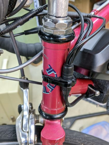
    Terry Bafang - headset cable clip - front
    Terry Bafang – headset cable clip – front

    From the rear:

    Terry Bafang - headset cable clip - rear
    Terry Bafang – headset cable clip – rear

    I later bound the four connectors into a cluster using cable ties to further reduce the clutter and keep them from tapping the top tube.

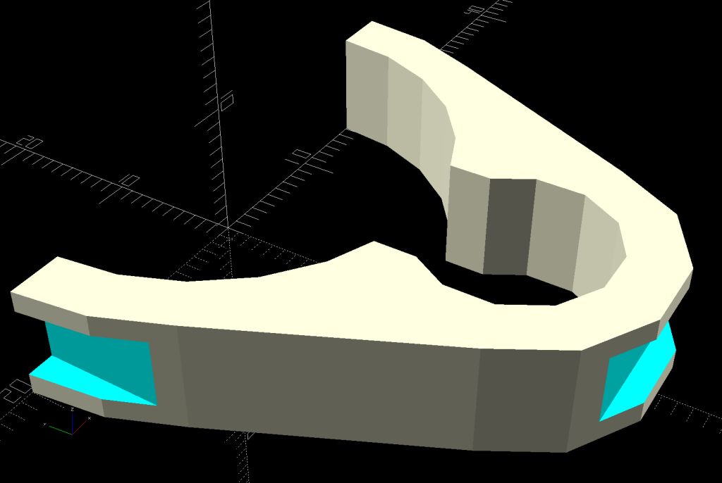
    The clip captures the cable tie in those indents:
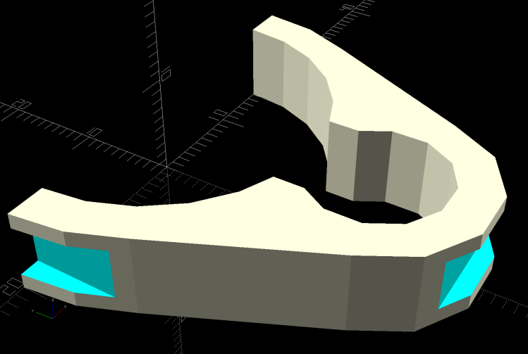
    Terry - Bafang head tube clip - solid model
    Terry – Bafang head tube clip – solid model

    The overhangs require easy cleanup with a square file to get rid of a few droopy threads. Avoid the temptation to print it standing up as an arch, because you want the perimeter threads to go around the whole thing, not across the thinnest sections. Trust me on this.

    The OpenSCAD source code:

    module HeadClip() {
    
    CableOD = Harness[OD];
    
        difference() {
            linear_extrude(height=HeadTube[LENGTH],convexity=10)
                difference() {
                    hull() {
                        circle(d=HeadTube[ID] + 2*WallThick,$fn=FrameSides);
                        translate([0,-(HeadTube[ID] + CableOD)/2])
                            rotate(180/(FrameSides/2))
                                circle(d=CableOD + 2*WallThick,$fn=FrameSides/2);
                    }
                    circle(d=HeadTube[ID] + HoleWindage,$fn=FrameSides);
                    translate([0,-(HeadTube[ID] + CableOD)/2])
                        rotate(180/(FrameSides/2))
                            circle(d=CableOD + HoleWindage,$fn=FrameSides/2);
                    translate([0,-HeadTube[ID]/2])
                        square(0.75*CableOD,center=true);
                    translate([0,HeadTube[ID]])
                        square(2*HeadTube[ID],center=true);
                }
            translate([0,-(HeadTube[ID]/2 + CableOD + WallThick - CableTie.z/2),HeadTube[LENGTH]/2])
                cube([HeadTube[ID],CableTie.z,CableTie.y],center=true);
    
           for (i=[-1,1])
                translate([i*(HeadTube[ID]/2 + WallThick - CableTie.z/2),0,HeadTube[LENGTH]/2])
                    cube([CableTie.z,HeadTube[ID],CableTie.y],center=true);
        }
    }
    

    I briefly thought of holding two pieces together around the head tube with M3 screws, but came to my senses: a cable tie is exactly what you want when holding a cable in place. Right?
  • Bafang BBS02: Terry Brake Sensor

    Bafang BBS02: Terry Brake Sensor

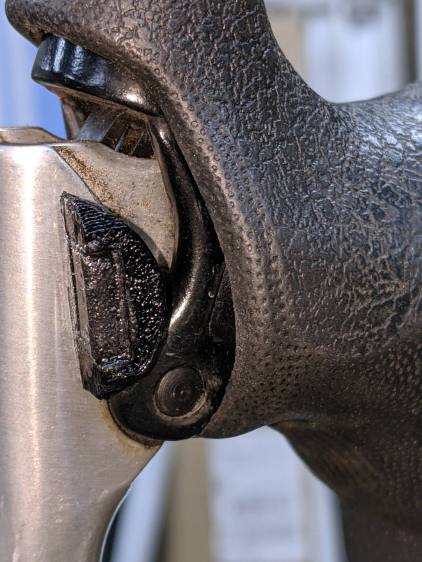
    The old-school “aero” brake levers on Gee’s Terry Symmetry bike have rubberoid cushion covers, so I slid the Bafang brake sensors inside:

    Terry Bafang brake sensor - front
    Terry Bafang brake sensor – front

    They make the grips somewhat wider, but I can’t figure out a less destructive way of installing the things.

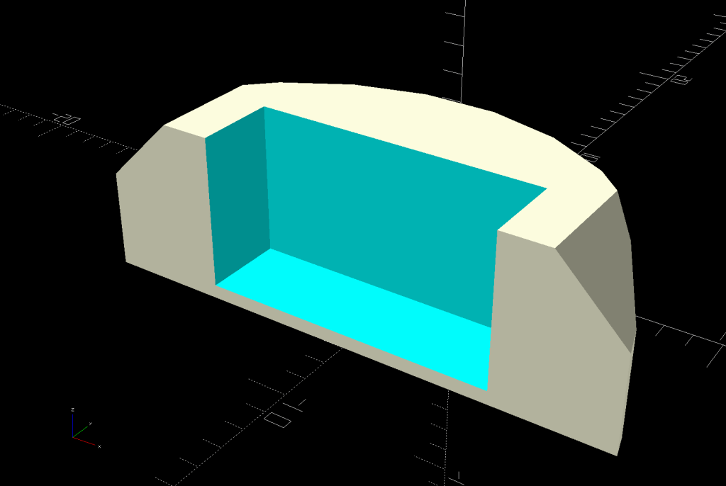
    I glued the magnet inside a holder contoured to fit the space available:

    Terry - Bafang brake sensor - solid model
    Terry – Bafang brake sensor – solid model

    Knocking the corners off makes it much more finger-friendly.

    It’s unobtrusive with the handle released:

    Terry Bafang brake sensor - released
    Terry Bafang brake sensor – released

    When you squeeze the lever, your fingers are nowhere near the magnet:

    Terry Bafang brake sensor - pulled
    Terry Bafang brake sensor – pulled

    The lower edge actually slides along the brake lever housing without touching, but it’s a near thing.

    Those are the same magnets I used for the Bafang brake sensors on Mary’s Tour Easy, once again aligned to aim the strongest volume of the magnetic field toward the sensor. The brake sensors activate just before the pads touch the rims and release with the magnets a few millimeters away from the sensors.

    A complete coat of JB Plastic Bonder urethane adhesive covers each magnet to both isolate it from the weather and conceal the fact that they’re recycled from a power toothbrush.

    Now that I know they work in this position, I must ease adhesive underneath the sensors so they don’t move around under normal hand pressure.

    The OpenSCAD source code snippet:

    module BrakeMagnet() {
    
        Magnet = [10.5,3.0,5.5];
        Plate = 2*ThreadThick;
        BrakeRad = 10.0;            // brake handle curve Radius
        Holder = [2*BrakeRad,7.0,Magnet.z + Plate];
    
    
        difference() {
            intersection() {
                translate([0,-BrakeRad,0])
                    rotate(180/24)
                        cylinder(r=BrakeRad,h=Holder.z,$fn=24);
                translate([0,BrakeRad - Holder.y,Holder.z/2])
                    cube([2*BrakeRad,2*BrakeRad,Holder.z],center=true);
                translate([0,0,-2*BrakeRad/sqrt(2) + Holder.z - 3.0 + BrakeRad])
                    rotate([0,45,0])
                        cube(2*[BrakeRad,2*BrakeRad,BrakeRad],center=true);
            }
            translate([0,Magnet.y/2 - Holder.y - Protrusion/2,Magnet.z/2 + Plate + Protrusion/2])
                cube(Magnet + [0,Protrusion,Protrusion],center=true);
        }
    
    }
    

  • Bafang BBS02: Drop-bar Throttle Adapter

    Bafang BBS02: Drop-bar Throttle Adapter

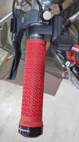
    The Bafang BBS02 package includes a thumb-activated throttle which, like the display, should clamp onto a 22.2 mm handlebar. The one on Mary’s bike fit neatly at the end of the left handgrip:

    Tour Easy grips - left installed
    Tour Easy grips – left installed

    There’s no similar location on a drop-bar bike that doesn’t get in the way, particularly on my friend Gee’s bike with narrow bars.

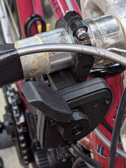
    With a display handlebar adapter in hand, this seemed less awful than anything else I had in mind:

    Bafang Throttle adapter - front view
    Bafang Throttle adapter – front view

    That’s the front view, so it’s on the right side in front of the handlebar. I think it’s usable with either a thumb or fingertips from a hand on the top of the bar. The handlebar lacks tape, as mounting the brake sensors poses a challenge.

    The view from the rear isn’t too revealing:

    Bafang Throttle adapter - rear view
    Bafang Throttle adapter – rear view

    Not too unsightly, but definitely not a standard setup!

  • Bafang BBS02: Drop-bar Display Adapter

    Bafang BBS02: Drop-bar Display Adapter

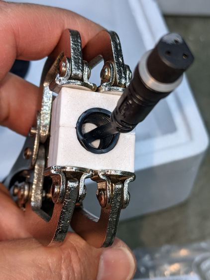
    All of the Bafang BBS02 displays have a compression clamp intended for more-or-less standard 22.2 mm handlebars, as found on typical upright BMX-ish bikes suitable for conversion to e-bikes and, oddly, our Tour Easy recumbents. My friend’s bike has drop-bar handlebars with a 25.4 mm (yes, exactly 1 inch) center section that just isn’t going to fit through that hole.

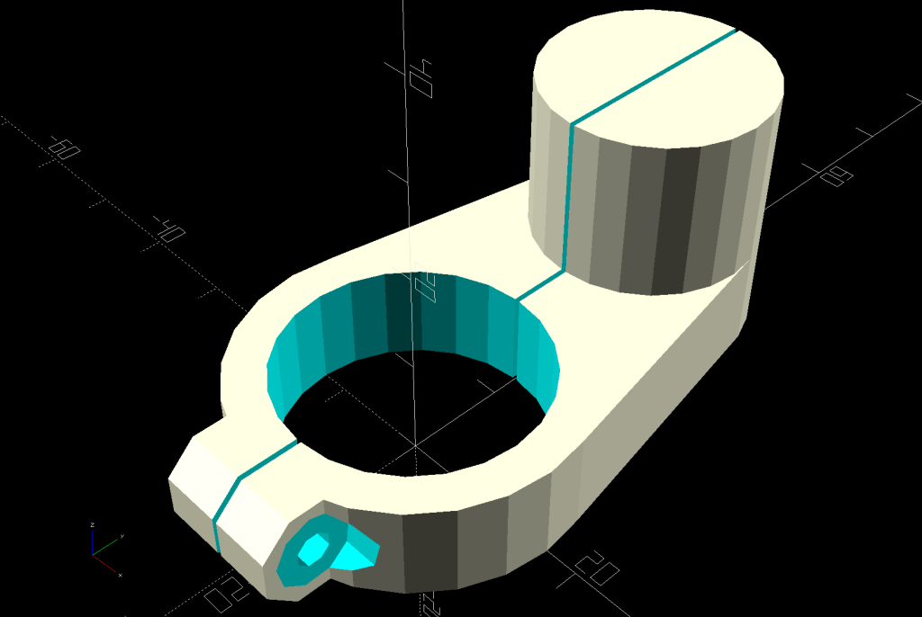
    The least awful solution involved summoning an adapter from the vasty digital deep:

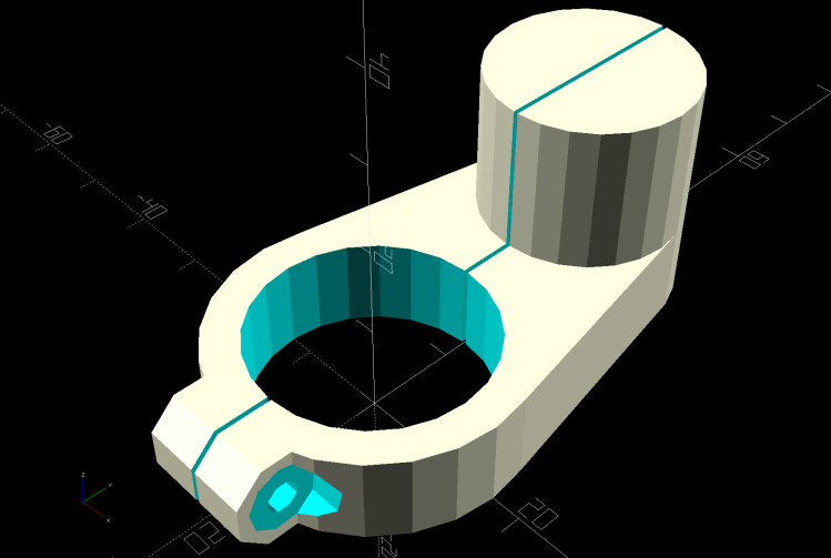
    Display adapter mount - solid model
    Display adapter mount – solid model

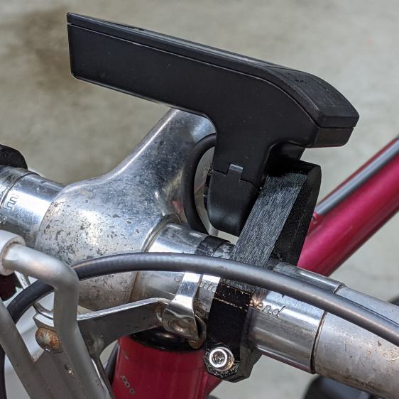
    The hole clamps around the handlebar with an M3 SHCS pulling it snug and the display clamps around the peg to hold everything together:

    Bafang Display adapter - front view
    Bafang Display adapter – front view

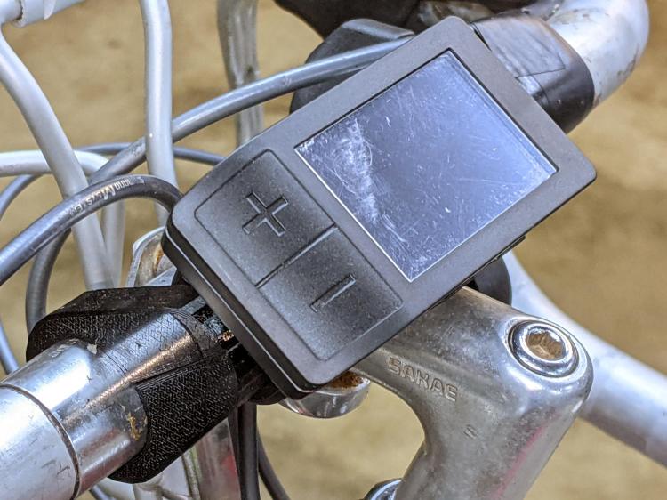
    There’s not much to see from the side:

    Bafang Display adapter - left view
    Bafang Display adapter – left view

    Those scuffs arrived on the protective plastic film!

    The OpenSCAD source code includes some cruft from an idea that didn’t work out quite right:

    HandlebarMax = 1*inch;                      // middle handlebar diameter
    HandlebarMin = 24.0;                        //  .. tape section
    
    BafangClampID = 22.3;                       // new handlebar diameter
    
    
    … snippage …
    
    // Handlebar mount for controller
    
    module DispMount() {
    
    ClampRing = [HandlebarMax,HandlebarMax + 2*WallThick,10.0];
    ClampOffset = (HandlebarMax + BafangClampID)/2 + 6.0;
    
    DispStudLenth = 16.5;
    
    NumSides = 24;
    
    Tilt = 0*atan2((ClampRing[OD] - BafangClampID)/2,ClampOffset);
    echo(str("Tilt: ",Tilt));
    
        difference() {
            union() {
                hull() {
                    cylinder(d=ClampRing[OD],h=ClampRing[LENGTH],$fn=NumSides);
                    translate([0,ClampOffset,0])
                        cylinder(d=BafangClampID,h=ClampRing[LENGTH],$fn=NumSides);
                }
                translate([0,ClampOffset,0])
                    cylinder(d=BafangClampID,h=ClampRing[LENGTH] + DispStudLenth,$fn=NumSides);
                translate([-ClampRing[ID]/4,-(ClampRing[OD]/2),ClampRing[LENGTH]/2])
                    rotate([0,90,0]) rotate(180/8)
                        cylinder(d=ClampRing[LENGTH]/cos(180/8),h=ClampRing[ID]/2,$fn=8);
            }
            cube([Kerf,4*ClampOffset,4*DispStudLenth],center=true);
            translate([0,0,-Protrusion])
                cylinder(d=ClampRing[ID],h=ClampRing[LENGTH] + 2*Protrusion,$fn=NumSides);
            translate([-ClampRing[ID]/2,-(ClampRing[OD]/2),ClampRing[LENGTH]/2])
                rotate([0,90,0]) rotate(180/8)
                    PolyCyl(Screw3[ID],ClampRing[ID],8);
            for (i=[-1,1])
                translate([i*ClampRing[ID]/4,-(ClampRing[OD]/2),ClampRing[LENGTH]/2])
                    rotate([0,i*90,0]) rotate(180/8)
                        PolyCyl(Washer3[OD],ClampRing[ID],$fn=8);
    
            translate([-5,25,EmbossDepth/2 - Protrusion/2])
                rotate(Tilt)
                    cube([4.5,21.5,EmbossDepth + Protrusion],center=true);
    
        }
    
        translate([-5,25,0])
            linear_extrude(height=EmbossDepth)
                rotate(90 + Tilt) mirror([0,1,0])
                  text(text="KE4ZNU",size=3.3,spacing=1.05,font="Bitstream Vera Sans:style=Bold",
                       halign="center",valign="center");
    
    }
    

    It’s rock-solid stable: pushing the buttons doesn’t budge it in the least.

  • Bafang BBS02: Speed Sensor Nut Reshaping

    Bafang BBS02: Speed Sensor Nut Reshaping

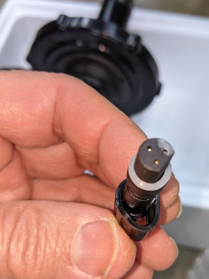
    A Bafang BBS02 (for a friend’s upright bike) arrived with a deformed speed sensor nut:

    Bafang BBS02 - Deformed speed sensor nut - end view
    Bafang BBS02 – Deformed speed sensor nut – end view

    It traveled halfway around the planet while trapped underneath the motor and, if it rode in the top layer or two of containers, the combination of pressure and heat would be irresistible.

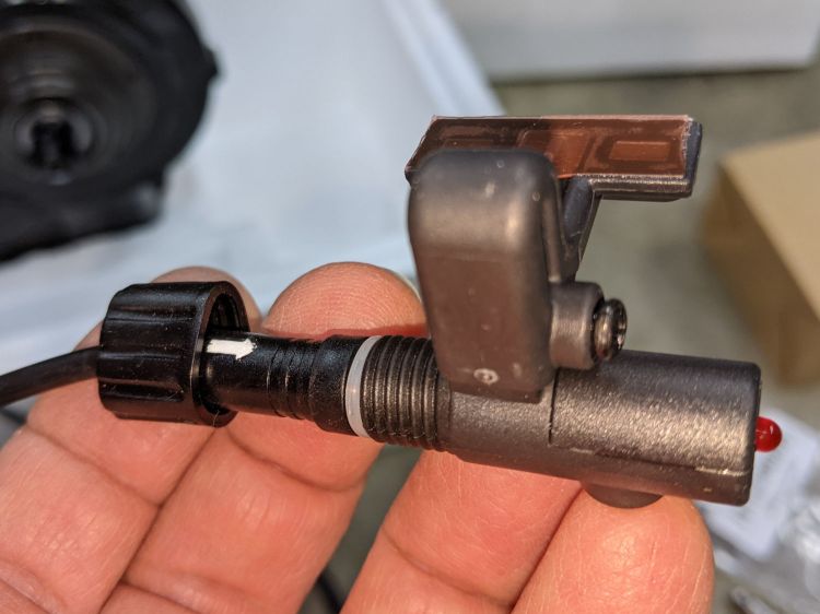
    The plastic was stiff and I couldn’t force the nut over the connector using as much force as seemed reasonable:

    Bafang BBS02 - Deformed speed sensor nut - test assembly
    Bafang BBS02 – Deformed speed sensor nut – test assembly

    On the upside, the nut just compresses the silicone washer between the connector and the sensor to make a waterproof joint, so it need not have perfect threads or a uniform shape. Once the nut is in place, it will likely never be removed and should never bother anyone else.

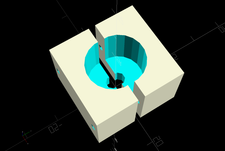
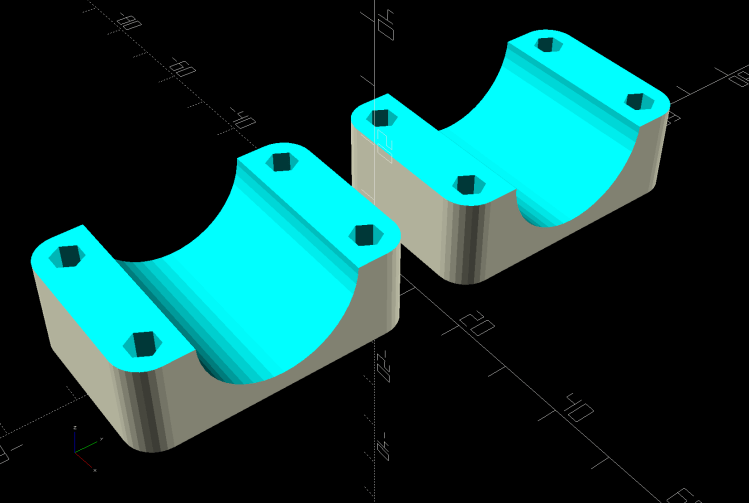
    Being unwilling to apply a hot-air gun near the cable, I decided to try slowly cold-forming the nut inside a mold:

    Sensor Nut mold - solid model
    Sensor Nut mold – solid model

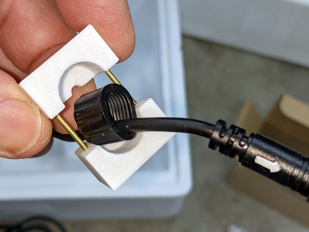
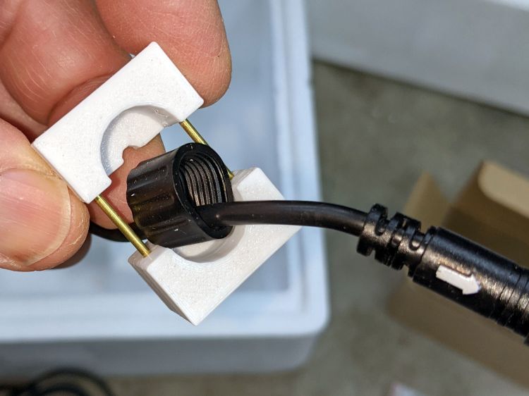
    The gap isn’t a kerf: the two halves meet to form a cylindrical pocket. The smaller holes fit a pair of brass tubes keeping the halves lined up while I arrange things:

    Bafang BBS02 - Deformed speed sensor nut - clamp detail
    Bafang BBS02 – Deformed speed sensor nut – clamp detail

    A pair of swivel-pad clamps apply the pressure:

    Bafang BBS02 - Deformed speed sensor nut - compression clamp
    Bafang BBS02 – Deformed speed sensor nut – compression clamp

    A few days of squashing made it round-er, whereupon I applied the clamp directly against the remaining high point with the other side cradled in the mold. It still doesn’t slide over the connector body, but I’m not in a rush.

    Bafang tech support generously sent a speed sensor extension cable from which I can extract a good nut, which will require cutting and splicing the cable from the motor.

    I’m still hoping gentle suasion will prevail.

    The OpenSCAD source code tucks into the overall file producing various useful bits:

    // Mold to reshape speed sensor nut
    
    SensorNut = [0,14.4,13.0];
    SensorMold = [SensorNut[OD] + 2*WallThick,SensorNut[OD] + 2*WallThick,SensorNut[LENGTH] + WallThick];
    MoldSides = 20;
    RodOD = 1.6;
    
    module NutMoldBlock() {
    
        difference() {
    
            translate([0,0,SensorMold.z/2])
                cube(SensorMold,center=true);
    
            translate([0,0,WallThick])
                rotate(180/MoldSides)
                    PolyCyl(SensorNut[OD],2*SensorNut[LENGTH],MoldSides);
            translate([0,0,-Protrusion])
                rotate(180/8)
                    PolyCyl(SpeedOD,2*SensorMold.z,8);
    
            for (i=[-1,1])
                translate([i*(SensorMold.x/2 - WallThick/2),SensorMold.y,SensorMold.z/2])
                    rotate([90,0,0])
                        PolyCyl(RodOD,2*SensorMold.y,6);
        }
    }
    
    module NutMold() {
        gap = 1.0;
    
        for (j=[-1,1])
            translate([0,j*gap,0])
                intersection() {
                    translate([0,j*SensorMold.y,0])
                        cube(2*SensorMold,center=true);
                    NutMoldBlock();
                }
    }
    
    … snippage …
    
    if (Layout == "NutMold")
        NutMold();


    I haven’t worked on a safety bike in years!

  • Dripworks Mainline Pipe Clamp

    Dripworks Mainline Pipe Clamp

    This is laid in against a need I hope never occurs:

    Dripworks 0.75 inch pipe clamp
    Dripworks 0.75 inch pipe clamp

    It’s intended to clamp around one of the Dripworks mainline pipes carrying water from the pressure regulator to the driplines in the raised beds, should an errant shovel or fork find the pipe.

    It descends from a long line of soaker hose clamps, with a 25 mm ID allowing for a silicone tape wrap as a water barrier.

    The solid model has no surprises:

    Dripworks Mainline Clamp - build view
    Dripworks Mainline Clamp – build view

    The OpenSCAD source code as a GitHub Gist:

    // Dripworks 3/4 inch mainline clamp
    // Ed Nisley KE4ZNU 2021-06
    Layout = "Build"; // [Hose,Block,Show,Build]
    HoseOD = 25.0;
    TestFit = false; // true to build test fit slice from center
    //- Extrusion parameters must match reality!
    /* [Hidden] */
    ThreadThick = 0.25;
    ThreadWidth = 0.40;
    HoleWindage = 0.2;
    Protrusion = 0.1; // make holes end cleanly
    inch = 25.4;
    function IntegerMultiple(Size,Unit) = Unit * ceil(Size / Unit);
    ID = 0;
    OD = 1;
    LENGTH = 2;
    //———-
    // Dimensions
    // Hose lies along X axis
    Hose = [200,HoseOD,HoseOD]; // X = longer than anything else
    NumScrews = 2; // screws along each side of cable
    WallThick = 3.0; // Thinnest printed wall
    PlateThick = 1.5; // Stiffening plate thickness
    // 8-32 stainless screws
    Screw = [4.1,8.0,50.0]; // OD = head LENGTH = thread length
    Washer = [4.4,9.5,1.0];
    Nut = [4.1,9.7,3.3];
    Block = [30.0,Hose.y + 2*Washer[OD],HoseOD + 2*WallThick]; // overall splice block size
    echo(str("Block: ",Block));
    ScrewMinLength = Block.z + 2*PlateThick + 2*Washer.z + Nut.z; // minimum screw length
    echo(str("Screw min length: ",ScrewMinLength));
    Kerf = 1.0; // cut through middle to apply compression
    CornerRadius = Washer[OD]/2;
    ScrewOC = [(Block.x – 2*CornerRadius) / (NumScrews – 1),
    Block.y – 2*CornerRadius,
    2*Block.z // ensure complete holes
    ];
    echo(str("Screw OC: x=",ScrewOC.x," y=",ScrewOC.y));
    //———————-
    // Useful routines
    module PolyCyl(Dia,Height,ForceSides=0) { // based on nophead's polyholes
    Sides = (ForceSides != 0) ? ForceSides : (ceil(Dia) + 2);
    FixDia = Dia / cos(180/Sides);
    cylinder(d=(FixDia + HoleWindage),h=Height,$fn=Sides);
    }
    // Hose shape
    // This includes magic numbers measured from reality
    module HoseProfile() {
    NumSides = 12*4;
    rotate([0,-90,0])
    translate([0,0,-Hose.x/2])
    resize([Hose.z,Hose.y,0])
    cylinder(d=Hose.z,h=Hose.x,$fn=NumSides);
    }
    // Outside shape of splice Block
    // Z centered on hose rim circles, not overall thickness through center ridge
    module SpliceBlock() {
    difference() {
    hull()
    for (i=[-1,1], j=[-1,1]) // rounded block
    translate([i*(Block.x/2 – CornerRadius),j*(Block.y/2 – CornerRadius),-Block.z/2])
    cylinder(r=CornerRadius,h=Block.z,$fn=4*8);
    for (i = [0:NumScrews – 1], j=[-1,1]) // screw holes
    translate([-(Block.x/2 – CornerRadius) + i*ScrewOC.x,
    j*ScrewOC.y/2,
    -(Block.z/2 + Protrusion)])
    PolyCyl(Screw[ID],Block.z + 2*Protrusion,6);
    cube([2*Block.x,2*Block.y,Kerf],center=true); // slice through center
    }
    }
    // Splice block less hose
    module ShapedBlock() {
    difference() {
    SpliceBlock();
    HoseProfile();
    }
    }
    //———-
    // Build them
    if (Layout == "Hose")
    HoseProfile();
    if (Layout == "Block")
    SpliceBlock();
    if (Layout == "Show") {
    difference() {
    SpliceBlock();
    HoseProfile();
    }
    color("Green",0.25)
    HoseProfile();
    }
    if (Layout == "Build") {
    SliceOffset = TestFit && !(NumScrews % 2) ? ScrewOC.x/2 : 0;
    intersection() {
    translate([SliceOffset,0,Block.z/4])
    if (TestFit)
    cube([ScrewOC.x/2,4*Block.y,Block.z/2],center=true);
    else
    cube([4*Block.x,4*Block.y,Block.z/2],center=true);
    union() {
    translate([0,0.6*Block.y,Block.z/2])
    ShapedBlock();
    translate([0,-0.6*Block.y,Block.z/2])
    rotate([0,180,0])
    ShapedBlock();
    }
    }
    }

  • Microscope Stage Positioner: Rigid MakerBeam Edition

    Microscope Stage Positioner: Rigid MakerBeam Edition

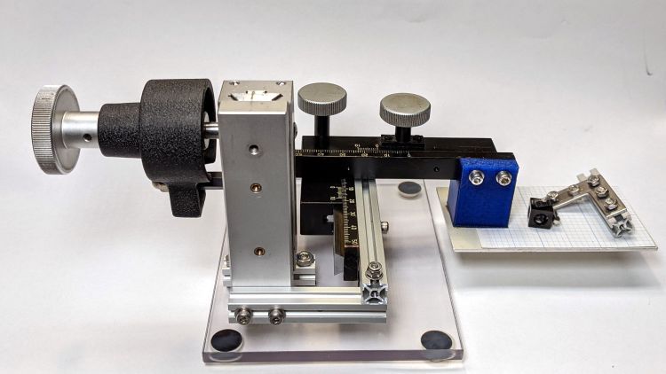
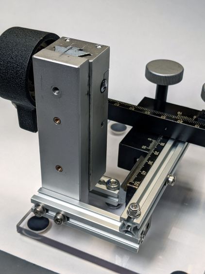
    Rebuilding the XYZ stage positioner with MakerBeam aluminum struts, but without the steel brackets, produce a much more rigid result:

    Microscope Stage Positioner - rigid Makerbeam
    Microscope Stage Positioner – rigid Makerbeam

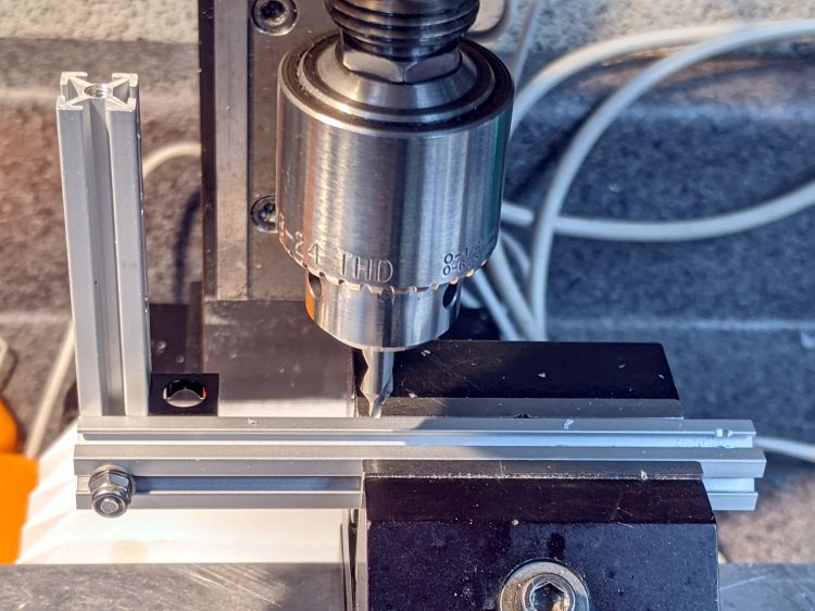
    This requires drilling holes through the extrusions:

    Microscope Stage Positioner - Makerbeam drilling
    Microscope Stage Positioner – Makerbeam drilling

    Running the center drill down until it just nicks the sides produces enough of a pilot hole through the center section to capture the 3 mm drill. If I had to drill enough holes to make a fixture worthwhile, I could probably eliminate the divots.

    Two more holes + epoxied M3 brass inserts attached the 60 mm beam directly to the Z Axis stage, thereby eliminating the vertical beam and a steel bracket:

    Microscope Stage Positioner - Makerbeam joints
    Microscope Stage Positioner – Makerbeam joints

    The M3 SHCS attaching the 100 mm beam goes through both beams. I think you could get the same result with a Tee Nut or a 12 mm Square Head bolt, should you have those lying around and don’t want to drill another hole. The Corner Cube screwed into both beams prevents rotation and helps ensure perpendicularity.

    The Y stage now attaches directly to the beam, rather than through a pair of Corner Cubes, because I realized I wasn’t ever going to adjust its position.

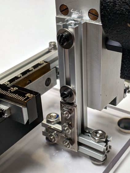
    The Z Axis stage stands on the plastic plate through a hellish mixture of metric and USA-ian screws. Basically, the 6-40 screws into the stage were long enough, the 6-32 screws through the plate fit the existing holes, and M3 screws are for MakerBeam:

    Microscope Stage Positioner - Z Axis base
    Microscope Stage Positioner – Z Axis base

    To my utter astonishment, the threads in the end of the vertical beam had the proper alignment to let a Square Head bolt snug the beam against the 40 mm beam on the plate. As a result, the L Bracket just prevents the vertical beam from turning on the screw and the combination is as rigid as you (well, I) could want.

    The 40 mm beam has two spurious holes, because I thought I could avoid drilling another hole in the baseplate. Nobody will ever notice.

    After squaring and tightening everything, the 100 mm beam along the Y Axis is now horizontal within 0.2 mm and the X Axis is horizontal to better than I can measure.

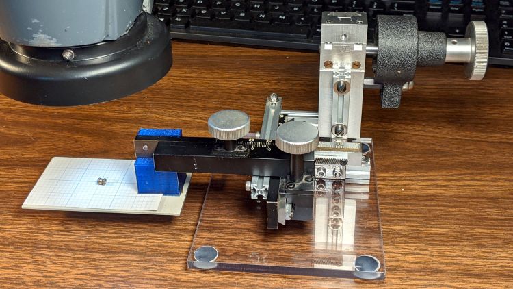
    It’s definitely Good Enough™ for me:

    Microscope Stage Positioner - in use
    Microscope Stage Positioner – in use

    Remember, nothing exceeds like excess …