|
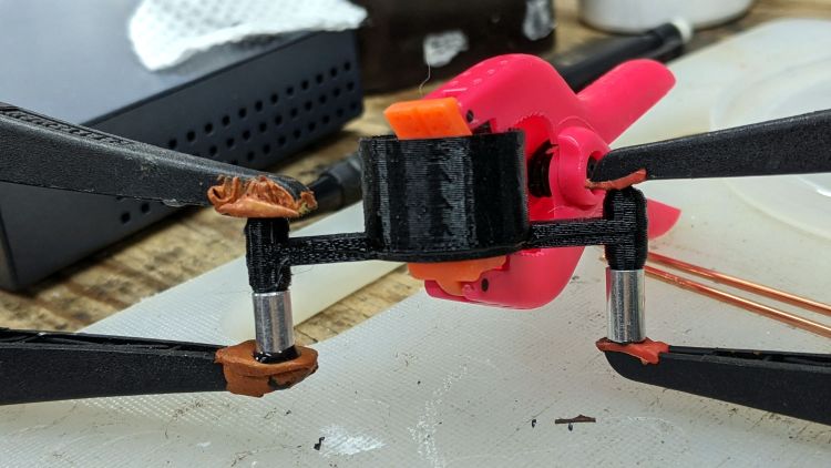
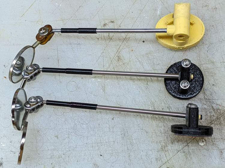
// Pride wheelchair brake lever mods |
|
// Ed Nisley KE4ZNU 2020-11 |
|
|
|
/* [Layout options] */ |
|
|
|
Layout = "Build"; // [Build, Show, Fit, TabCap, Handle, Knob, Support] |
|
|
|
// Hold up the knob's inside |
|
Support = true; |
|
|
|
/* [Extrusion parameters] */ |
|
|
|
/* [Hidden] */ |
|
|
|
ThreadThick = 0.25; |
|
ThreadWidth = 0.40; |
|
|
|
HoleWindage = 0.2; |
|
|
|
function IntegerMultiple(Size,Unit) = Unit * ceil(Size / Unit); |
|
function IntegerLessMultiple(Size,Unit) = Unit * floor(Size / Unit); |
|
|
|
Protrusion = 0.1; // make holes end cleanly |
|
|
|
inch = 25.4; |
|
|
|
ID = 0; |
|
OD = 1; |
|
LENGTH = 2; |
|
|
|
//———————- |
|
// Useful routines |
|
|
|
module PolyCyl(Dia,Height,ForceSides=0) { // based on nophead's polyholes |
|
|
|
Sides = (ForceSides != 0) ? ForceSides : (ceil(Dia) + 2); |
|
|
|
FixDia = Dia / cos(180/Sides); |
|
|
|
cylinder(r=(FixDia + HoleWindage)/2,h=Height,$fn=Sides); |
|
} |
|
|
|
|
|
|
|
//* [Basic dimensions] */ |
|
|
|
WallThick = 4.0; // min wall thickness |
|
|
|
Screw = [3.0,5.5,20.0]; // thread, head, length under head |
|
Insert = [3.0,4.1,8.0]; // thread, knurl, length |
|
|
|
//———————- |
|
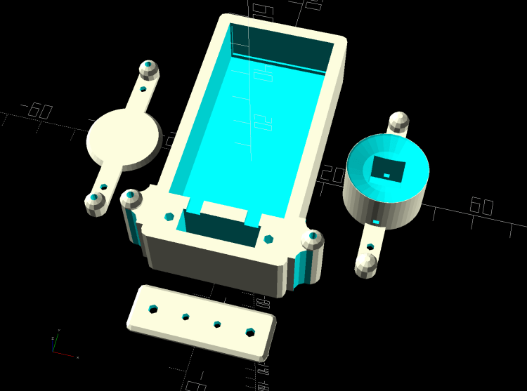
// Brake tab cap |
|
|
|
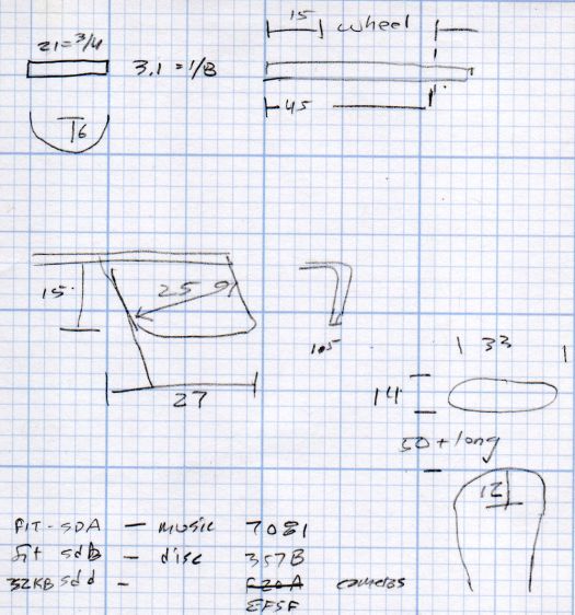
BrakeTab = [15,21,3.1]; // length to wheel, width, thickness |
|
BrakeTabSagitta = 8.0; // height of curved endcap |
|
|
|
CapOAL = [BrakeTab.y + 2*WallThick,BrakeTab.y + 2*WallThick,BrakeTab.z + 2*WallThick]; |
|
|
|
module TabCap() { |
|
|
|
difference() { |
|
rotate(180/8) |
|
cylinder(d=CapOAL.y,h=CapOAL.z,center=true,$fn=8); |
|
translate([BrakeTab.x/2,0,0]) |
|
cube(BrakeTab,center=true); |
|
rotate(180/8) |
|
cylinder(d=BrakeTab.y/cos(180/8),h=BrakeTab.z,center=true,$fn=8); |
|
} |
|
} |
|
|
|
//———————- |
|
// Brake lever handle |
|
// Soft covering with rounded sides that we square off for simplicity |
|
|
|
HandleRibs = [15,34,14]; // ignoring slight taper from end |
|
HandleCore = [50.0,24.0,12.0]; // straight section of lever to top of ribs |
|
HandleTipWidth = 30.0; // ignoring actual sector height |
|
|
|
module Handle() { |
|
|
|
union() { |
|
hull() { |
|
rotate(180/8) |
|
cylinder(d=HandleTipWidth/cos(180/8),h=HandleCore.z,center=true,$fn=8); |
|
translate([-HandleCore.x/2,0,0]) |
|
cube(HandleCore,center=true); |
|
} |
|
translate([-(3*HandleCore.x/2 – Protrusion),0,0]) // extend base for ball trimming |
|
cube(HandleCore,center=true); |
|
translate([-HandleRibs.x/2,0,0]) |
|
cube(HandleRibs,center=true); |
|
} |
|
|
|
} |
|
|
|
//———————- |
|
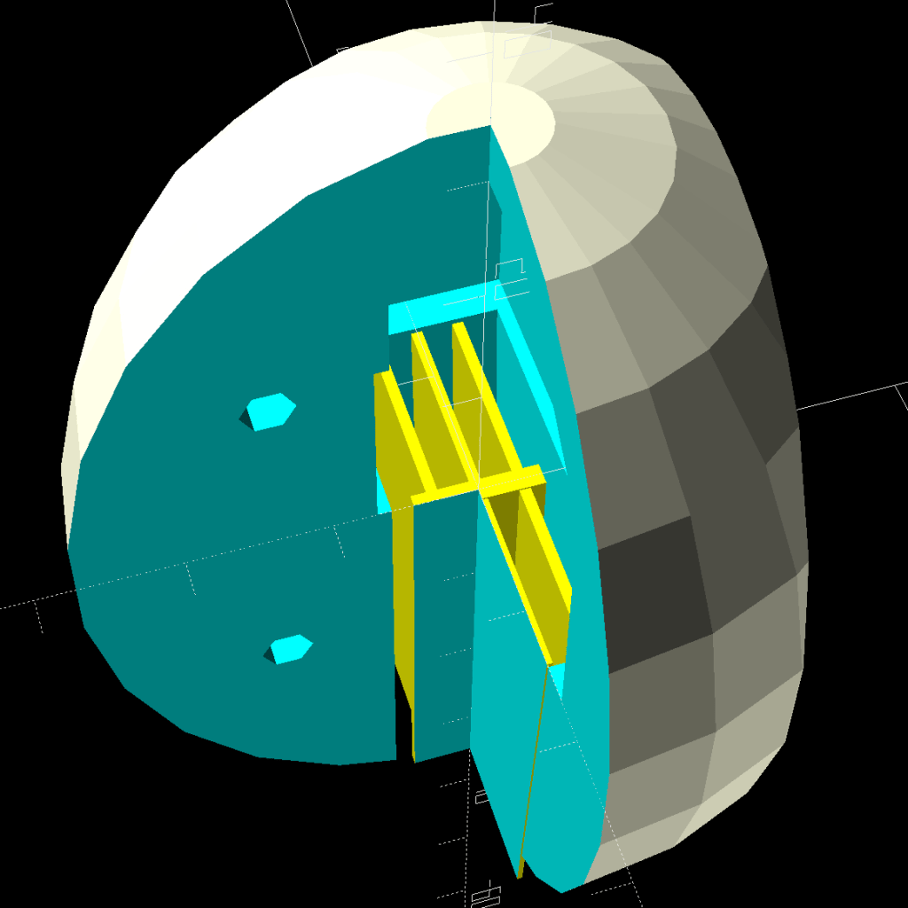
// Support structure for handle cavity inside knob |
|
// Totally ad-hoc tweakage |
|
// Remember it's lying on its side to match the handle |
|
|
|
NumRibs = 2 + 1; // must be odd |
|
RibSpace = floor(HandleCore.z/(NumRibs + 1)); |
|
|
|
module KnobSupport() { |
|
|
|
color("Yellow") { // support overlaps in the middle |
|
render(convexity=3) |
|
intersection() { |
|
for (k=[-1,1]) |
|
translate([0,k*ThreadThick,0]) // shrink inward to break adhesion |
|
Handle(); |
|
|
|
translate([(HandleCore.x – HandleRibs.x)/2 – HandleCore.x – Protrusion,0,0]) |
|
cube([HandleCore.x – HandleRibs.x,HandleRibs.y,HandleCore.z],center=true); |
|
|
|
union() |
|
for (k=[-floor(NumRibs/2):floor(NumRibs/2)]) |
|
translate([0,0,k* RibSpace]) |
|
cube([2*HandleCore.x,HandleRibs.y,2*ThreadWidth],center=true); |
|
} |
|
|
|
translate([(HandleCore.x – HandleRibs.x)/2 – HandleCore.x,0,0]) |
|
cube([HandleCore.x – HandleRibs.x,4*ThreadWidth,NumRibs*RibSpace],center=true); |
|
} |
|
} |
|
|
|
//———————- |
|
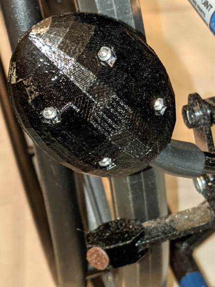
// Brake handle knob |
|
// Largely built with magic numbers |
|
// Includes support because it's not really optional |
|
|
|
KnobOD = 55.0; |
|
KnobOffset = HandleRibs.x/1; |
|
|
|
KnobSides = 2*4*3; |
|
|
|
module Knob() { |
|
|
|
difference() { |
|
hull() { |
|
resize([0,HandleRibs.y + 4*WallThick,HandleCore.x + HandleTipWidth/2 + WallThick]) |
|
sphere(d=KnobOD,$fn=KnobSides); |
|
} |
|
|
|
translate([0,0,KnobOffset]) |
|
rotate([0,-90,0]) |
|
Handle(); |
|
|
|
for (i=[-1,1],k=[-1,1]) |
|
translate([i*KnobOD/4,0,k*KnobOD/4]) { |
|
rotate([90,0,0]) |
|
PolyCyl(Insert[OD],1.5*Insert[LENGTH],6); |
|
translate([0,-Screw[LENGTH]/2,0]) |
|
rotate([-90,0,0]) |
|
PolyCyl(Screw[ID],KnobOD,6); |
|
translate([0,Screw[LENGTH] – Insert[LENGTH],0]) |
|
rotate([-90,0,0]) |
|
PolyCyl(Screw[OD],KnobOD,6); |
|
} |
|
} |
|
|
|
if (Support) |
|
translate([0,0,KnobOffset]) |
|
rotate([0,-90,0]) |
|
KnobSupport(); |
|
|
|
} |
|
|
|
//———————- |
|
// Lash it together |
|
|
|
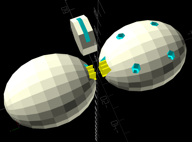
if (Layout == "TabCap") { |
|
TabCap(); |
|
} |
|
|
|
if (Layout == "Handle") { |
|
Handle(); |
|
} |
|
|
|
if (Layout == "Support") { |
|
KnobSupport(); |
|
} |
|
|
|
if (Layout == "Knob") { |
|
Knob(); |
|
} |
|
|
|
if (Layout == "Show") { |
|
translate([60,0,0]) |
|
TabCap(); |
|
Knob(); |
|
} |
|
|
|
if (Layout == "Fit") { |
|
translate([60,0,0]) |
|
difference() { |
|
TabCap(); |
|
translate([0,0,CapOAL.z/2]) |
|
cube(CapOAL,center=true); |
|
} |
|
difference() { |
|
Knob(); |
|
translate([KnobOD + KnobOD/4,0*KnobOD,0]) |
|
cube(2*KnobOD,center=true); |
|
translate([-KnobOD,-KnobOD,0]) |
|
cube(2*KnobOD,center=true); |
|
} |
|
} |
|
|
|
if (Layout == "Build") { |
|
translate([KnobOD/2,0,(CapOAL.y*cos(180/8))/2]) |
|
rotate([0,-90,90]) |
|
TabCap(); |
|
|
|
for (j=[-1,1]) |
|
translate([0,-j*0.75*HandleCore.x,0]) |
|
difference() { |
|
rotate([j*90,0,0]) |
|
Knob(); |
|
translate([0,0,-KnobOD]) |
|
cube(2*KnobOD,center=true); |
|
} |
|
|
|
} |