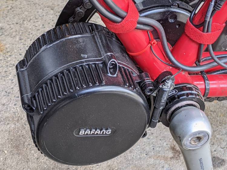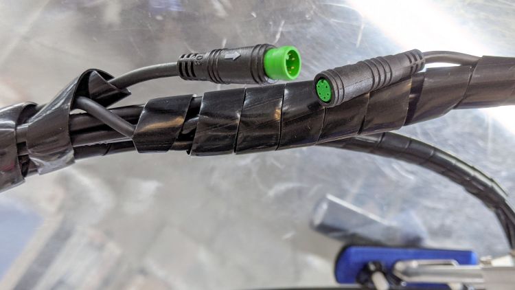
As mentioned earlier, the Bafang brake sensors on Mary’s Tour Easy require a magnet on the brake levers to activate the switches. They arrived with disk magnets that did not suit the levers, so I used neodymium “bar magnets”:
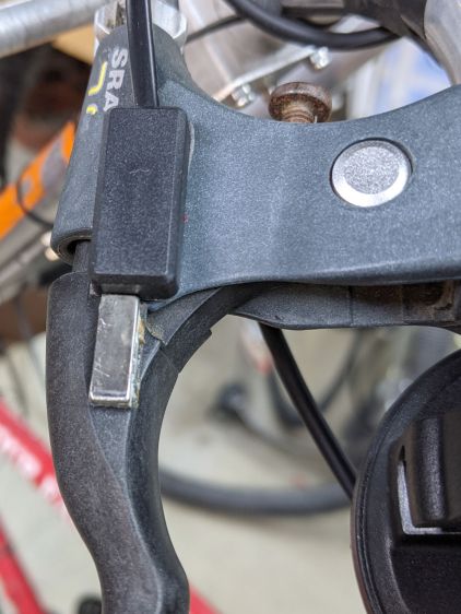
That worked for a few rides, but the alignment turned out to be entirely too critical, because the magnetization is through the bar’s thin dimension, rather than along its length, making the field weakest in the direction of the switch.
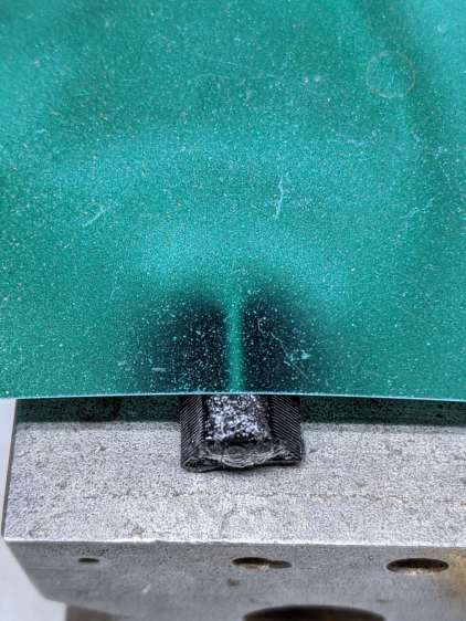
Magnetic field visualization film shows the field null along the thin edge of the bar:
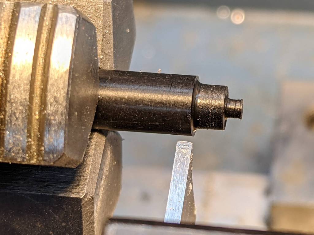
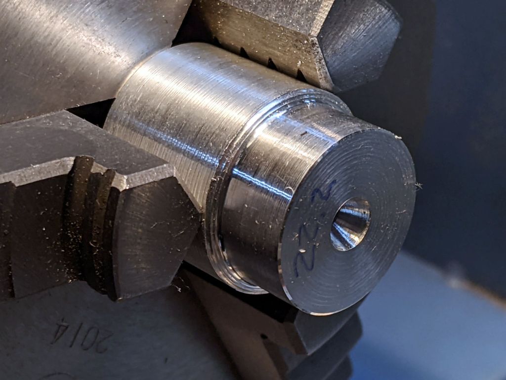
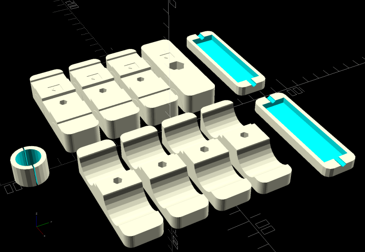
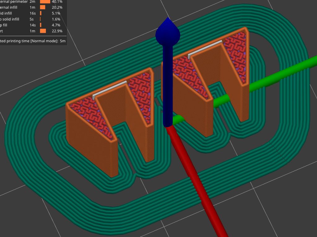
That’s a slightly shorter magnet from a different toothbrush head, cemented edgewise into a holder conjured from the vasty digital deep:

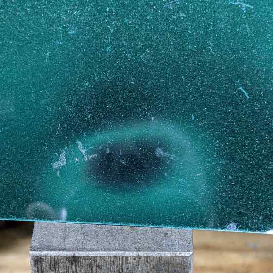
The field is much more uniform on the flat side of the bar:
Some double-sided foam tape snuggles the sensor and the magnet together on the brake lever:
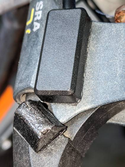
I coated the magnet with JB Plastic Bonder urethane adhesive in the hope of filling any gaps in its nickel coating caused while extricating it from the toothbrush head.
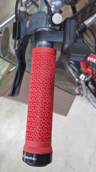
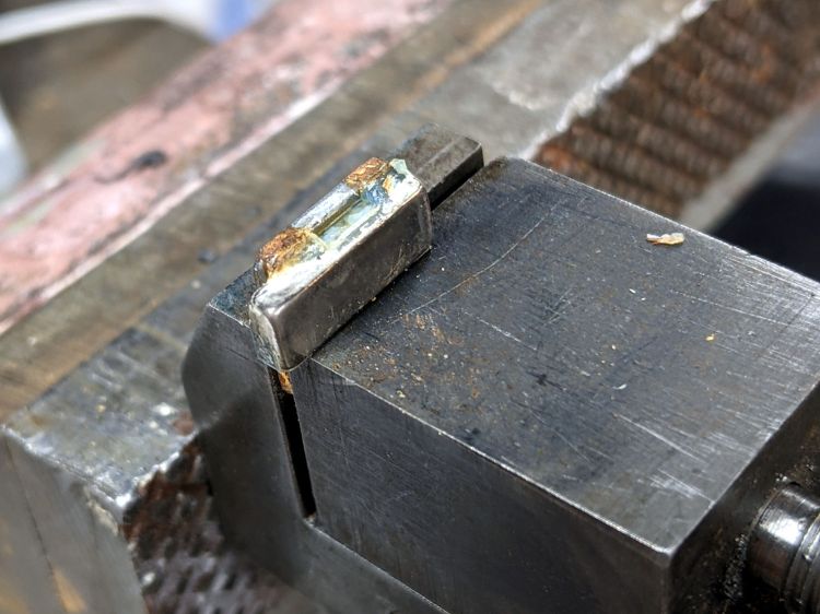
The rusty screw head in the upper right positions the lever at the proper distance from the grip to suit Mary’s hand. An earlier version of the holder shows the alignment:
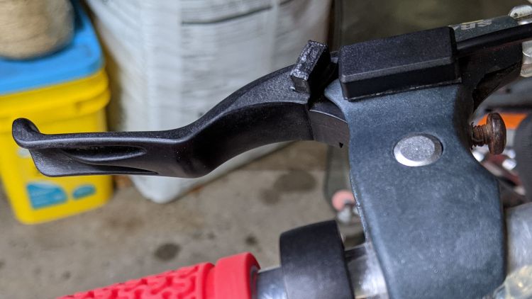
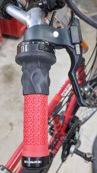
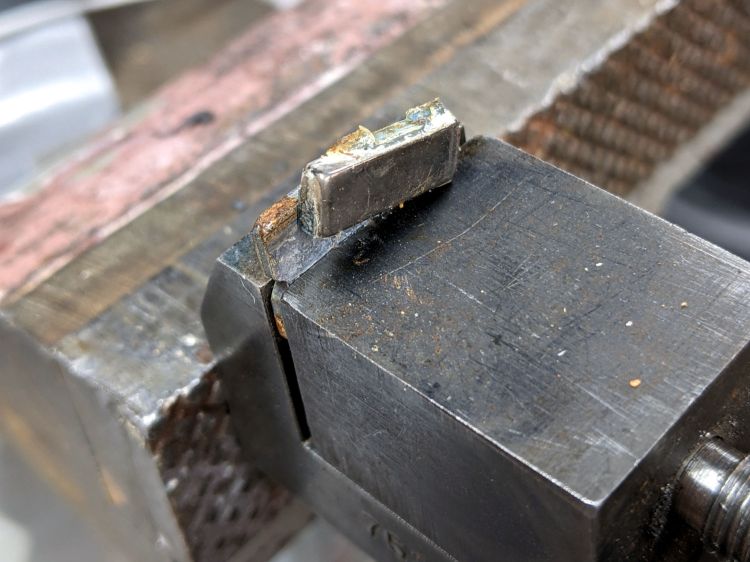
The switch trips (opens) with the lever roughly parallel to the grip, again with the earlier holder:
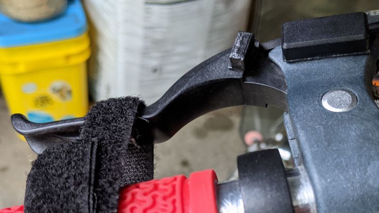
A detailed view of the gap with the lever at the tripped position:

The levers have enough travel to prevent accidental trips due to light finger pressure, which turned out to be a problem with the original end-on alignment.
The brake pads don’t quite touch the rim when the switch trips, so the motor has plenty of time to shut off before the brakes take effect. It also stops when the pedals stop turning, so we should not see any disagreement between motor and brakes as to the bike’s momentum.
The wider base on the new mounts makes them much more stable on the levers, although I don’t like having them stick up so far. Mounting everything underneath the levers would look better, but any problems will be more obvious with everything in plain sight.
I may affix the magnets directly to the levers with Plastic Bonder if the foam tape doesn’t live up to its reputation. Removing them would be more challenging; a shot with a small chisel should suffice.