What a difference 100 µm can make:
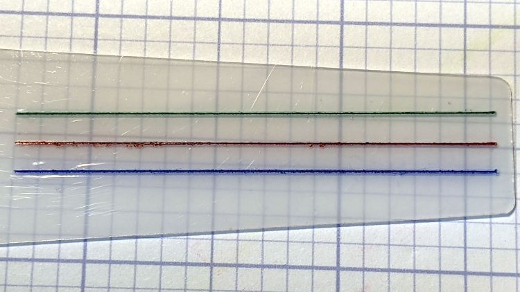
All three hairlines have 0.3 mm depth of cut, with the spindle running at 10 kRPM and the cut proceeding at 24 inch/min = 600 mm/min. All three cuts went through a strip of water + detergent along their length, which seems to work perfectly.
The cuts start on the left side:
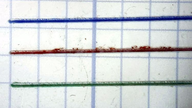
I cut the red hairline through the PET cursor’s protective film to confirm doing it that way is a Bad Idea™; the gnarly appearance is sufficient proof.
The cuts end on the right:
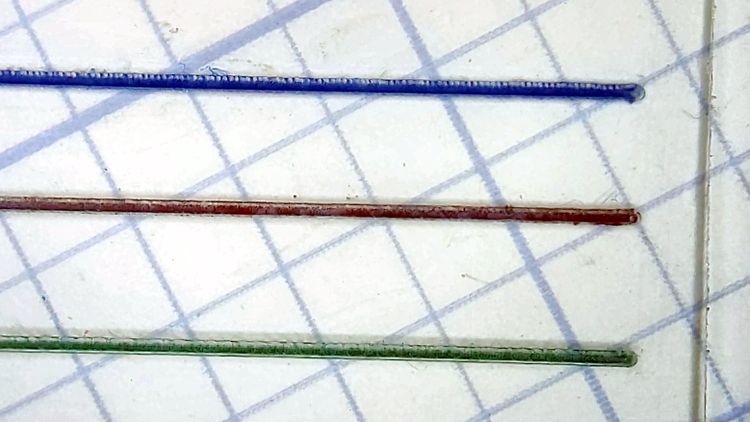
Eyeballometrically, the cuts are the same depth on both ends, with a slight texture difference at the start as the X axis ramps up to full speed.
They’d be a bit stout on an old-school engraved slide rule, but look just fine laid against a laser-printed Homage Tek Circuit Computer:
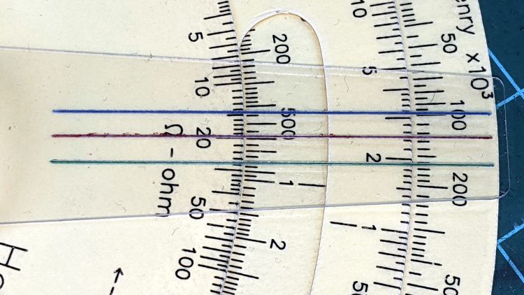
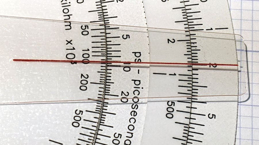
Flushed with success, here’s a fresh-cut red hairline in action:
The end of the cursor sticks out 1 mm over the rim of the bottom deck, because I wanted to find out whether that would make it easier to move. It turns out the good folks at Tek knew what they were doing; a too-long cursor buckles too easily.
The trick will be touching off the V tool accurately enough on the cursor surface to get the correct depth of cut. The classic machinist’s technique involves a pack of rolling papers, which might be coming back into fashion here in NY.

Comments
6 responses to “Tek CC Milled Cursor: MVP”
This looks good so maybe moot, but I wonder if a heated object – wire or milled prominence could melt a nice line into the plastic.
The trouble with a melted hairline is the glossy interior not holding pigment / dye / color any better than the surrounding cursor. I produced something like that with the uncooled cutter; the junk along the edges of the trench was just a bonus. [sigh]
I haven’t been able to find any references describing how K&E / Pickett made their hairlines, but they probably used a simple cutter on something like a shaper: drag cutter across cursor, add pigment, wipe off, done. If only I had that kind of tech and knew how to use it …
At these scales in plastic, surely the mill makes a perfectly cromulent shaper?
The rotating bit normally cuts / gouges / bites on the spinward side of the flat, rather than the bottom, so it’s probably suboptimal for a shaper bit. Maybe stoning (“diamond filing”) a straight edge on that teeny tiny tip would help?
On the other paw, much of what I do around here is suboptimal. I should just jam the spindle with the bit’s flat side facing into the cut and see what happens.
Thanks for the suggestion …
I’m curious as to the jig to punch and center the disks then to rivet them… I’ve used scotch tape and a center dot, then melt the center hole with a solder iron, while the set is clamped in a vise and used a pop-rivet.
but alignment never seems to be better than 99.5 : 100 – aaargh!
With paper disks, I just line up the punch on the outline and whack it with a hammer. This certainly isn’t perfect, but the overall (lack of) concentricity doesn’t seem to make much difference: the filter caps probably have worse tolerances than the numeric results!