Engraving a 0.2 mm deep hairline in a Tek Circuit Computer cursor showed the fixture had a bit of a tilt:
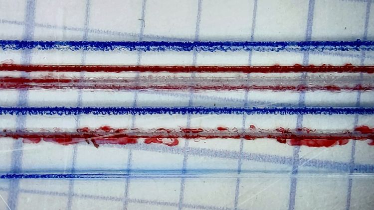
The bottom blue hairline started with a good cut and ended with the V tool skating along the surface without cutting. The raggedy red one just above it is what happens when you (well, I) try engraving a hairline through Kapton tape without coolant; just don’t do that thing.
The 3D printed fixture holding the cursor came from a neurotically aligned Makergear M2 and the tooling plate has never had much attention to its alignment, so I figured the tilt probably came from crud between the tooling plate and the Sherline’s X axis table, with the printed fixture contributing zilch to the problem.
Which turned out to be the case. Scraping a few flakes from the bottom of the plate and top of the table, dissolving old crud with water + alcohol, and passing a file over both surfaces definitely made a difference. I converted a sheet of 0.1 mm laminating plastic film into a pad by punching holes for the T-nuts:

Snugging the tooling plate down produced perfect alignment along the length of three 0.3 mm deep hairlines:

That was surprisingly easy …

Comments
One response to “Sherline Tooling Plate Re-Alignment”
[…] What a difference 100 µm can make: […]