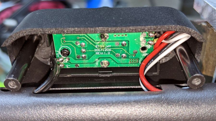
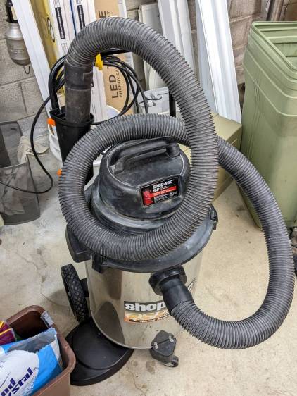
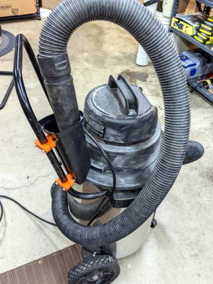
Shortly after acquiring the Greatest ShopVac, I zip-tied half a foot of cardboard tube to the handle to corral the nozzle and keep the ungainly hose from sprawling across the floor. While disembowling the Ottlite into a mini-lathe light, the plastic trim joining the baseplate to the vertical tube cried out to become a nozzle caddy:
It was exactly the right size and shape (by my admittedly slack standards) to hold the nozzle, plus being destined for the trash, so all it needed was a pair of clamp brackets conjured from the vasty digital deep:
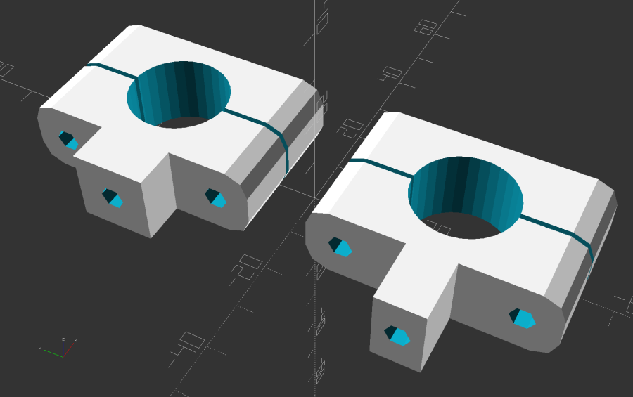
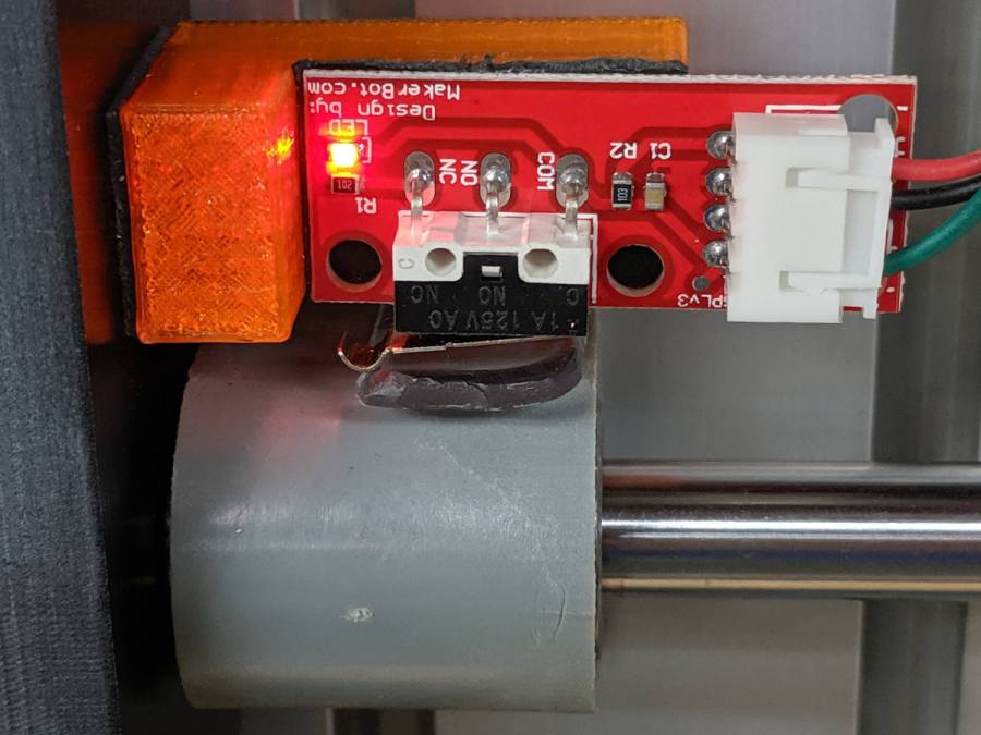
The bosses fit into a tapered slot along what was the rear side, with a pair of 4 mm holes at each end for screws into threaded brass inserts epoxied into the brackets:

They obviously descend from the many clamp mounts I’ve made for everything from garden hoses to bike running lights. A pair of 4 mm SHCS squish the clamp around the handle, with a strip of electrical tape improving plastic-to-metal griptivity:
The clearance just barely allows a nylock nut atop a washer and you’ll want to trim those 40 mm screws to an exact fit, but it came out pretty well.
The original dimension doodle with some modeling ideas that didn’t survive more thinking:
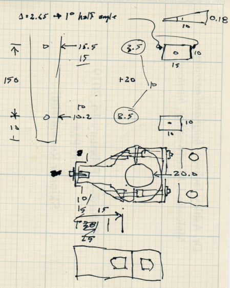
A more detailed doodle with brass inserts instead of the nylock nuts and an aluminum spreader plate that was obviously not necessary:

In retrospect, the inserts would make more sense.
The angle doodles convinced me not to bother modeling either the slot’s taper along its length or its mold draft.
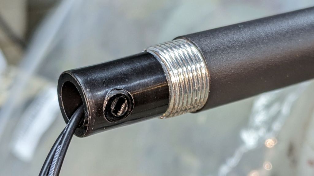
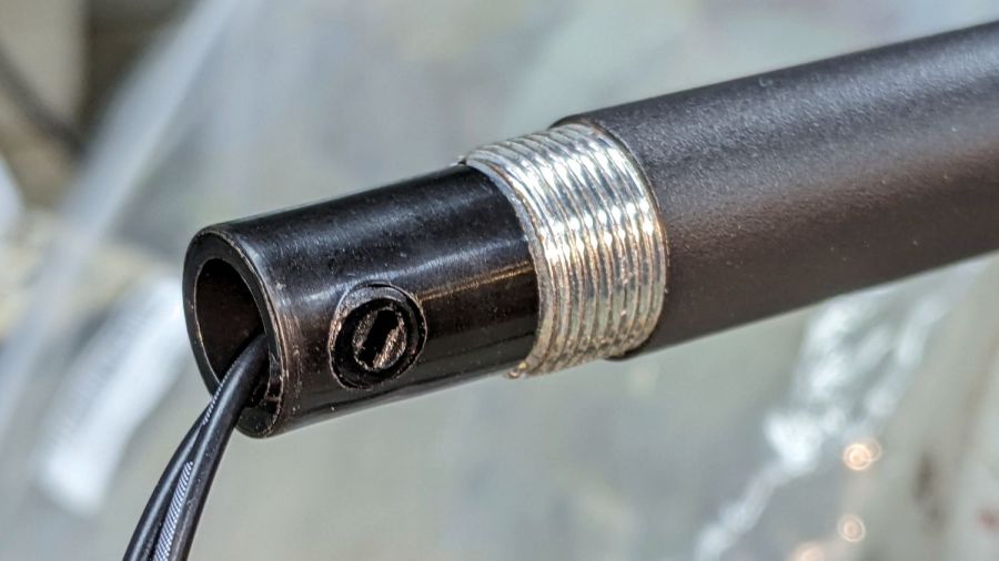
Kinda looks like it grew there and makes one wonder why they don’t include a caddy as a standard option.
The OpenSCAD source code as a GitHub Gist:
| // ShopVac Nozzle Caddy | |
| // Ed Nisley KE4ZNU 2022-02 | |
| Layout = "Show"; // [Handle,Block,Show,Build] | |
| HandleOD = 20.0; | |
| //- Extrusion parameters must match reality! | |
| /* [Hidden] */ | |
| ThreadThick = 0.25; | |
| ThreadWidth = 0.40; | |
| HoleWindage = 0.2; | |
| Protrusion = 0.1; // make holes end cleanly | |
| inch = 25.4; | |
| function IntegerMultiple(Size,Unit) = Unit * ceil(Size / Unit); | |
| ID = 0; | |
| OD = 1; | |
| LENGTH = 2; | |
| //———- | |
| // Dimensions | |
| // Handle lies along X axis | |
| Handle = [200,HandleOD,HandleOD]; // X = longer than anything else | |
| WallThick = 5.0; // Thinnest printed wall | |
| Screw = [4.0,7.0,25.0]; // M4 socket head cap screw | |
| Washer = [4.5,9.0,0.8]; // M4 washer | |
| Insert = [4.0,5.9,10.0]; // M4 brass insert | |
| Block = [15.0,Handle.y + 4*WallThick + 2*Screw[ID],HandleOD + 2*WallThick]; // overall clamp block | |
| echo(str("Block: ",Block)); | |
| Bosses = [[Block.x,9.5,13.0],[Block.x,15.0,9.0]]; | |
| ScrewOC = Handle.y + 2*WallThick + Screw[ID]; | |
| Kerf = 1.0; // cut through middle to apply compression | |
| Gap = 1.25; | |
| CornerRadius = Washer[OD]/2; | |
| //———————- | |
| // Useful routines | |
| module PolyCyl(Dia,Height,ForceSides=0) { // based on nophead's polyholes | |
| Sides = (ForceSides != 0) ? ForceSides : (ceil(Dia) + 2); | |
| FixDia = Dia / cos(180/Sides); | |
| cylinder(d=(FixDia + HoleWindage),h=Height,$fn=Sides); | |
| } | |
| // Shopvac handle | |
| module Handle() { | |
| rotate([0,90,0]) | |
| translate([0,0,-Handle.x/2]) | |
| rotate(180/(4*8)) | |
| PolyCyl(Handle.y,Handle.x,4*8); | |
| } | |
| // Clamp block | |
| module ClampBlock(BossID=0) { | |
| difference() { | |
| union() { | |
| hull() | |
| for (i=[-1,1], j=[-1,1]) // rounded block | |
| translate([i*(Block.x/2 – CornerRadius),j*(Block.y/2 – CornerRadius),-Block.z/2]) | |
| cylinder(r=CornerRadius,h=Block.z,$fn=8); | |
| translate([0,0,-(Block.z/2 + Bosses[BossID].z/2 – Protrusion)]) | |
| cube(Bosses[BossID],center=true); | |
| } | |
| for (j = [-1,1]) // screw holes | |
| translate([0,j*ScrewOC/2,-(Block.z/2 + Protrusion)]) | |
| rotate(180/6) | |
| PolyCyl(Screw[ID],Block.z + 2*Protrusion,6); | |
| cube([2*Block.x,2*Block.y,Kerf],center=true); | |
| Handle(); | |
| translate([0,0,-Block.z]) | |
| rotate(180/6) | |
| PolyCyl(Screw[ID],Block.z,6); | |
| translate([0,0,-(Handle.z/2 + Insert[LENGTH])]) | |
| rotate(180/6) | |
| PolyCyl(Insert[OD],Handle.y,6); | |
| } | |
| } | |
| // Splice block less handle bore | |
| module ShapedBlock() { | |
| difference() { | |
| ClampBlock(); | |
| Handle(); | |
| } | |
| } | |
| //———- | |
| // Build them | |
| if (Layout == "Handle") | |
| Handle(); | |
| if (Layout == "Block") | |
| ClampBlock(BossID=0); | |
| if (Layout == "Show") { | |
| color("Green",0.25) | |
| Handle(); | |
| xofs = -((len(Bosses) – 1)/2 * Gap*Block.x); | |
| for (i=[0:len(Bosses) – 1]) | |
| translate([xofs + i*Gap*Block.x,0,0]) | |
| ClampBlock(i); | |
| } | |
| if (Layout == "Build") { | |
| yofs = -((len(Bosses) – 1)/2 * Gap*Block.y); | |
| for (j=[0:len(Bosses) – 1]) | |
| translate([0,yofs + j*Gap*Block.y,0]) | |
| translate([0,0,Block.x/2]) | |
| rotate([0,90,0]) | |
| ClampBlock(j); | |
| } |