Ed Nisley's Blog: Shop notes, electronics, firmware, machinery, 3D printing, laser cuttery, and curiosities. Contents: 100% human thinking, 0% AI slop.
Tag: Improvements
Making the world a better place, one piece at a time
My desire to not form deep emotional bonds with a fixture
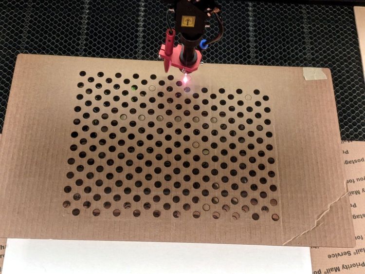
To get a cardboard spike plate:
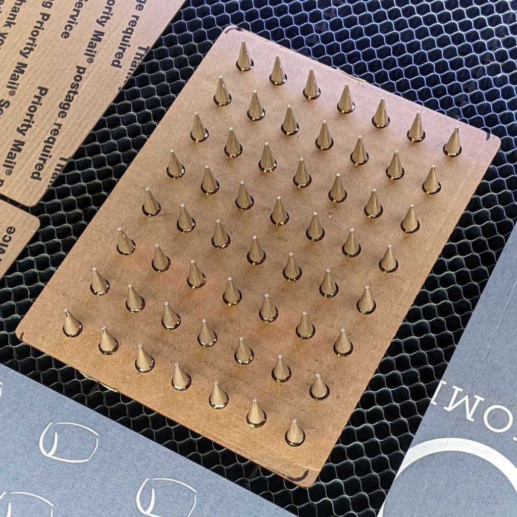
Laser spike plate – pristine
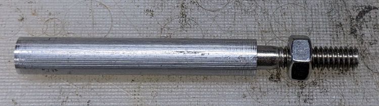
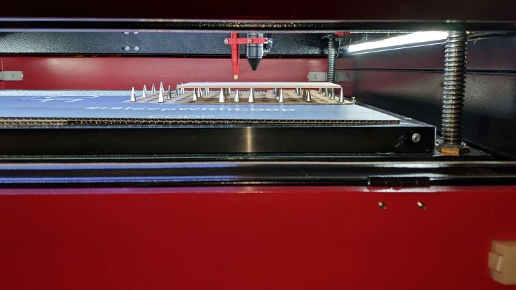
The punk spikes stick to a layer of ordinary masking tape across the back surface which lets them sit flat on the honeycomb and support a sheet parallel to the platform. They’re nominally an inch tall, which works out to a very consistent 24 mm, and come with a matching set of 6 mm M3×0.5 truss-head screws now residing in a ziplock bag against future need.
The spike plate works well under thin paper-like sheets requiring high cutting speed and low power, where the defocused beam just scorches tracks across the cardboard without setting it on fire:
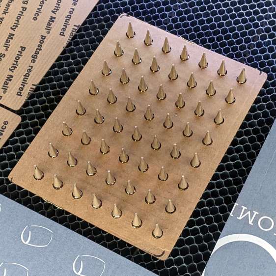
Laser spike plate – scarred surface
Nota bene: a cardboard sheet makes a terrible backing plate under material requiring slow speed and high power, like MDF / plywood / acrylic, where the cloud of combustible gases under the victim forms a very effective flamethrower. You have been warned.
Obviously, you need not fill every hole. Leaving some holes vacant doesn’t (seem to ) allow much smoke removal downward through the honeycomb, perhaps because there’s insufficient perimeter area to get enough wind into the center section.
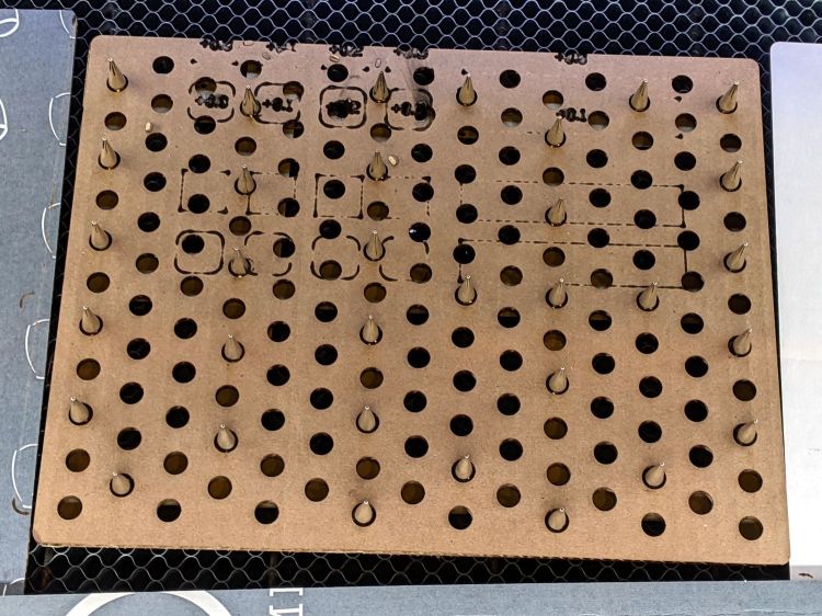
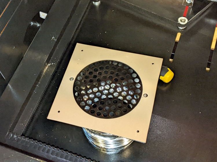
Eventually, the cardboard becomes sufficiently scarred to justify making another one, which is easy enough:
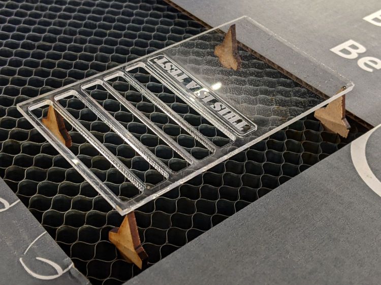
Laser spike plate – hole cutting
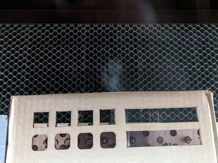
The motivation for raising the target above the platform is to provide good airflow to remove the smoke / fumes / smog from the area, thereby reducing unsightly deposits on the lower surface. Given decent airflow across the platform, this works surprisingly well:
Laser spike plate – smoke plumes
That picture comes through the laser’s tinted polycarbonate window, so it’s somewhat blurred, but shows smoke streamers emerging from the victim’s corrugations and across its surface.
Russ Sadler points out that Chinese CO2 lasers lack air inlets matching their 6 inch = 150 mm outlet port, so fumes accumulate over the workpiece as air leaks in through various panel / hatch gaps and small openings. The simplest solution, at least for my OMTech 60 W laser, seems to be opening the front passthrough hatch:
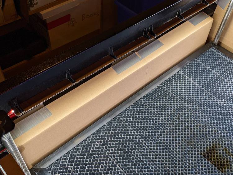
Directing the air flow across the platform from front to rear requires sealing the gaps along the front of the cabinet:
OMTech 60 W laser – front gap seal
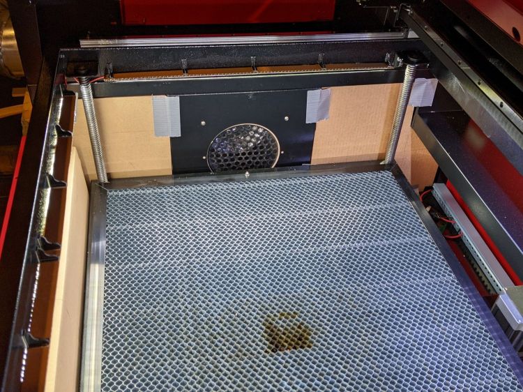
And the huge openings on either side of the exhaust duct:
OMTech 60 W laser – vent box seal
Yes, all those are cardboard sheets and, no, they’re not the final implementation. This is all in the nature of figuring out what works, so being able to cut-to-fit is a Good Idea.
The large gap along the rear edge (on the right, above) for the rear feedthrough opening got a cardboard sheet after engraving some MDF.
Early indications are that it works fine, as witness the smoke streaming off the rear of a cardboard test piece:
Laser spike plate – smoke plumes
Cutting MDF produces copious smoke that fills the cabinet, but it clears quickly and doesn’t escape into the Basement Laboratory if I wait a little longer than I really want to after the cutting stops.
Blocking the unused areas of the honeycomb helps direct airflow in the proper direction:
However, all that upward-directed light goes directly into my glare-sensitive eyeballs, so I added shades above the strips:
COB LED Shade – installed
They’re cut from corrugated cardboard because I have an essentially infinite supply and I’m still working out speeds and intensities. Eventually they’ll become something like black acrylic.
The brackets emerged from the vasty digital deep through the miracle of 3D printing:
COB LED Shade Brackets – slice preview
They’re stuck to the laser cabinet and the cardboard with double-sided duct tape. If you’re careful, they will line up along one edge of the tape, roll over neatly to stick their other face, then a single razor knife cut can separate each pair of neighbors.
The underside sports an aluminized mylar strip to redirect the wasted light in a more useful direction:
COB LED Shade – aluminized Mylar reflector
The tapeless sticky shipped with the laser holds the reflector in place, while its 20 mm width sets the 21 mm shade dimension. Although you want a reasonably smooth layer, it need not be mirror-flat.
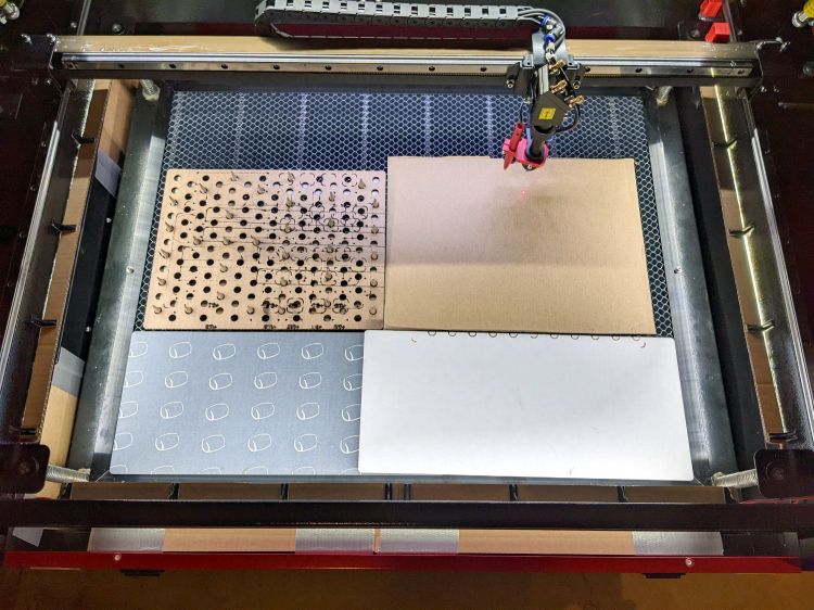
Now it’s really bright in there:
COB LED Shade – overview
While I had my head under the hood, I stuck a fourth strip of COB LEDs on the lip along the rear edge of the opening; it’s bright enough to cast the shadow just forward of the laser head despite the OEM under-gantry LED strip. Because the rear strip is aimed downward, it didn’t need a shade.
The perforated cardboard sheet on the left is a spike plate: more about that later.
This file contains hidden or bidirectional Unicode text that may be interpreted or compiled differently than what appears below. To review, open the file in an editor that reveals hidden Unicode characters.
Learn more about bidirectional Unicode characters
What used to be a “light box” had become a “light pad” powered through a USB Micro-B connector on the side. Unfortunately, the pad’s 5 mm thickness allows for very little mechanical reinforcement around the USB jack, while providing infinite opportunity to apply bending force. Over the course of the last half-dozen years (during which the price has dropped dramatically, despite recent events), the slightest motion flickered the LEDs.
So I squished the jack’s metal shell back into shape, found a short right-angle USB cable, and conjured a reinforcing fixture from the vasty digital deep:
LitUp LED Light Pad
The plate fits under the light pad, where a strip of super-sticky duct tape holds it in place:
LitUp Light Pad USB jack reinforcement – bottom
The USB plug fits between the two blocks with hot-melt glue holding it in place and filling the gap between the plug and the pad.
I’d like to say it’s more elegant than the cable redirection for my tablet, but anything involving black electrical tape and hot-melt glue just isn’t in the running for elegant:
LitUp Light Pad USB jack reinforcement – top
On the other paw, that socket ought to last pretty nearly forever, which counts for a whole lot more around here.
The retina-burn orange tape patches on the connector eliminate all the fumbling inherent to an asymmetric connector with invisible surface features. The USB wall wart on the other end of the cable sports similar markings.
This file contains hidden or bidirectional Unicode text that may be interpreted or compiled differently than what appears below. To review, open the file in an editor that reveals hidden Unicode characters.
Learn more about bidirectional Unicode characters
Nearly everybody with a floor-standing laser cutter eventually decides it’s much too low for comfort:
OMTech Laser – leg risers
Those are the 5 inch sections of a furniture riser set (the 3 inch sections are visible at the left rear of the picture, ready for deployment). With the legs extended to their full length, they put the laser’s honeycomb platform about 30 inches from the floor, so the complete set will raise it to 33-ish inches.
I went full-frontal Archimedes by levering each end of the cabinet up an inch at a time using one of those maple shelves atop an increasingly tall fulcrum made of various planks, then lowering the ever-lengthening legs atop stacks of plywood. Eventually I could roll a floor jack under the end beam to simplify the rest of the lift.
Protip: lock the casters to prevent movement.
More height makes reaching inside the machine much more comfortable!
At least for me. Mary says it’s now much too high for her …
The OMTech laser arrived with a 120 VAC fan blowing air out of the electronics bay on the right side of the cabinet. It runs continuously, because the stepper drivers remain active even when idle, and gave off an annoyingly high-pitched whirrrrr.
The Big Box o’ Fans produced a 24 V tangential blower which (felt like it) moved about the same amount of air with a quieter and lower-pitched hmmmmmm, so I made an adapter to fit it into the original cabinet opening:
OMTech laser – improved electronics fan – mounting
Yeah, it’s hot-melt glued to a stacked pair of laser-cut cardboard plates. Fight me.
The black cardboard makes it rather low-key from the outside:
OMTech laser – improved electronics fan – grille
I reused the original grille, mostly because otherwise I’d have to put it somewhere else.
The anemometer suggests 5 m/s airflow an inch from the grille. Rounding downward from the 25×35 mm opening says it’s pulling 9 CFM from a compartment with a little over a cubic foot of free volume, which sounds enough good to me. For whatever it’s worth, this airflow calculation disagrees with all of the specs and my handwaving calculation in that old blog post.
The cabinet hatch has slits distributing the incoming air over all the active ingredients (somewhat visible inside behind the flash glare):
The OMTech 60 W laser gets its air assist from an aquarium-style air pump in the right rear of the cabinet:
OMTech 60W laser – Z motor – air pump
Since that picture, I’ve sealed the slots for the Z-axis belt tensioner pulleys.
The pump is connected directly to the AC line at the main barrier block (blue and brown on leftmost two terminals):
OMTech 60W laser – AC barrier strip
Even though the pump has very flexy rubber feet, it’s annoyingly noisy and should be off when the laser beam is off.
The knockoff RuiDa KT332N controller (possibly by Ryxon, based on a LightBurn forum thread, but without a visible name anywhere on the hardware or in the manual) has an Aux.Air output terminal:
KT332N Controller – output wiring plug- glued
Yes, the controller is mounted that way inside the electronics bay.
Chipping away the hot-melt glue over the terminals lets you pry the terminal block out of the controller:
KT332N Controller – output wiring plug
The KT332N manual describes the Aux.Air pin 2 function:
Dedicated output. When auxiliary air control is enabled, this port outputs a control signal to control the valve or other relay to release auxiliary air. This port is multiplexed with pen control signal. When auxiliary air control is disabled, this port is assigned as pen control. The output type is open collector. The output can be set to be synchronized with laser or synchronized with work.
Section 4.6 — General and dedicated output
The word “pen” does not occur anywhere else in the manual, so I have no idea what it might mean. Perhaps the controller can also become a pen plotter?
A configuration screen (Menu → Para Setting → Auxi.Air) gives the options:
KT332N Controller – Air Assist Config screen
Section 9.2 of the manual describes the choices, although not quite in the same words:
Blowing method:The way of the air is blown during processing. Can be configured to output fire, process gas, and manual gas.
Blow on delay:Delay time after turning on air blowing
Blow off delay:Delay time before turning off the blow
Section 7.2 gives the electrical parameters:
All output signals of this controller are output based on opto-coupler isolation technology and OC gate output. Its maximum driving capacity is 300mA, which can directly drive 6V / 24V relays, light-emitting indicators, buzzer alarm devices, etc.
Section 7.2 — Output
I wired an AC solid state relay (surely a counterfeit Fotek) in series with the pump’s AC Line wire:
KT332N Controller – Air Assist SSR installed
It’s firmly stuck to the bottom of the electronics bay with heatsink tape, not that it gets particularly warm switching a few dozen watts of pump.
Because the output pin is active low, the SSR + input comes from a ferrule jammed into the 24 V supply pin on the controller, along with the original ferrule holding three other wires:
KT332N Controller – Air Assist SSR wiring
With all that in place, I turned it on and … the air pump did not turn on when I ran the next job. I could manually turn the pump on with the front panel Aux Air button, but it shut off as soon as I ran a file.
The “enable” setting referred to in Section 4.6 appears in the Vendor Parameters:
Enable the auxiliary air control : If you want to use the Wind signal of the output port to control the fan switch in layers, you must enable this parameter. Otherwise, the Wind signal outputs other signals.
Section 9.1 — Vendor Parameters
The Vendor Settings are protected by a password I don’t know do not appear in the section of settings I assumed they would be in, based on the manual’s wording. It seems an external program connected to the controller by USB or the network provides the only way to access these settings.
Fortunately, LightBurn exposes the Vendor settings after you click through a warning dialog:
LightBurn Vendor Config – Air Assist Enable
And then It Just Works™.
The “Blow when laser” option turns on the pump whenever the laser power supply is producing a beam, so it switches on and off at a furious pace. This is not the option you are looking for.