Ed Nisley's Blog: Shop notes, electronics, firmware, machinery, 3D printing, laser cuttery, and curiosities. Contents: 100% human thinking, 0% AI slop.
Tag: Improvements
Making the world a better place, one piece at a time
After tweaking the OMTech laser’s axis scale calibration, it seemed like a good idea to see whether the axes run perpendicular to each other:
OMTech Axis Cal – framing square
A carpenter’s framing square isn’t the most precise instrument, but the pair in my collection agree on their right-angularity to within my ability to measure the difference.
Aligning the short arm with the Y axis showed the X axis was off by 1.2 mm in 21 inches = 530 mm, an angle of 0.13°, which is just about as good as it’s ever going to be.
The honeycomb frame is definitely not a precisely aligned unit, but the front edge is parallel to the X axis within an astonishing 0.03°, measured along the rear edge of the long arm pushed against the front of the frame. The aluminum frame has a distinct outward bow in the middle averaged out by the long arm.
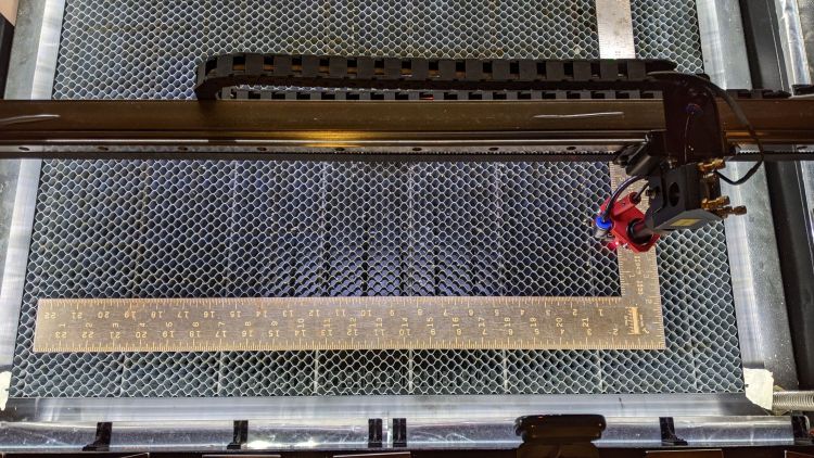
Unfortunately, the honeycomb frame on the right side is nowhere near that nice. While I had the long scale aligned with the X axis travel, I sleazed a smaller square up against it:
OMTech Axis Cal – honeycomb frame misalignment
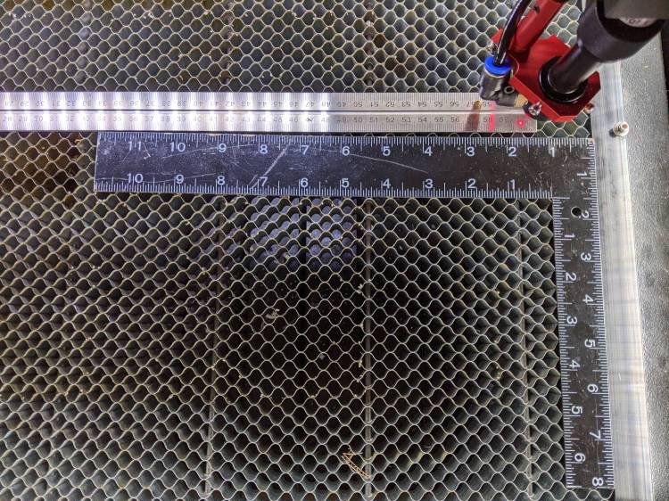
It’s as bad as it looks:
OMTech Axis Cal – honeycomb frame vs axis travel – detail
The scale departs from the black square’s arm by 4 mm over 260 mm, for a 0.88° misalignment.
I think the honeycomb frame is, at best, a parallelogram (and likely a trapezoid), and each side is also bowed by a few millimeters along its length, so any misalignment will depend on where you stand and which way you look.
In all fairness, it was never intended as an alignment fixture and nobody really cares about angular misalignment as long as the puppy portrait comes out pretty much in the middle of the coaster.
Angular Alignment meme
Yes, yes I am.
It’s easy enough to make an alignment fixture:
OMTech Axis Cal – honeycomb frame angle fixture
The cut along the left edge is, by definition, parallel to the Y axis, so the left edge of the larger slice serves to align flat things to be cut and hold them in place:
Laser cutter deck fixture
The upper sheet (a simple chipboard rectangle) sits perpendicular (set with the short square) to the edge, held to the honeycomb with magnets, and kept in alignment with two adjustable stops snugged against it. A few smaller magnets can hold the sheet flat against the honeycomb as needed.
The sliver cut off the MDF is 7.85 mm at the top and 9.70 mm at the bottom, for an angle of 0.53° over its 210 mm length, a bit less than the angle measured above. It now lives in the tooling pile against future need.
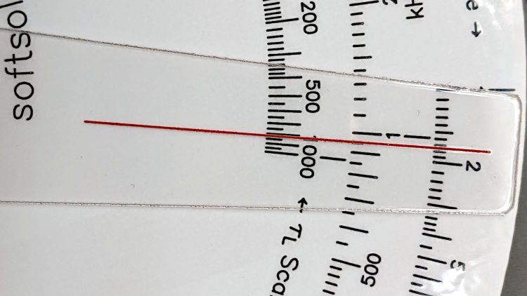
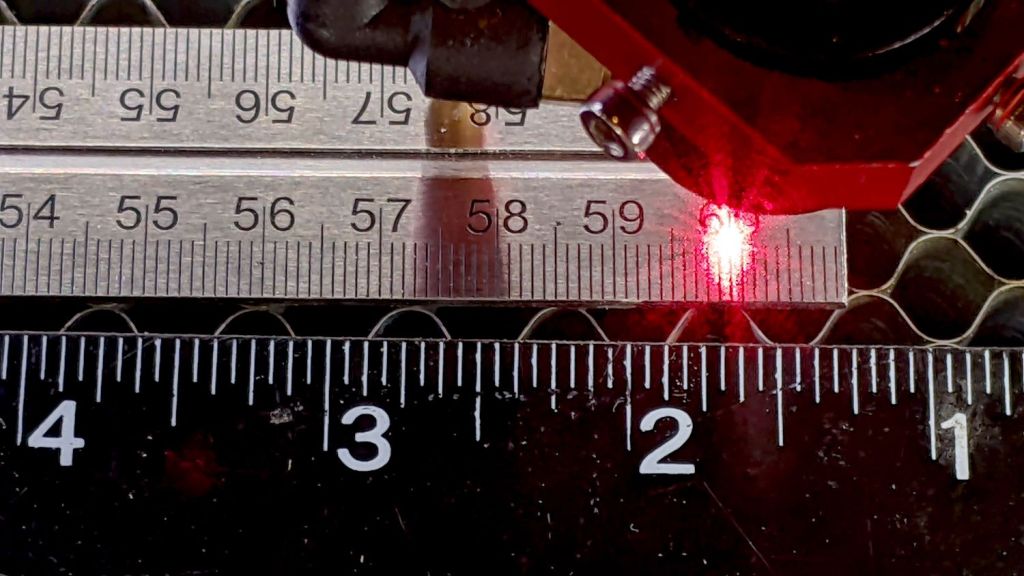
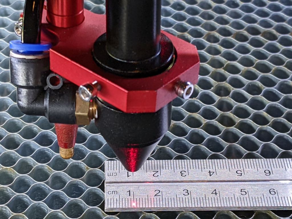
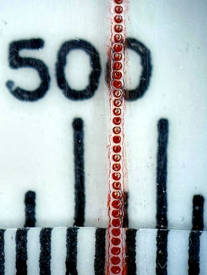
Laying out my longest engraved scale on the honeycomb:
OMTech Axis Cal – dot positioning
The zero-th step aligns the scale with the axis travel: slide one end of the scale to put the dot on the edge, jog to the other end, slide to put the dot on the edge, iterate until the dot is the same brightness on both ends.
The scale lines are a tidy 0.2 mm wide, the red laser dot might be 0.4 (it’s rectangular-ish), and a jog increment of 0.2 mm works well. I can manually align (pronounced “slide”) the scale on the honeycomb to center the dot within a line, whereupon moving the head a known distance to the other end of the scale and counting-while-jogging a few steps until the dot drops into the proper line gives the offset from the correct distance.
Jogging 590 mm along the X axis produced 589.8 mm of actual travel (one jog step short of the line 590 mm from the start), an error of -340 ppm.
Jogging 495 mm along the Y axis travels 494.4 mm, an error of 1212 ppm. That’s considerably more than I expected and required a few iterations until I believed it.
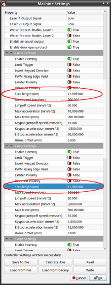
Both axes use steppers with 20 tooth pulleys and 3 mm pitch belts, so the laser head moves 60 mm per motor revolution. The stepper drivers are configured for 5000 steps/rev, so the axes should have a step length of 12 µm = 60 mm / 5000 step. Both axes arrived with Step Length values set to weird numbers very close to 12 µm, but, after a quick check showed incorrect travel distances, I reset them to 12 µm before making real measurements.
LightBurn provides access to the Ruida controller’s “Vendor Settings” (after a warning to not mess things up) and allows you to change them:
OMTech Laser – Axis step length settings
The values shown above come from multiplying 12 µm by the ratio of the actual to the intended distance:
11.9959 = 12 × 589.8 / 590
11.9855 = 12 × 494.4 / 495
Repeating the tests with those slightly smaller step sizes produces motions that are spot on to within my ability to measure them.
Neither of those changes was large enough to affect the outcome of cutting the Tek Circuit Computer decks, which are much smaller than the full extent of the axes and thus see much smaller errors.
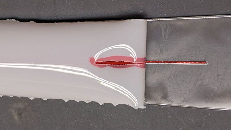
Entirely by accident, I discovered that engraving a hairline with LightBurn’s Dot Mode using 1 ms burns and 0.1 mm spacing produces a continuous trench, rather than the series of dots at 0.25 mm:
Tek CC – Cursor Hairline – 30pct 100u – oblique view
The left is at 20% power (12-ish W) and the right is at 30% (18-ish W), both filled with Pro Sharpie red ink.
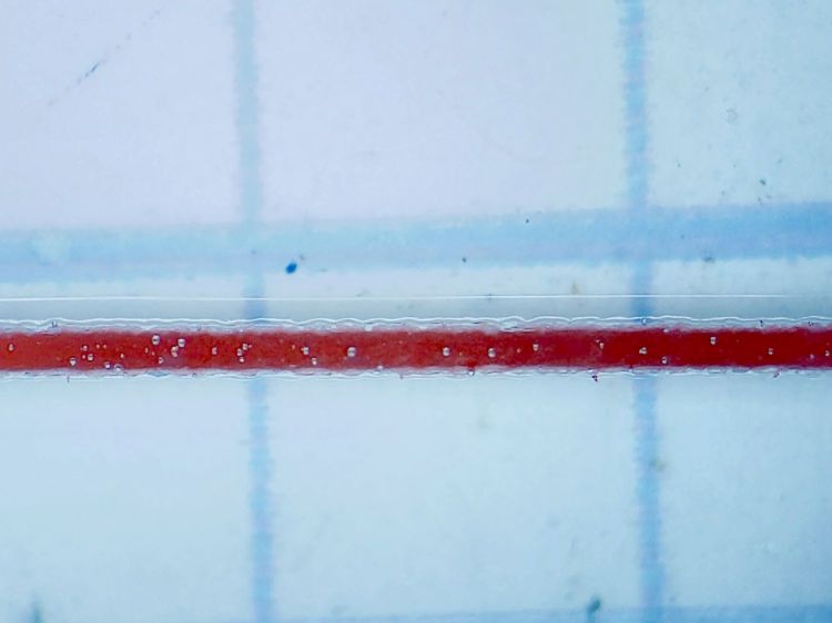
The V-shaped groove is even more obvious when seen end-on:
Tek CC – Cursor Hairline – 30pct 100u – end view
In both cases, the travel speed seems to be about 10 mm/s regardless of the speed set in the cut layer parameters. The higher power level produces a slightly wider cut that doesn’t seem deeper, which I cannot explain.
Filled with red lacquer crayon, the hairline looks absolutely gorgeous:
Tek CC – Cursor Hairline – 30pct 100u – in place
Engraving the PETG sheet with the protective film in place produces a neat cut with the film edges fused to the plastic.
Cutting the outline and pivot hole in the same operation ensures everything remains perfectly aligned:
Tek CC – Cursor Laser Cutting
Scribble red crayon over the film, make sure the trench is completely filled, peel the film off with some attention to not smearing the pigment, and it’s about as good a hairline as you (well, I) could ask for:
Tek CC – Cursor Hairline – 30pct 100u – Width
The pigment in the trench is about 0.2 mm wide, with slight heat distortion along each side, and I’ll call it Plenty Good Enough.
Totally did not expect this!
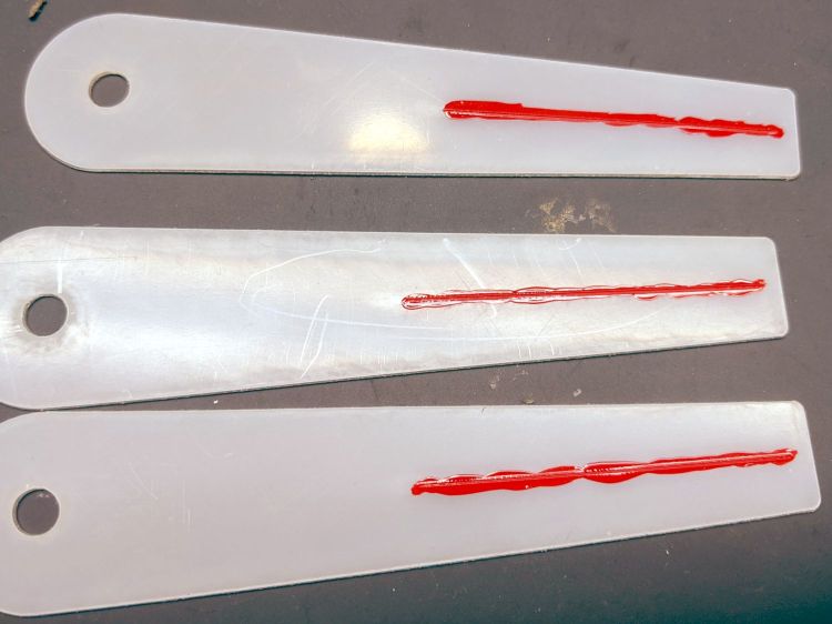
Getting a good-looking hairline on a good-looking cursor turns out to be a major challenge, because there’s nowhere to hide the blunders. A few of the many dead ends along the way shows what’s involved:
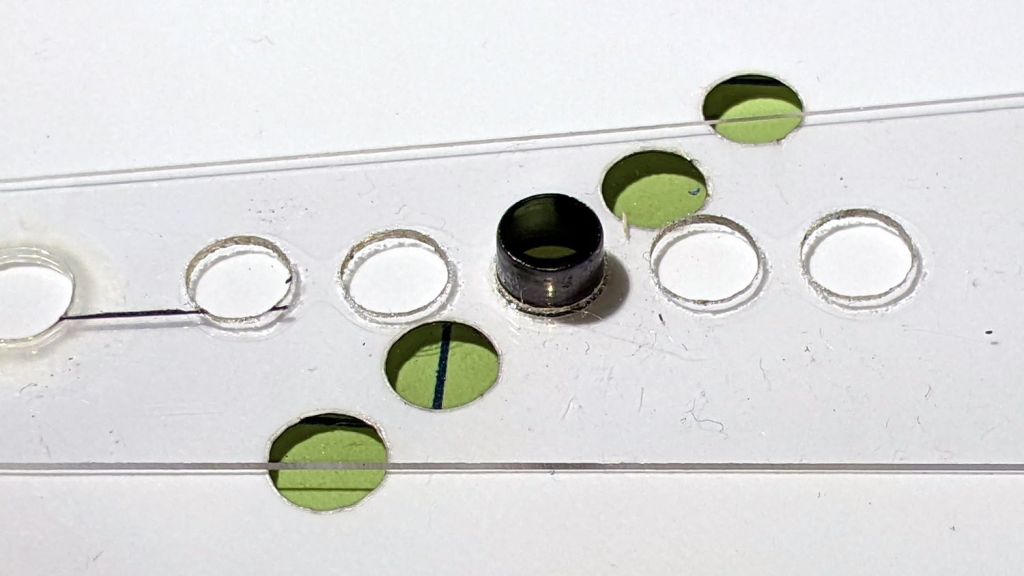
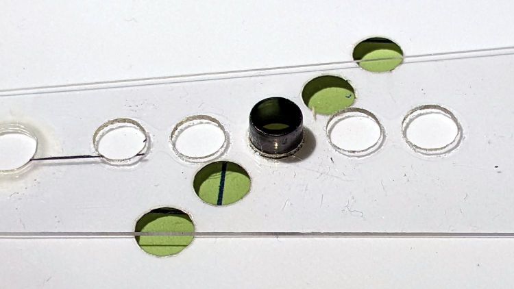
The nominal 5.5 mm OD of the eyelet turns out to be 5.45 mm and fits neatly into a nominal 5.3 mm hole laser-cut into either PETG or laminated paper:
Laser cutter – hole size test
The holes are 5.1 mm on one end and increase by 0.1 mm.
The eyelet fits loosely into the 5.4 mm hole, snugly into 5.3 mm, and only into the 5.2 mm paper hole.
So the nominal 5.3 mm hole is really 5.45 mm, which means the beam adds 0.15 mm to the hole diameter, about 0.08 mm to each side.
Given that the eyelet isn’t quite round and the holes aren’t exactly glass-smooth, figuring a 0.2 mm kerf seems both reasonable and easier to remember.
Obviously, the results will differ depending on what’s being cut, how thick it is, and probably the phase of the moon.
This is the season for erecting the structures upon which the pole beans will climb:
Garden Bean Poles – overview
They’re made from a dozen small trees and branches of larger trees harvested around the yard. They last for a few years, just long enough for the next crop to reach useful lengths.
We lash them together with fabric strips:
Garden Bean Poles – joint detail
My knot hand is weak, but seems sufficient to the task.
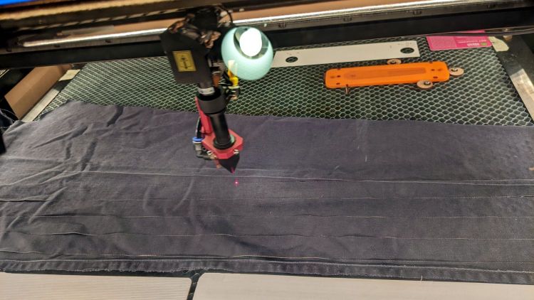
Mary formerly tore the strips from old jeans / pants / whatever, which required considerable effort, produced ragged edges, and filled the air with fabric dust. This year, I proposed an alternative:
Garden Bean Poles – laser cutting ties
The weird thing in the middle is a reflection of an overhead can light in the laser cabinet’s polycarb lid.
From starting the LightBurn layout to presenting the strips for final inspection required the better part of ten minutes. I scissors-cut along the main seams to get single fabric layers, with everything above the crotch seam wadded off the platform to the left.
As with my shop raglets, the layout depends on LightBurn’s overhead camera view to align the cuts with the fabric on the platform:
Bean Pole Ties – LightBurn layout
It’d be easier to see with lighter fabric, but that’s what came to hand in the scrap box and the beans won’t care. We do not anticipate complaints about the odor of charred fabric when they reach the top of the poles, either.
The strips must align with the fabric’s grain to put the warp threads along their length, which makes the main side seam parallel to the X-axis. Even I can handle that layout!
Yes, the strips have rounded corners and, no, it doesn’t matter.
Not knowing what to expect, I peeled the protective plastic off the styrene PETG sheet before cutting the perimeter, thereby dooming myself to about five minutes of polishing with Novus 2 to remove the condensed vaopor and another five minutes restoring the shine with Novus 1. Next time, I’ll know better.
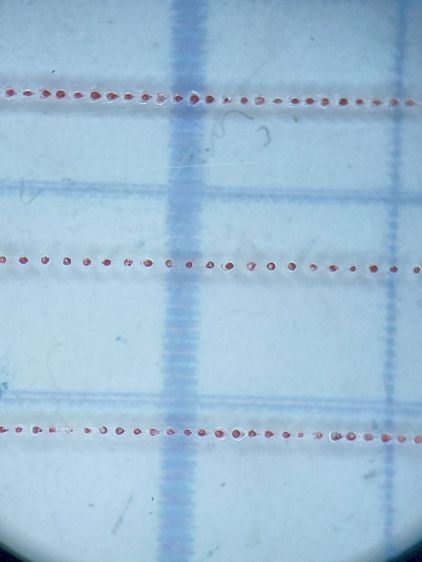
Eyeballometrically, the hairline is a lovely fine line, but it’s really a series of craters on 0.25 mm centers filled with red Pro Sharpie marker and wiped off with denatured alcohol:
Tek CC – laser-etched cursor hairline – detail
That’s dot mode: 2 ms pulses at 20% power (about 12 W) with a line speed of 100 mm/s and 0.25 mm dot spacing. The craters look to be 0.15 mm in diameter, with a 0.15 mm blast radius merging into a line along the sides. The view is looking through the undamaged side of the cursor, so you’re seeing the craters from their tips.
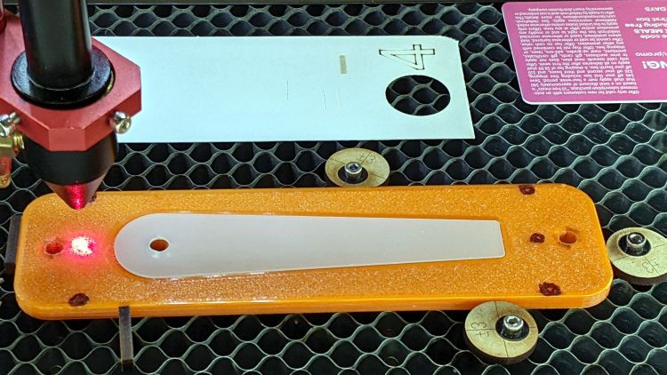
I cut the cursor and engraved / etched the hairline in one operation, by just laying a rectangle on the honeycomb and having my way with it:
The six pips (small printed holes with ugly black outlines) intended for the Sherline’s laser aligner make this feasible, although the accuracy of the OMTech’s laser pointer requires precisely setting the focal point atop the fixture.
The corners of LightBurn’s tooling layer (the enclosing rectangle) match the corner pip positions, so framing the pattern should light up those four holes. Putting the Job Origin (small green square) at the center-left point lets me tweak the machine’s origin to drop the alignment laser into that pip.
AFAICT, burning a cute puppy picture pretty close to the middle of a slate coaster makes everybody else deliriously happy.
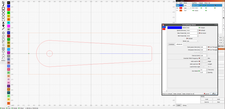
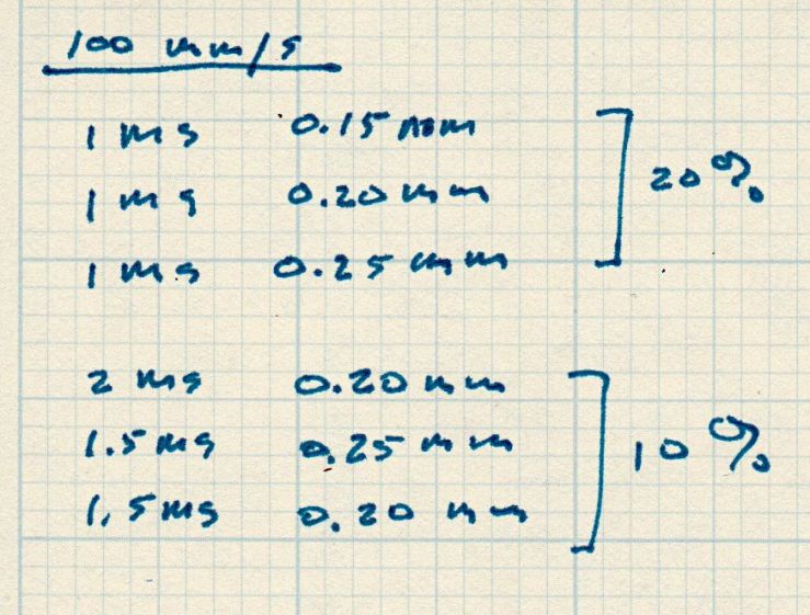
Setting up the cut layer parameters:
Tek CC Cursor – laser dot mode tests
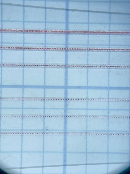
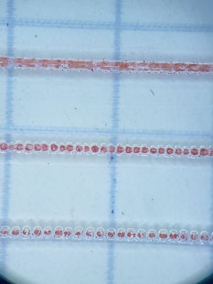
Burning through the protective film, peeling it off, filling with Sharpie, and wiping with alcohol produces interesting results against a 0.1 inch = 2.54 mm grid:
Tek CC Cursor – dot mode 1-2ms 10-20pct
The angled top and bottom lines are the edges of the cursor, positioned with the craters on the top surface.
The bottom three lines at 10% power consist of distinct 0.10 mm craters incapable of holding much ink:
Tek CC Cursor – dot mode 2ms 10pct
The top three lines at 20% power have 0.15 mm craters and look better:
Tek CC Cursor – dot mode 1ms 20pct
The top line was a complete surprise: it seems a 20% duty cycle does not turn off completely between 1 ms dots spaced at 0.15 mm. I expected a row of slightly overlapping dots, which is obviously not what happens.
Punching the dots through the protective film eliminated the polishing operation, although I have yet to cut the perimeter with the film in place.
More experimentation is in order, but it looks like I can finally engrave good-looking and perfectly aligned hairlines on nicely cut cursors without all those tedious manual machining operations.