Ed Nisley's Blog: Shop notes, electronics, firmware, machinery, 3D printing, laser cuttery, and curiosities. Contents: 100% human thinking, 0% AI slop.
Tag: Improvements
Making the world a better place, one piece at a time
Quick summary: the current Linux startup machinery Runs All The Things! in parallel, leaving you to figure out all the interdependencies and update all the script files to match your requirements. Mostly, the distro maintainers figure all that, but if you have essential files mounted as NFS shares, then you can will reach a login screen before the mount process completes.
Having wrestled with this problem for a while, I think I’ve doped out the right way to coerce the Upstart Pachinko Machine to converge on a workable login.
The solution is to fire off a unique signal after the NFS mount command, then force the display manager to wait until it receives that signal, rather than depend on happenstance as I did before. The mounts occur in /etc/init/local.conf, which now looks like this:
description "Stuff that should be in /etc/rc.local"
author "Ed Nisley - KE4ZNU"

start on (local-filesystems and net-device-up IFACE=em1)
stop on shutdown

emits nfs-mounted

script

logger Starting local init...

logger Mounting NFS filesystems
mount /mnt/bulkdata
mount /mnt/userfiles
mount /mnt/diskimages
mount /mnt/music
initctl emit nfs-mounted
logger Ending local init

end script
The start condition ensures that this code won’t run until the wired LAN is up; note that what was once eth0 is now em1. Then, after the mounts happen, initctl fires the nfs-mounted signal.
The modification to /etc/init/lightdm.conf script consists of one additional line to wait for that signal:
start on ((filesystem
           and runlevel [!06]
           and started dbus
           and plymouth-ready
           and nfs-mounted)
          or runlevel PREVLEVEL=S)

stop on runlevel [016]

emits login-session-start
emits desktop-session-start
emits desktop-shutdown
I’m not convinced lightdm.conf is the right spot to jam a stick in the gears, but it seems to be the least-awful alternative. The login-session-start signal doesn’t appear in any file in that subdirectory and I have no idea where else to look.
Anyhow, the greeter screen now shows a desktop background from the NFS mount, which I regard as A Good Sign:
A Home Shop Machinist article (A Speed Key for Your Four-Jaw Chuck, p 67 Nov-Dec 2013, David Morrow) showed some lovely knurled steel knobs. These 3D printed knobs aren’t nearly as pretty, but they do much the same thing:
Sherline Knobs – in 4 jaw chuck
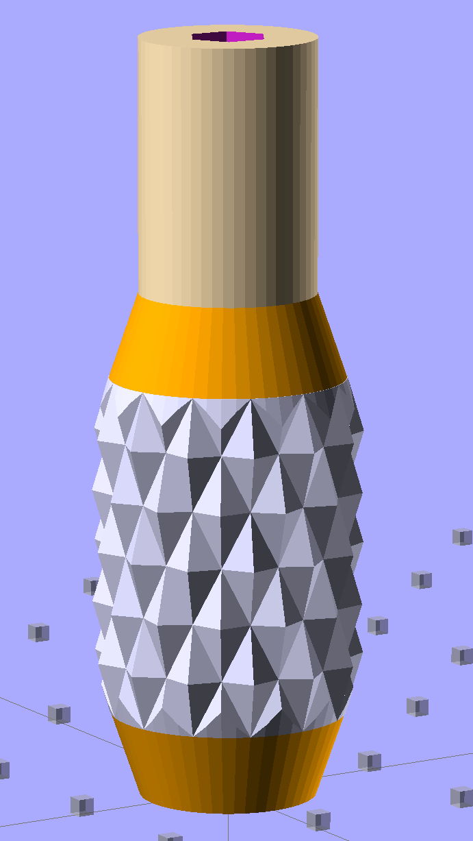
The solid model resembles the illegitimate offspring of a wine bottle and a pineapple:
Sherline Knob – solid model
The knurling comes from aubenc’s Knurled Surface Library v2. I ran off a prototype (on the left), then tweaked the dimensions to get the final version on the right:
Sherline Knobs – knurl depth variation
Being that type of guy, I define the knurl in terms of its diametral pitch, compute the diamond width & length to fit in the available space, then hand those measurements to the knurling library… which recomputes everything and decides on one less diamond than I do: NumSides has a Finagle Constant of -1 to make the answer come out right. We may be using a different diameter or something, but I haven’t deciphered the source code. It’s parametric out the wazoo, as usual, so you can spin up what you like, how you like it.
Anyhow, a 24 DP knurl with 1.0 mm depth looks and feels pretty good; the XY resolution isn’t good enough for a 48 DP knurl around that knob diameter. The diamonds don’t come out as crisp and pointy as crushed steel knurls, but they’re OK for my fingers.
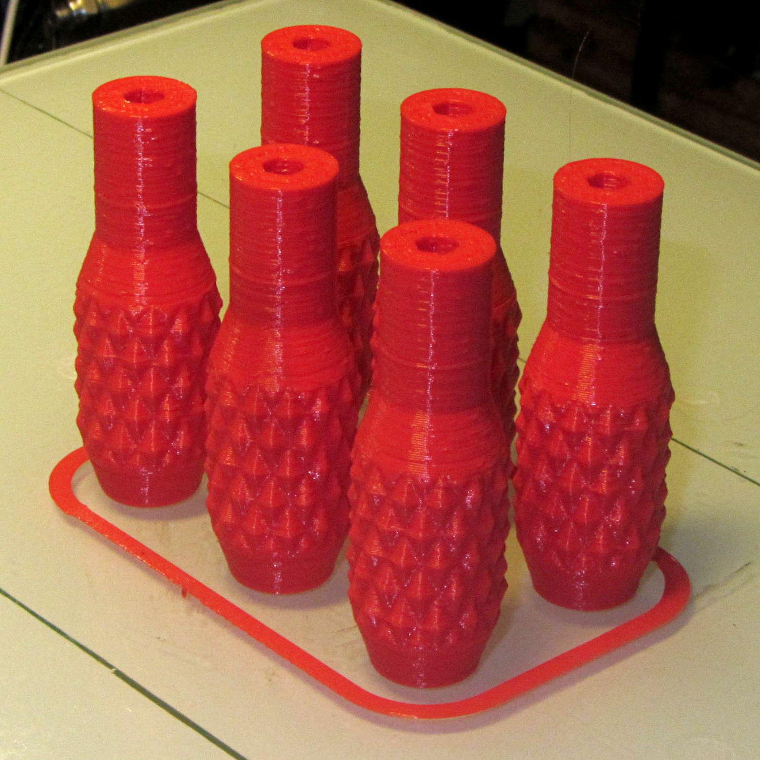
Doing half a dozen doesn’t take much longer than doing a few, because there’s a 20 second minimum layer time in effect and those things don’t have much plastic, so now I have one for the hold-down clamps and another for Show-n-Tell sessions:
Sherline Knobs – M2 platform
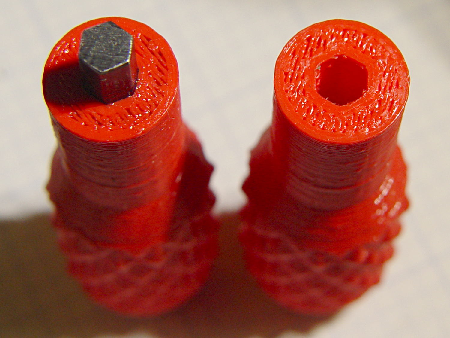
I chopped a 5/32 inch hex key into five 15 mm lengths with a Dremel cutoff wheel, then filed both ends flat and broke the edges. The hex stubs were a press fit in the hex holes, so I finger-started them, grabbed the hex in the drill press, aligned the handle below, and rammed the stub about 5 mm deep. The final depth comes from jamming the wrench into the chuck and pressing firmly, so the stubs project exactly as far as possible:
Sherline Knobs – hex key inserted
One might quibble about the infill on the end; one may go adjust one’s own printer as one prefers.
There’s 0.1 mm more HoleWindage than usual, because these holes must fix a hex shaft, not a circular pin, and the corners need some clearance. They came out a firm press fit: exactly what’s needed.
They’re no good for final tightening of those chuck jaws, but that’s not their purpose…
Those simple floor brush strips for the Samsung vacuum cleaner worked moderately well, but the urethane adhesive didn’t have enough grip on the plastic strips. Having just run out of that batch, I made up another set with slightly undercut holes:
Bushing Solid Model – better holes – bottom
That’s half a thread width on each side, just enough to give the adhesive something to grab. Such is the plan, anyway.
I taped the strips to a pair of credit cards (actually, flat cards without embossed characters), slathered a thin layer of urethane atop them, and laid on squares of the same wool fabric I used the last time:
Samsung vacuum floor strips – gluing
Then I piled a steel block atop an aluminum slab on both arrays, fast forwarded a day, peeled and flexed and cut the strips apart:
Samsung floor brushes – glued
The urethane foamed through the holes as I hoped and (seems to have) locked the fabric in place, at least well enough to withstand some experimental bending on the workbench.
Now, to see how they stand up to actual use…
The OpenSCAD source code:
// Samsung Vacuum cleaner nozzle floor strips
// Ed Nisley KE4ZNU January 2013
//  November 2013 - adapt to M2, enlarge holes

Layout = "Build";			// Show, Build

//- Extrusion parameters must match reality!
//  Print with +0 shells and 3 solid layers

ThreadThick = 0.25;
ThreadWidth = 0.4;

HoleWindage = 0.75;

function IntegerMultiple(Size,Unit) = Unit * ceil(Size / Unit);

Protrusion = 0.1;           // make holes end cleanly

//----------------------
// Dimensions

Body = [6.0,59.0,3*ThreadThick];	// width, length, thick

Tab1 = [4.5,5.0,0.0];				// width, length, offset from centerline
Tab2 = [3.5,5.0,0.5];

HoleOC = 8.0;						// adhesive anchoring holes
HoleDia = 2.0;
HoleSides = 4;
HoleMax = floor(Body[1]/(2*HoleOC));

echo("HoleMax: ",HoleMax);

//----------------------
// Useful routines

module PolyCyl(Dia,Height,ForceSides=0) {           // based on nophead's polyholes

Sides = (ForceSides != 0) ? ForceSides : (ceil(Dia) + 2);

FixDia = Dia / cos(180/Sides);

cylinder(r=(FixDia + HoleWindage)/2,
         h=Height,
         $fn=Sides);
}

module ShowPegGrid(Space = 10.0,Size = 1.0) {

    Range = floor(50 / Space);

    for (x=[-Range:Range])
        for (y=[-Range:Range])
            translate([x*Space,y*Space,Size/2])
            %cube(Size,center=true);

}

module BackingStrip() {

	difference() {
		union() {
			translate([0,0,Body[2]/2])
			cube(Body,center=true);
			translate([Tab1[2],-1*Body[1]/2,Body[2]/2])
			cube([Tab1[0],2*Tab1[1],Body[2]],center=true);
			translate([Tab2[2],+1*Body[1]/2,Body[2]/2])
			cube([Tab2[0],2*Tab2[1],Body[2]],center=true);
		}
		for (i = [-HoleMax:HoleMax])
			translate([0,i*HoleOC,-Protrusion])
			rotate(45) {
				PolyCyl(HoleDia,(Body[2] + 2*Protrusion),HoleSides);
				PolyCyl((HoleDia + ThreadWidth),(ThreadThick + Protrusion),HoleSides);
			}
	}
}

//----------------------
// Build it!

ShowPegGrid();

if (Layout == "Show")
	BackingStrip();

if (Layout == "Build")
	rotate(90) BackingStrip();
While reducing the clutter atop the Electronics Workbench, I ran off four more probe flange reinforcements, just so I’m ready for the next crunch:
HP scope probe flange disks
They’re almost identical to the previous version, although I tweaked the taper to end slightly inside the cylindrical cup, thereby eliminating the coincident faces and leaving a minute rim that doesn’t matter:
HP Scope Probe Flange Repair – bottom
Given that I’ve had the ‘scope for nigh onto two decades and have only broken one probe flange, I think four reinforcements will be a lifetime supply: with any luck, the scope will blow a capacitor before I do.
The OpenSCAD source code:
// Tek Scope Probe Flange
// Ed Nisley KE4ZNU November 2013

//- Extrusion parameters must match reality!
//  Print with 2 shells and 3 solid layers

ThreadThick = 0.20;
ThreadWidth = 0.40;

HoleWindage = 0.2;

Protrusion = 0.1;            // make holes end cleanly

function IntegerMultiple(Size,Unit) = Unit * ceil(Size / Unit);

//----------------------
// Dimensions

FlangeOD = 16.0;
FlangeID = 8.75;
FlangeThick = IntegerMultiple(1.25,ThreadThick);

DiskOD = FlangeOD + 4*ThreadWidth;
DiskThick = FlangeThick + 4*ThreadThick;

NumSides = 8*4;

//----------------------
// Useful routines

module PolyCyl(Dia,Height,ForceSides=0) {            // based on nophead's polyholes

Sides = (ForceSides != 0) ? ForceSides : (ceil(Dia) + 2);

FixDia = Dia / cos(180/Sides);

cylinder(r=(FixDia + HoleWindage)/2,
h=Height,
$fn=Sides);
}

module ShowPegGrid(Space = 10.0,Size = 1.0) {

Range = floor(50 / Space);

for (x=[-Range:Range])
for (y=[-Range:Range])
translate([x*Space,y*Space,Size/2])
%cube(Size,center=true);

}

//----------------------
// Build it

ShowPegGrid();

difference() {
union() {
translate([0,0,2*ThreadThick])
cylinder(r=DiskOD/2,h=DiskThick,$fn=NumSides);    // cylinder around flange

cylinder(r1=(DiskOD - 2*ThreadWidth)/2,                // flange reinforcing plate
r2=DiskOD/2,
h=(2*ThreadThick + Protrusion),
$fn=NumSides);
}
translate([0,0,(DiskThick - FlangeThick)])                // flange clearance
PolyCyl(FlangeOD,2*FlangeThick,NumSides);

translate([0,0,-DiskThick/2])                            // probe nose clearance
PolyCyl(FlangeID,2*DiskThick,NumSides);
}
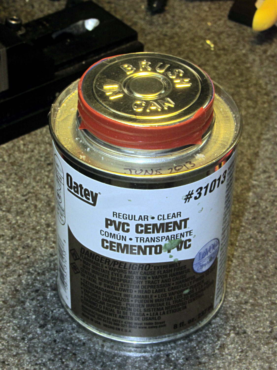
I’ve been doing a lot of fiddly gluing lately and, despite my best efforts, some adhesive collects in the lid’s screw threads. The gummy residue makes it really hard to unscrew the lid without a strap wrench after a few days.
Wrapping two turns of silicone tape around the cap helps tremendously:
The cracker recipe I’m using produces eight sets of crackers, so this time I added a variety of toppings to see what would work out best:
Plain
Salt
Sugar
Cinnamon
Garlic
Chopped chocolate
Chopped cashews
Chopped walnuts
Garlic wins over everything else, hands-down, no contest, but the mixture of all the toppings in the bottom of the cooling bowl was wonderful.
The crackers went into a large pot with a bag of desiccant:
Whole wheat crackers with desiccant
It pulled out 30 grams of water while reducing the humidity to 20% overnight; the crackers started out crisp and became really snappy. Definitely the right way to get the job done.
These vaguely resemble the Processor Crackers recipe in Flatbreads & Flavors (Alford & Duguid):
3 C hard whole wheat flour
1 tsp salt
1 C warm water, more as needed
Toppings
Water sprayer
I’m using coarse-ground red wheat that doesn’t soak up the water like fine-ground flour. The original recipe called for 1-½ C water, which produced a sticky ball.
Blend wheat & salt in food processor
Add water in a slow stream until dough firms up
Blend another minute
Knead half a minute on cutting board
Cover
Let rest 30 minutes while you prepare toppings
Finely chopped toppings work best; the nuts were too coarse.
Preheat oven to 500 °F
Divide dough in eight pieces, cover
For each piece of dough:
Roll to about 2 mm
Put dough on vented pizza pan
Cut cracker shapes with pizza cutter
Sprinkle topping
Spritz with water
Put in oven on top rack
Punch timer for 3 minutes
Prepare next piece
Swap pans
Iterate
Toss the crackers into a big bowl to cool, sampling as needed.
When crackers cool:
Dump into large pot
Add desiccant bag & humidity card
Cover
Snarf combined toppings from bowl
Leave crackers to dry overnight
Wonderful!
Memo to Self: Shredded Parmesan cheese would be pretty good…
As you might expect, changing the layer thickness to 0.1 mm = 100 μm dramatically improves the appearance of the dummy 9 mm Luger bullet on the left, compared to the 0.25 mm = 250 μm layers on the right:
Dummy 9 mm Luger cartridges – 0.1 mm layer – overview
The inside edge of the translucent skirt around the quartet measured 90 to 110 μm, so the layer height is spot on:
Dummy 9 mm Luger bullets – 0.1 mm layer – overhead on platform
That required no adjustments to the M2 at all; It Just Works. Admittedly, that’s with a custom platform and firm supports replacing the springs, plus better Z-axis homing, but the overall structure was fine to start with.
I used the same Slic3r settings as before, with the only change being the layer thickness. Letting it pick the layer width might produce better results, but a 0.35 mm nozzle won’t go much narrower than 0.40 mm anyway.
A closer look at the bullet show the thinner layers provide a better rendition of the stretched sphere forming the nose; it’s less pointy than the one assembled from thicker layers:
Dummy 9 mm Luger bullets – 0.1 mm layer – side
The nose closes better with thinner layers:
Dummy 9 mm Luger bullets – 0.1 mm layer – nose
None of that really matters for this application, but it’s a useful data point.
The downside is that printing with thinner layers requires more time: a single bullet (of 16) requires 2.2 minutes at 250 μm and (of 4) 9 minutes at 100 μm. The simple ratio of layer thicknesses predicts a factor of 2.5, not 4, but the skirt requires a larger fraction of the total time. The estimated time for a 4×4 array at 100 μm comes out at 5.2 minutes each, a factor of 2.4, which is close enough.
Although 100 μm certainly looks better, it doesn’t really improve anything for most of the blocky stuff I make…