The Makergear M2 comes with a plastic block that covers the X-min switch wiring and anchors the end of the filament guide. Because the guide wasn’t anchored to the block, bumping the guide tended to bend the filament where it exited the block. To prevent that, I hot-melt-glued the guide to the block, which really wasn’t particularly elegant. This picture shows the X-min switch relocated to contact the platform, with the slightly out of focus blob anchoring the guide off to the right:

Makergear provides STL files of the M2’s printable bits, including several versions of the wire cover block. This corresponds to the one on my M2, although the rounded edges don’t come through in the plastic very welll:

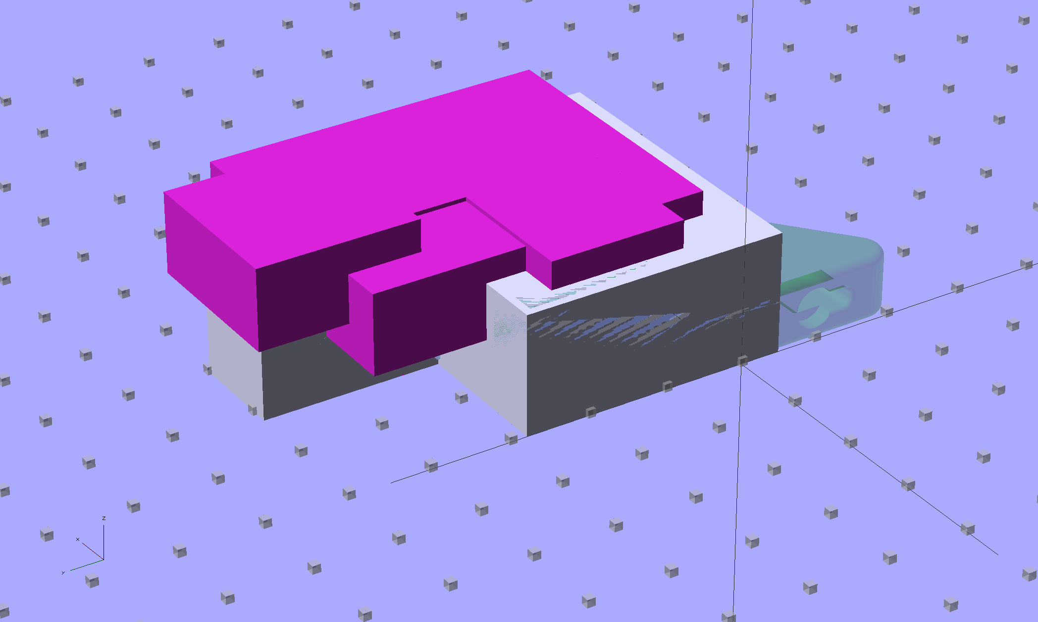
Because STL files aren’t editable, I reverse-engineered the dimensions into an OpenSCAD model that I could use as the basis for a different guide. This is just the basic wire cover, minus the filament guide extension, plus a flat end that wraps around the edge of the chassis:

The trick is to import the STL into OpenSCAD, then build a model that matches the key dimensions. Fortunately, Makergear used hard metric sizes for everything, so most of the numbers came out as integers or single-place decimals:

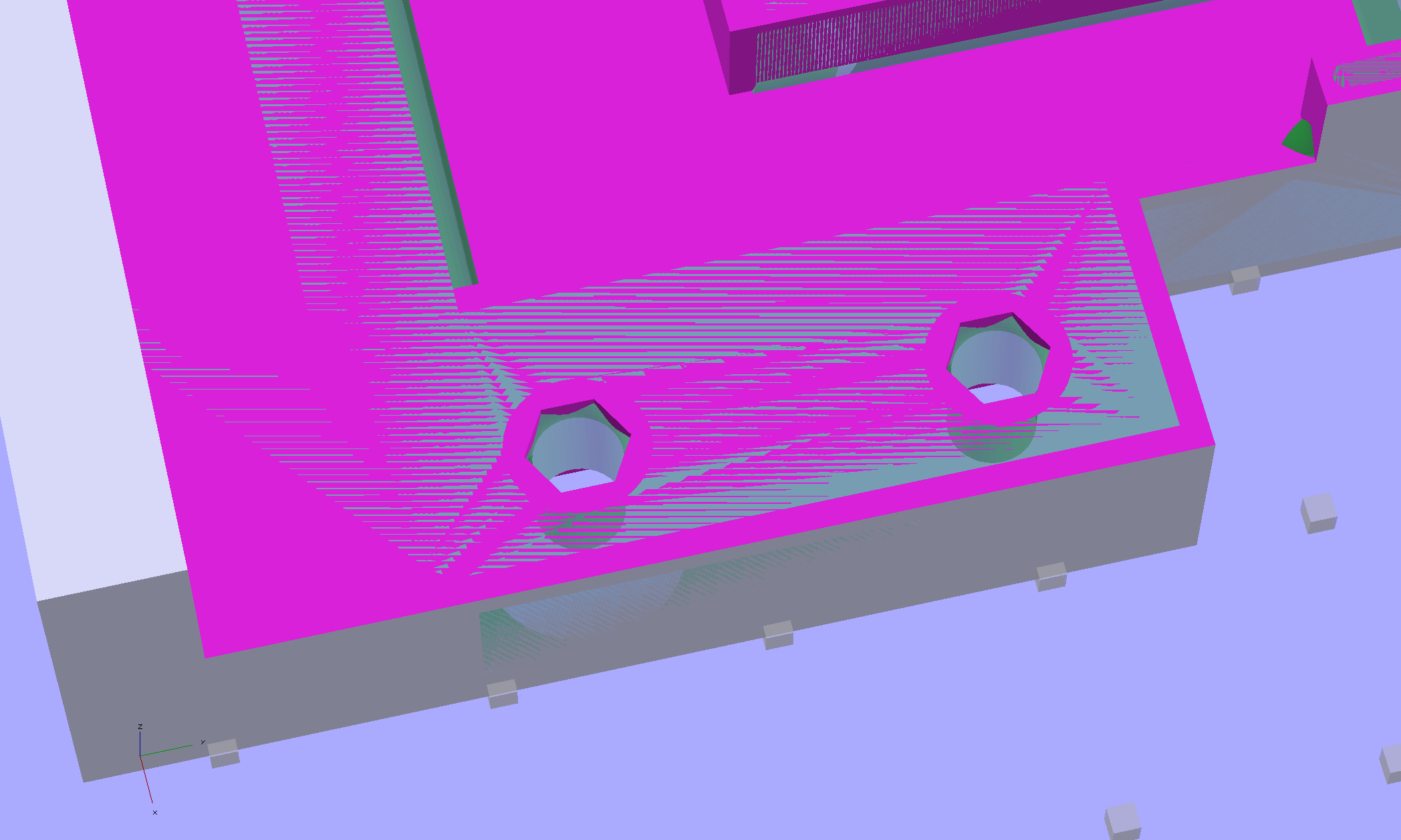
The shimmer indicates coincident surfaces; that’s ordinarily a Very Bad Thing, but in this case it shows that the dimensions match. The top of the holes have neat hexagonal patterns where my straight-sided PolyHoles extend through their chamfered circular holes:
Unlike my from-scratch OpenSCAD models, this one bristles with magic numbers that describe the dimensions of the M2 STL model. The basic shape comes from an extruded polygon matching the outside walls, another extruded polygon knocking out the wire channel, then cubes lopping off the top surfaces:
The end result of all that thrashing around has a certain Soviet Concrete look to it:

This version lacks the filament guide; I wanted to make sure all the protrusions and channels fit, which they sort of did:

The next version will have slightly more clearance on the side and slightly less on the top; that’s easy to do now that I have an editable OpenSCAD model.
The OpenSCAD source code:
// Improved M2 filament guide and X-min switch wire guide
// Ed Nisley KE4ZNU - Oct 2013

function IntegerMultiple(Size,Unit) = Unit * ceil(Size / Unit);

Protrusion = 0.1;

HoleWindage = 0.2;

//- Sizes

PlateMinThick = 8.0;				// basic thickness excluding wire guides
PlateLength = 5.0;					// from side of frame beyond top wire guide

TopGuideLength = 7.0;				// protrusion from plate

PlateThick = PlateMinThick + TopGuideLength;

echo(str("Total thickness: ",PlateThick));

//- Adjust hole diameter to make the size come out right

module PolyCyl(Dia,Height,ForceSides=0) {			// based on nophead's polyholes

  Sides = (ForceSides != 0) ? ForceSides : (ceil(Dia) + 2);

  FixDia = Dia / cos(180/Sides);

  cylinder(r=(FixDia + HoleWindage)/2,h=Height,$fn=Sides);
}

//- Put peg grid on build surface

module ShowPegGrid(Space = 10.0,Size = 1.0) {

  RangeX = floor(100 / Space);
  RangeY = floor(125 / Space);

	for (x=[-RangeX:RangeX])
	  for (y=[-RangeY:RangeY])
		translate([x*Space,y*Space,Size/2])
		  %cube(Size,center=true);

}

//- Define basic block shape
//  Mostly reverse engineered from
//    https://github.com/MakerGear/M2/blob/master/Printed%20Parts/STL/M2%20X%20Endstop%20Wire%20Cover%20with%20Filament%20Guide.stl
//	Hence all the magic numbers...

module BaseBlock() {

SideGuideLength = 4.0;				// protrusion = even with frame interior
ChannelDepth = 4.5;					// wiring channel
FrameOffset = 28;

	translate([18,FrameOffset,0]) {			// align neatly for later processing

		if (true)
			color("Green",0.3)
				translate([-18,22,15])
					rotate([-90,0,-90])
						import("/mnt/bulkdata/Project Files/Thing-O-Matic/M2 Parts/Filament Guide/M2+X+Endstop+Wire+Cover+with+Filament+Guide.stl",
								convexity=10);

		difference() {
			linear_extrude(height=PlateThick,convexity=5)		// main block
				polygon(points=[[0,0],[0,22],[12,22],[12,7.5],[22,7.5],
								[22,-(PlateLength + FrameOffset)],[-18,-(PlateLength + FrameOffset)],
								[-18,0]
						]);

			for (i=[-1,0])
				translate([17,((i*15.0)+ 1.05),-Protrusion])
					rotate(180/6) {
						PolyCyl(3.1,(PlateMinThick + 2*Protrusion),6);		// screw holes
						PolyCyl(5.7,(3.0 + Protrusion),6);					//  ... countersink
					}

			translate([0,0,(PlateMinThick - ChannelDepth)])		// wire channel
				linear_extrude(height=15,convexity=5)
					polygon(points=[[2,-5],[2,19],[10,19],[10,-22],[-15,-22],[-15,-5]
							]);

			translate([-10,14,PlateMinThick])				// M2 frame
				rotate(-90)
					cube([42,35,10],center=false);

			translate([-5,5,(PlateMinThick + SideGuideLength)])	// shorten side guide
				cube([20,20,10],center="false");

		}
	}

}

//- Build it

ShowPegGrid();

BaseBlock();

Comments
4 responses to “Makergear M2: Reverse-engineering the X-min Wire Cover”
A few questions on the printing process. For a part like this, how long does it take to build, say from the time the heaters are done? 2) With the openscad, is there a front end you use to build the model, or is it brute force coding? 3) how long to do create the model, then?
If the budget ever permits [mutter over interest rates…], my retirement income might just let me build a printer. I like the idea of being able to tweak small parts without having to go back to another lump of steel or aluminum.
My rule of thumb is that anything interesting takes about an hour; heating the platform is under 10 minutes, overlapped with firing up the extruder, and that’s part of the hour. The time estimates at gcode.ws are quite accurate; I review everything before printing it, which saves a tremendous amount of aggravation.
Some folks on the M2 Google Group report 48 hour build times…
It’s pure software: just you, your idea, and the keyboard.
I have an editor up on the portrait display, OpenSCAD on the landscape, and proceed in little teeny tiny steps. The preview is sufficiently fast that it’s essentially an interactive process: tweak the code, see the result, and iterate. Don’t use the internal editor, because you really need an editor that can handle all the details.
Other folks produce really elaborate models that push OpenSCAD to (and beyond) its limits. The best approach if you need algorithmic shapes seems to involve figuring the geometry in C / Python / whatever and have that program write an OpenSCAD program to implement the result. My simple projects don’t come anywhere close to that level of complexity.
For simple stuff like that block, maybe an hour from finishing the sketch to a first-pass model. I must generally print a few prototypes to get the sizes right, anyway, and each successive model gets a few more refinements, but the modeling doesn’t really add much time to the overall process; I’m pretty much thinking directly through my fingertips. Rapid prototyping FTW!
Being able to imagine something, model it, and get a physical object that same day is wonderful…
Sounds good. Text based editing makes sense for parts like this. Just had to restrain myself from using emacs commands on a Word document… Now, all I need is the money [sigh].
Thanks!
If you think of OpenSCAD as Postscript for 3D parts, you’ll be pretty close.
The key advantage, at least for me, is that calculating all the locations & sizes from physical measurements held in named constants makes changes trivially easy: change one number and the whole thing resizes itself accordingly.
No redrawing needed!
You could use a CAD package with relational dimensions, but you’d end up defining the same calculations, so …