|
// OLED display test for 60 kHz crystal tester |
|
|
|
#include <avr/pgmspace.h> |
|
//#include <SPI.h> |
|
#include <U8g2lib.h> |
|
#include <U8x8lib.h> |
|
|
|
// Turn off DDS SPI for display checkout |
|
|
|
#define DOSPI 0 |
|
|
|
//——————— |
|
// Pin locations |
|
// SPI uses hardware support: those pins are predetermined |
|
|
|
#define PIN_HEARTBEAT 9 |
|
|
|
#define PIN_DDS_RESET 7 |
|
#define PIN_DDS_LATCH 8 |
|
|
|
#define PIN_DISP_SEL 4 |
|
#define PIN_DISP_DC 5 |
|
#define PIN_DISP_RST 6 |
|
|
|
#define PIN_SCK 13 |
|
#define PIN_MISO 12 |
|
#define PIN_MOSI 11 |
|
#define PIN_SS 10 |
|
|
|
char Buffer[10+1+10+1]; // string buffer for long long conversions |
|
|
|
#define GIGA 1000000000LL |
|
#define MEGA 1000000LL |
|
#define KILO 1000LL |
|
|
|
struct ll_fx { |
|
uint32_t low; // fractional part |
|
uint32_t high; // integer part |
|
}; |
|
|
|
union ll_u { |
|
uint64_t fx_64; |
|
struct ll_fx fx_32; |
|
}; |
|
|
|
union ll_u CtPerHz; // will be 2^32 / 125 MHz |
|
union ll_u HzPerCt; // will be 125 MHz / 2^32 |
|
|
|
union ll_u One; // 1.0 as fixed point |
|
union ll_u Tenth; // 0.1 as fixed point |
|
|
|
union ll_u TenthHzCt; // 0.1 Hz in counts |
|
|
|
// All nominal values are integers for simplicity |
|
|
|
#define OSC_NOMINAL (125 * MEGA) |
|
#define OSC_OFFSET_NOMINAL (-344LL) |
|
|
|
union ll_u OscillatorNominal; // nominal oscillator frequency |
|
union ll_u OscOffset; // … and offset, which will be signed 64-bit value |
|
union ll_u Oscillator; // true oscillator frequency with offset |
|
|
|
union ll_u CenterFreq; // center of scan width |
|
|
|
#define SCAN_WIDTH 6 |
|
#define SCAN_SETTLE 2000 |
|
|
|
union ll_u ScanFrom, ScanTo, ScanFreq, ScanStep; // frequency scan settings |
|
uint8_t ScanStepCounter; |
|
|
|
union ll_u TestFreq,TestCount; // useful variables |
|
|
|
//U8X8_SH1106_128X64_NONAME_4W_HW_SPI u8x8(PIN_DISP_SEL, PIN_DISP_DC , PIN_DISP_RST); |
|
U8X8_SH1106_128X64_NONAME_4W_SW_SPI u8x8(PIN_SCK, PIN_MOSI, PIN_DISP_SEL, PIN_DISP_DC , PIN_DISP_RST); |
|
//U8X8_SH1106_128X64_NONAME_HW_I2C u8x8(U8X8_PIN_NONE); |
|
|
|
#define HEARTBEAT_MS 3000 |
|
|
|
unsigned long MillisNow,MillisThen; |
|
|
|
//———– |
|
// Useful functions |
|
|
|
// Pin twiddling |
|
|
|
void TogglePin(char bitpin) { |
|
digitalWrite(bitpin,!digitalRead(bitpin)); // toggle the bit based on previous output |
|
} |
|
|
|
void PulsePin(char bitpin) { |
|
TogglePin(bitpin); |
|
TogglePin(bitpin); |
|
} |
|
|
|
// SPI I/O |
|
|
|
void EnableSPI(void) { |
|
digitalWrite(PIN_SS,HIGH); // set SPI into Master mode |
|
SPCR |= 1 << SPE; |
|
} |
|
|
|
void DisableSPI(void) { |
|
SPCR &= ~(1 << SPE); |
|
} |
|
|
|
void WaitSPIF(void) { |
|
while (! (SPSR & (1 << SPIF))) { |
|
TogglePin(PIN_HEARTBEAT); |
|
TogglePin(PIN_HEARTBEAT); |
|
continue; |
|
} |
|
} |
|
|
|
byte SendRecSPI(byte Dbyte) { // send one byte, get another in exchange |
|
SPDR = Dbyte; |
|
WaitSPIF(); |
|
return SPDR; // SPIF will be cleared |
|
} |
|
|
|
// DDS module |
|
|
|
void EnableDDS(void) { |
|
|
|
digitalWrite(PIN_DDS_LATCH,LOW); // ensure proper startup |
|
|
|
digitalWrite(PIN_DDS_RESET,HIGH); // minimum reset pulse 40 ns, not a problem |
|
digitalWrite(PIN_DDS_RESET,LOW); |
|
delayMicroseconds(1); // max latency 100 ns, not a problem |
|
|
|
DisableSPI(); // allow manual control of outputs |
|
digitalWrite(PIN_SCK,LOW); // ensure clean SCK pulse |
|
PulsePin(PIN_SCK); // … to latch hardwired config bits |
|
PulsePin(PIN_DDS_LATCH); // load hardwired config bits = begin serial mode |
|
|
|
EnableSPI(); // turn on hardware SPI controls |
|
SendRecSPI(0x00); // shift in serial config bits |
|
PulsePin(PIN_DDS_LATCH); // load serial config bits |
|
|
|
} |
|
|
|
// Write delta phase count to DDS |
|
// This comes from the integer part of a 64-bit scaled value |
|
|
|
void WriteDDS(uint32_t DeltaPhase) { |
|
|
|
SendRecSPI((byte)DeltaPhase); // low-order byte first |
|
SendRecSPI((byte)(DeltaPhase >> 8)); |
|
SendRecSPI((byte)(DeltaPhase >> 16)); |
|
SendRecSPI((byte)(DeltaPhase >> 24)); |
|
|
|
SendRecSPI(0x00); // 5 MSBs = phase = 0, 3 LSBs must be zero |
|
|
|
PulsePin(PIN_DDS_LATCH); // write data to DDS |
|
} |
|
|
|
//———– |
|
// Round scaled fixed point to specific number of decimal places: 0 through 8 |
|
// You should display the value with only Decimals characters beyond the point |
|
// Must calculate rounding value as separate variable to avoid mystery error |
|
|
|
uint64_t RoundFixedPt(union ll_u TheNumber,unsigned Decimals) { |
|
union ll_u Rnd; |
|
|
|
Rnd.fx_64 = (One.fx_64 / 2) / (pow(10LL,Decimals)); |
|
TheNumber.fx_64 = TheNumber.fx_64 + Rnd.fx_64; |
|
|
|
return TheNumber.fx_64; |
|
} |
|
|
|
|
|
//———– |
|
// Multiply two unsigned scaled fixed point numbers without overflowing a 64 bit value |
|
// The product of the two integer parts mut be < 2^32 |
|
|
|
uint64_t MultiplyFixedPt(union ll_u Mcand, union ll_u Mplier) { |
|
union ll_u Result; |
|
|
|
Result.fx_64 = ((uint64_t)Mcand.fx_32.high * (uint64_t)Mplier.fx_32.high) << 32; // integer parts (clear fract) |
|
Result.fx_64 += ((uint64_t)Mcand.fx_32.low * (uint64_t)Mplier.fx_32.low) >> 32; // fraction parts (always < 1) |
|
Result.fx_64 += (uint64_t)Mcand.fx_32.high * (uint64_t)Mplier.fx_32.low; // cross products |
|
Result.fx_64 += (uint64_t)Mcand.fx_32.low * (uint64_t)Mplier.fx_32.high; |
|
|
|
return Result.fx_64; |
|
} |
|
|
|
|
|
//———– |
|
// Long long print-to-buffer helpers |
|
// Assumes little-Endian layout |
|
|
|
void PrintHexLL(char *pBuffer,union ll_u FixedPt) { |
|
sprintf(pBuffer,"%08lx %08lx",FixedPt.fx_32.high,FixedPt.fx_32.low); |
|
} |
|
|
|
// converts all 9 decimal digits of fraction, which should suffice |
|
|
|
void PrintFractionLL(char *pBuffer,union ll_u FixedPt) { |
|
union ll_u Fraction; |
|
|
|
Fraction.fx_64 = FixedPt.fx_32.low; // copy 32 fraction bits, high order = 0 |
|
Fraction.fx_64 *= GIGA; // times 10^9 for conversion |
|
Fraction.fx_64 >>= 32; // align integer part in low long |
|
sprintf(pBuffer,"%09lu",Fraction.fx_32.low); // convert low long to decimal |
|
} |
|
|
|
void PrintIntegerLL(char *pBuffer,union ll_u FixedPt) { |
|
sprintf(pBuffer,"%lu",FixedPt.fx_32.high); |
|
} |
|
|
|
void PrintFixedPt(char *pBuffer,union ll_u FixedPt) { |
|
PrintIntegerLL(pBuffer,FixedPt); // do the integer part |
|
pBuffer += strlen(pBuffer); // aim pointer beyond integer |
|
*pBuffer++ = '.'; // drop in the decimal point, tick pointer |
|
PrintFractionLL(pBuffer,FixedPt); |
|
} |
|
|
|
void PrintFixedPtRounded(char *pBuffer,union ll_u FixedPt,unsigned Decimals) { |
|
char *pDecPt; |
|
|
|
FixedPt.fx_64 = RoundFixedPt(FixedPt,Decimals); |
|
|
|
PrintIntegerLL(pBuffer,FixedPt); // do the integer part |
|
pBuffer += strlen(pBuffer); // aim pointer beyond integer |
|
|
|
pDecPt = pBuffer; // save the point location |
|
*pBuffer++ = '.'; // drop in the decimal point, tick pointer |
|
|
|
PrintFractionLL(pBuffer,FixedPt); // do the fraction |
|
|
|
if (Decimals == 0) |
|
*pDecPt = 0; // 0 places means discard the decimal point |
|
else |
|
*(pDecPt + Decimals + 1) = 0; // truncate string to leave . and Decimals chars |
|
|
|
} |
|
|
|
//———– |
|
// Calculate useful "constants" from oscillator info |
|
// Args are integer constants in Hz |
|
|
|
void CalcOscillator(uint32_t Base,uint32_t Offset) { |
|
|
|
union ll_u Temp; |
|
|
|
Oscillator.fx_32.high = Base + Offset; // get true osc frequency from integers |
|
Oscillator.fx_32.low = 0; |
|
|
|
HzPerCt.fx_32.low = Oscillator.fx_32.high; // divide oscillator by 2^32 with simple shifting |
|
HzPerCt.fx_32.high = 0; |
|
|
|
CtPerHz.fx_64 = -1; // Compute (2^32 – 1) / oscillator |
|
CtPerHz.fx_64 /= (uint64_t)Oscillator.fx_32.high; // remove 2^32 scale factor from divisor |
|
|
|
TenthHzCt.fx_64 = MultiplyFixedPt(Tenth,CtPerHz); // 0.1 Hz as delta-phase count |
|
|
|
#if 0 |
|
printf("Inputs: %ld = %ld%+ld\n",Base+Offset,Base,Offset); |
|
|
|
PrintFixedPt(Buffer,Oscillator); |
|
printf("Osc freq: %s\n",Buffer); |
|
|
|
PrintFixedPt(Buffer,HzPerCt); |
|
printf("Hz/Ct: %s\n",Buffer); |
|
PrintFixedPt(Buffer,CtPerHz); |
|
printf("Ct/Hz: %s\n",Buffer); |
|
|
|
PrintFixedPt(Buffer,TenthHzCt); |
|
printf("0.1 Hz Ct: %s",Buffer); |
|
#endif |
|
|
|
} |
|
|
|
//– Helper routine for printf() |
|
|
|
int s_putc(char c, FILE *t) { |
|
Serial.write(c); |
|
} |
|
|
|
//———– |
|
|
|
void setup () |
|
{ |
|
pinMode(PIN_HEARTBEAT,OUTPUT); |
|
digitalWrite(PIN_HEARTBEAT,HIGH); // show we got here |
|
|
|
Serial.begin (115200); |
|
fdevopen(&s_putc,0); // set up serial output for printf() |
|
|
|
Serial.println (F("DDS OLED exercise")); |
|
Serial.println (F("Ed Nisley – KE4ZNU – May 2017\n")); |
|
|
|
// DDS module controls |
|
|
|
pinMode(PIN_DDS_LATCH,OUTPUT); |
|
digitalWrite(PIN_DDS_LATCH,LOW); |
|
pinMode(PIN_DDS_RESET,OUTPUT); |
|
digitalWrite(PIN_DDS_RESET,HIGH); |
|
|
|
// Light up the display |
|
|
|
Serial.println("Initialize OLED"); |
|
u8x8.begin(); |
|
u8x8.setPowerSave(0); |
|
|
|
u8x8.setFont(u8x8_font_pxplusibmcga_f); |
|
u8x8.draw2x2String(0,0,"OLEDTest"); |
|
u8x8.drawString(0,2,"Ed Nisley"); |
|
u8x8.drawString(0,3," KE4ZNU"); |
|
u8x8.drawString(0,4,"May 2017"); |
|
|
|
// configure SPI hardware |
|
|
|
#if DOSPI |
|
SPCR = B01110001; // Auto SPI: no int, enable, LSB first, master, + edge, leading, f/16 |
|
SPSR = B00000000; // not double data rate |
|
|
|
pinMode(PIN_SS,OUTPUT); |
|
digitalWrite(PIN_SCK,HIGH); |
|
pinMode(PIN_SCK,OUTPUT); |
|
digitalWrite(PIN_SCK,LOW); |
|
pinMode(PIN_MOSI,OUTPUT); |
|
digitalWrite(PIN_MOSI,LOW); |
|
|
|
pinMode(PIN_MISO,INPUT_PULLUP); |
|
#endif |
|
|
|
TogglePin(PIN_HEARTBEAT); // show we got here |
|
|
|
// Calculate useful constants |
|
|
|
One.fx_64 = 1LL << 32; // Set up 1.0, a very useful constant |
|
Tenth.fx_64 = One.fx_64 / 10; // Likewise, 0.1 |
|
|
|
// Set oscillator "constants" |
|
|
|
CalcOscillator(OSC_NOMINAL,OSC_OFFSET_NOMINAL); |
|
|
|
TogglePin(PIN_HEARTBEAT); // show we got here |
|
|
|
// Set the crystal-under-test nominal frequency |
|
|
|
CenterFreq.fx_64 = One.fx_64 * (60 * KILO); |
|
|
|
#if 1 |
|
PrintFixedPtRounded(Buffer,CenterFreq,1); |
|
printf("Center: %s\n",Buffer); |
|
#endif |
|
|
|
// Set up scan limits based on center frequency |
|
|
|
ScanFrom.fx_64 = CenterFreq.fx_64 – SCAN_WIDTH * (One.fx_64 >> 1); |
|
ScanTo.fx_64 = CenterFreq.fx_64 + SCAN_WIDTH * (One.fx_64 >> 1); |
|
|
|
ScanFreq = ScanFrom; // start scan at lower limit |
|
|
|
// ScanStep.fx_64 = One.fx_64 / 4; // 0.25 Hz = 8 or 9 tuning register steps |
|
ScanStep.fx_64 = One.fx_64 / 10; // 0.1 Hz = 3 or 4 tuning register steps |
|
// ScanStep.fx_64 = One.fx_64 / 20; // 0.05 Hz = 2 or 3 tuning register steps |
|
// ScanStep = HzPerCt; // smallest possible frequency step |
|
|
|
#if 1 |
|
Serial.println("\nScan limits"); |
|
PrintFixedPtRounded(Buffer,ScanFrom,1); |
|
printf(" from: %11s\n",Buffer); |
|
PrintFixedPtRounded(Buffer,ScanFreq,1); |
|
printf(" at: %11s\n",Buffer); |
|
PrintFixedPtRounded(Buffer,ScanTo,1); |
|
printf(" to: %11s\n",Buffer); |
|
PrintFixedPtRounded(Buffer,ScanStep,3); |
|
printf(" step: %s\n",Buffer); |
|
#endif |
|
|
|
// Wake up and load the DDS |
|
|
|
#if DOSPI |
|
TestCount.fx_64 = MultiplyFixedPt(ScanFreq,CtPerHz); |
|
EnableDDS(); |
|
WriteDDS(TestCount.fx_32.high); |
|
#endif |
|
|
|
delay(2000); |
|
u8x8.clearDisplay(); |
|
u8x8.setFont(u8x8_font_artossans8_r); |
|
|
|
Serial.println("\nStartup done!"); |
|
|
|
MillisThen = millis(); |
|
} |
|
|
|
//———– |
|
|
|
void loop () { |
|
|
|
MillisNow = millis(); |
|
if ((MillisNow – MillisThen) >= SCAN_SETTLE) { |
|
TogglePin(PIN_HEARTBEAT); |
|
MillisThen = MillisNow; |
|
|
|
PrintFixedPtRounded(Buffer,ScanFreq,2); |
|
TestCount.fx_64 = MultiplyFixedPt(ScanFreq,CtPerHz); |
|
// printf("%12s -> %9ld\n",Buffer,TestCount.fx_32.high); |
|
|
|
#if DOSPI |
|
WriteDDS(TestCount.fx_32.high); |
|
#endif |
|
|
|
TestCount.fx_32.low = 0; // truncate to integer |
|
TestFreq.fx_64 = MultiplyFixedPt(TestCount,HzPerCt); // recompute frequency |
|
PrintFixedPtRounded(Buffer,TestFreq,2); |
|
|
|
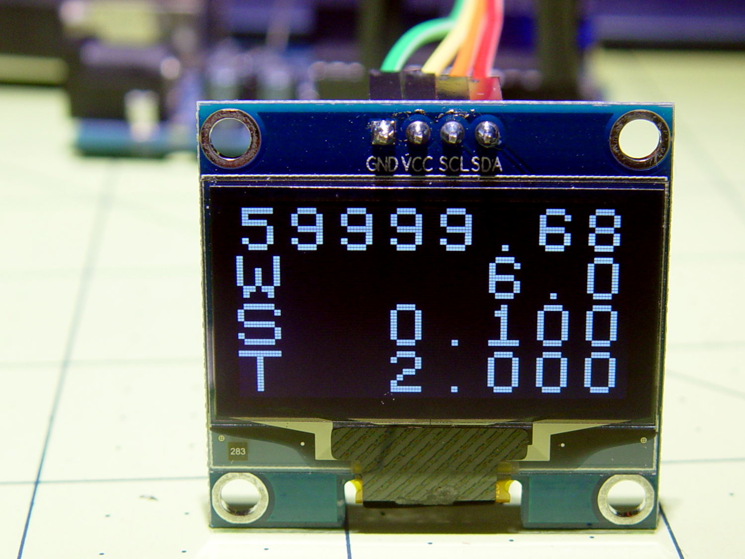
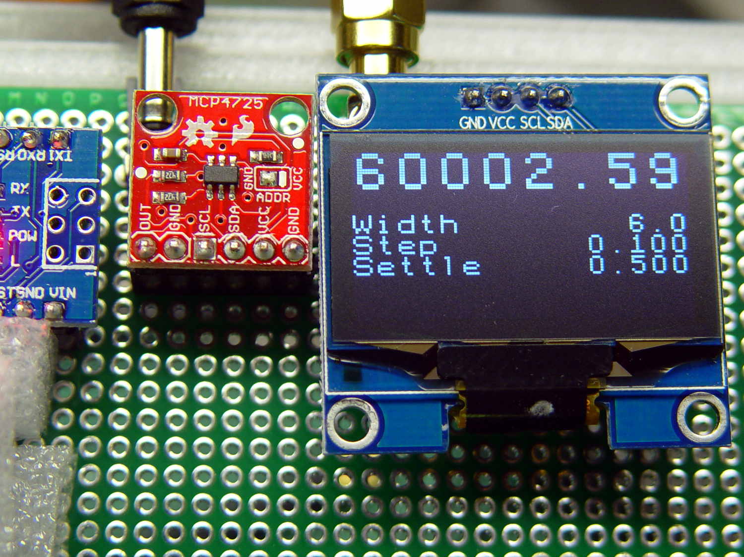
int ln = 0; |
|
u8x8.draw2x2String(0,ln,Buffer); |
|
ln += 2; |
|
|
|
TestFreq.fx_64 = ScanTo.fx_64 – ScanFrom.fx_64; |
|
PrintFixedPtRounded(Buffer,TestFreq,1); |
|
u8x8.draw2x2String(0,ln,"W "); |
|
u8x8.draw2x2String(2*(8-strlen(Buffer)),ln,Buffer); |
|
ln += 2; |
|
|
|
PrintFixedPtRounded(Buffer,ScanStep,3); |
|
u8x8.draw2x2String(0,ln,"S "); |
|
u8x8.draw2x2String(2*(8-strlen(Buffer)),ln,Buffer); |
|
ln += 2; |
|
|
|
TestFreq.fx_32.high = SCAN_SETTLE; // milliseconds |
|
TestFreq.fx_32.low = 0; |
|
TestFreq.fx_64 /= KILO; // to seconds |
|
PrintFixedPtRounded(Buffer,TestFreq,3); |
|
u8x8.draw2x2String(0,ln,"T "); |
|
u8x8.draw2x2String(2*(8-strlen(Buffer)),ln,Buffer); |
|
ln += 2; |
|
|
|
ScanFreq.fx_64 += ScanStep.fx_64; |
|
|
|
if (ScanFreq.fx_64 > (ScanTo.fx_64 + ScanStep.fx_64 / 2)) { |
|
ScanFreq = ScanFrom; |
|
} |
|
|
|
|
|
} |
|
|
|
} |
|
|
|
|