|
// Gooseneck lamp for MicroMark bandsaw |
|
// Ed Nisley KE4ZNU |
|
// February 2017 |
|
|
|
Layout = "Mount"; // Mount Show Build |
|
|
|
Gap = 5; // distance between halves for Show |
|
|
|
//- Extrusion parameters must match reality! |
|
|
|
ThreadThick = 0.25; |
|
ThreadWidth = 0.40; |
|
|
|
HoleWindage = 0.2; |
|
|
|
Protrusion = 0.1; // make holes end cleanly |
|
|
|
inch = 25.4; |
|
|
|
function IntegerMultiple(Size,Unit) = Unit * ceil(Size / Unit); |
|
|
|
//———————- |
|
// Dimensions |
|
|
|
Tap10_32 = 0.159 * inch; |
|
Clear10_32 = 0.190 * inch; |
|
Head10_32 = 0.373 * inch; |
|
Head10_32Thick = 0.110 * inch; |
|
Nut10_32Dia = 0.433 * inch; |
|
Nut10_32Thick = 0.130 * inch; |
|
Washer10_32OD = 0.381 * inch; |
|
Washer10_32ID = 0.204 * inch; |
|
|
|
ID = 0; // for round things |
|
OD = 1; |
|
LENGTH = 2; |
|
|
|
Insert = [3.0,4.9,2*ThreadThick + IntegerMultiple(4.2,ThreadThick)]; // M3 short brass insert |
|
|
|
CornerRadius = 5.0; // rounded mount block corners for pretty |
|
CornerSides = 4*4; |
|
|
|
RoundedTop = true; // true for fancy smooth top edges |
|
|
|
USBPlug = [39.0,16.0,8.3]; // plug, X from base of plug |
|
USBSocket = [28.0,20.0,11.5]; // USB extension, X from tip of socket |
|
|
|
USBMating = [-12.0,0,0]; // offset of plug base relative to block center |
|
|
|
Foam = [35.0,10.0,2.0 – 1.0]; // foam pad to secure USB plug (Z = thickness – compression) |
|
|
|
GooseneckOD = 5.0; // flexy gooseneck diameter |
|
|
|
MountScrewOC = 35.0; // make simple screw hole spacing for bandsaw case |
|
|
|
MountBlock = [10*round((USBPlug[0] + USBSocket[0] + 5.0)/10), |
|
10*round((MountScrewOC + Washer10_32OD + 5.0)/10), |
|
// 2*6*ThreadThick + IntegerMultiple(max(USBPlug[2],USBSocket[2]),ThreadThick)]; |
|
16.0]; // thickness = 16 mm M3x0.5 button head screw |
|
|
|
echo(str("Block size: ",MountBlock)); |
|
|
|
LegendDepth = 2*ThreadThick; // lettering depth |
|
|
|
//———————- |
|
// Useful routines |
|
|
|
module PolyCyl(Dia,Height,ForceSides=0) { // based on nophead's polyholes |
|
|
|
Sides = (ForceSides != 0) ? ForceSides : (ceil(Dia) + 2); |
|
|
|
FixDia = Dia / cos(180/Sides); |
|
|
|
cylinder(r=(FixDia + HoleWindage)/2, |
|
h=Height, |
|
$fn=Sides); |
|
} |
|
|
|
//– Mount |
|
|
|
module Mount() { |
|
|
|
difference() { |
|
hull() |
|
if (RoundedTop) { |
|
for (i=[-1,1], j=[-1,1]) |
|
translate([i*(MountBlock[0]/2 – CornerRadius),j*(MountBlock[1]/2 – CornerRadius),0]) { |
|
translate([0,0,-MountBlock[2]/2]) |
|
rotate(180/CornerSides) |
|
cylinder(r=CornerRadius,h=MountBlock[2]/2,$fn=CornerSides,center=false); |
|
translate([0,0,MountBlock[2]/2 – CornerRadius]) |
|
rotate(180/CornerSides) |
|
sphere(r=CornerRadius,$fn=CornerSides,center=true); |
|
} |
|
} |
|
else { |
|
for (i=[-1,1], j=[-1,1]) |
|
translate([i*(MountBlock[0]/2 – CornerRadius),j*(MountBlock[1]/2 – CornerRadius),0]) |
|
rotate(180/CornerSides) |
|
cylinder(r=CornerRadius,h=MountBlock[2],$fn=CornerSides,center=true); |
|
} |
|
for (j=[-1,1]) // screws into bandsaw case |
|
translate([0,j*MountScrewOC/2,-(MountBlock[2]/2 + Protrusion)]) |
|
rotate(180/8) |
|
PolyCyl(Clear10_32,(MountBlock[2] + 2*Protrusion),8); |
|
for (i=[-1,1], j=[-1,1]) { // clamp screws |
|
translate([i*MountBlock[0]/4,j*MountScrewOC/2,-MountBlock[2]]) |
|
PolyCyl(Insert[ID],2*MountBlock[2],6); // clearance |
|
translate([i*MountBlock[0]/4,j*MountScrewOC/2,-(MountBlock[2]/2 + Protrusion)]) |
|
PolyCyl(Insert[OD],Insert[LENGTH] + Protrusion,6); // inserts |
|
} |
|
rotate([0,90,0]) // gooseneck flexy cable |
|
rotate(180/6) |
|
PolyCyl(GooseneckOD,MountBlock[0],6); |
|
|
|
translate([USBPlug[0]/2,0,0] + USBMating – [Protrusion/2,0,0]) // USB plug outline |
|
cube(USBPlug + [Protrusion,0,0],center=true); |
|
translate([-USBSocket[0]/2,0,0] + USBMating) // USB socket outline |
|
cube(USBSocket,center=true); |
|
|
|
translate([(Foam[0]/2 + 5*ThreadWidth),0,-(Foam[2]/2 + USBPlug[2]/2)] + USBMating – [Protrusion,0,-Protrusion]/2) // foam padding recess |
|
cube(Foam + [Protrusion,0,Protrusion],center=true); // foam packing |
|
translate([(Foam[0]/2 + 5*ThreadWidth),0, (Foam[2]/2 + USBPlug[2]/2)] + USBMating – [Protrusion,0, Protrusion]/2) // foam padding recess |
|
cube(Foam + [Protrusion,0,Protrusion],center=true); |
|
|
|
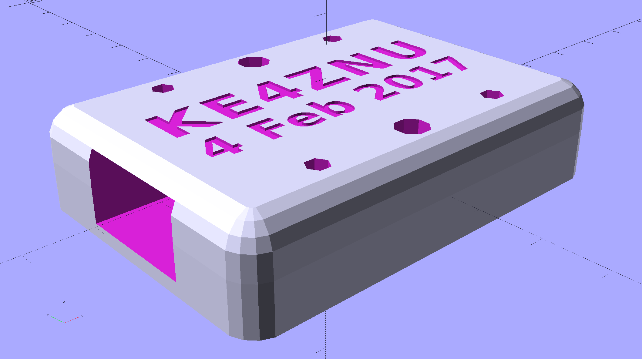
render(convexity=5) |
|
translate([0,0,MountBlock[2]/2 – LegendDepth]) |
|
linear_extrude(height=LegendDepth + Protrusion) { |
|
translate([0,5,0]) |
|
text(text="KE4ZNU",size=8,spacing=1.10,font="Bitstream Vera Sans:style=Bold",valign="center",halign="center"); |
|
translate([0,-5,0]) |
|
text(text="4 Feb 2017",size=6,spacing=1.05,font="Bitstream Vera Sans:style=Bold",valign="center",halign="center"); |
|
} |
|
} |
|
} |
|
|
|
//———————- |
|
// Build it |
|
|
|
if (Layout == "Mount") { |
|
Mount(); |
|
} |
|
|
|
if (Layout == "Show") { |
|
translate([0,0,-Gap/2]) |
|
difference() { |
|
Mount(); |
|
translate([0,0,MountBlock[2]]) |
|
cube(2*MountBlock,center=true); |
|
} |
|
translate([0,0,Gap/2]) |
|
difference() { |
|
Mount(); |
|
translate([0,0,-MountBlock[2]]) |
|
cube(2*MountBlock,center=true); |
|
} |
|
} |
|
|
|
if (Layout == "Build") { |
|
translate([0,0.6*MountBlock[1],MountBlock[2]/2]) |
|
difference() { |
|
Mount(); |
|
translate([0,0,MountBlock[2]]) |
|
cube(2*MountBlock,center=true); |
|
} |
|
translate([0,-0.6*MountBlock[1],MountBlock[2]/2]) |
|
rotate([180,0,0]) |
|
difference() { |
|
Mount(); |
|
translate([0,0,-MountBlock[2]]) |
|
cube(2*MountBlock,center=true); |
|
} |
|
} |