The Smell of Molten Projects in the Morning

Ed Nisley's Blog: Shop notes, electronics, firmware, machinery, 3D printing, laser cuttery, and curiosities. Contents: 100% human thinking, 0% AI slop.

Tag: Improvements

Making the world a better place, one piece at a time

  • Injured Arm Support Table: Wide Version

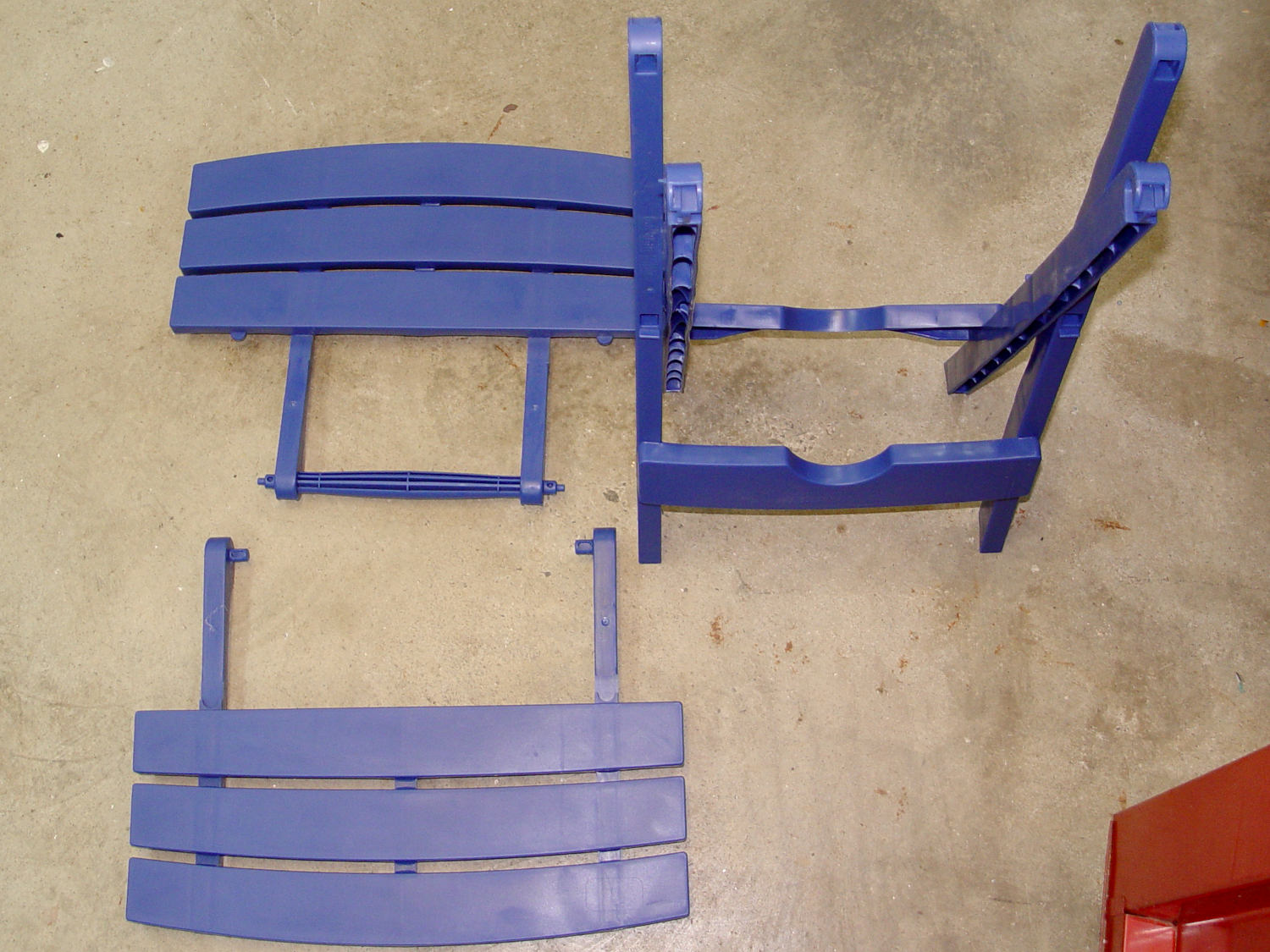
    This table must sit across the threshold of a walk-in / sit-down shower, with the shower curtain draped across the table to keep the water inside.

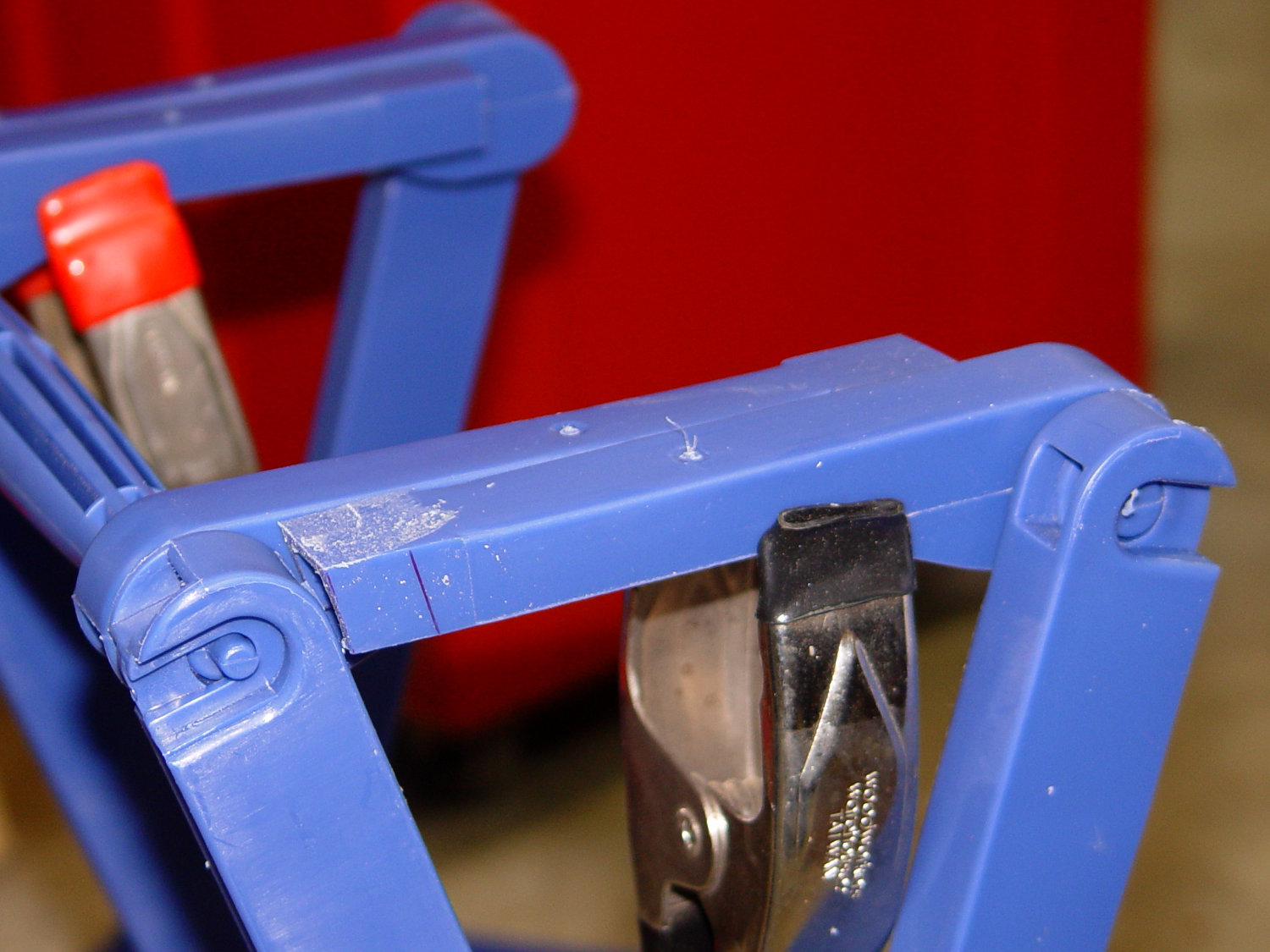
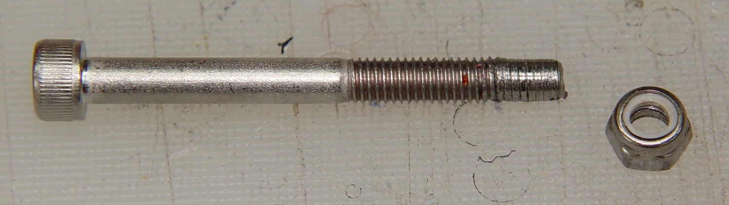
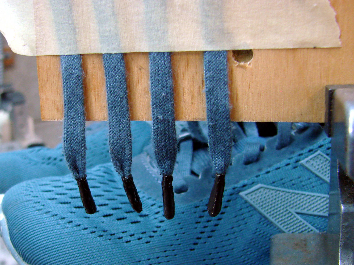
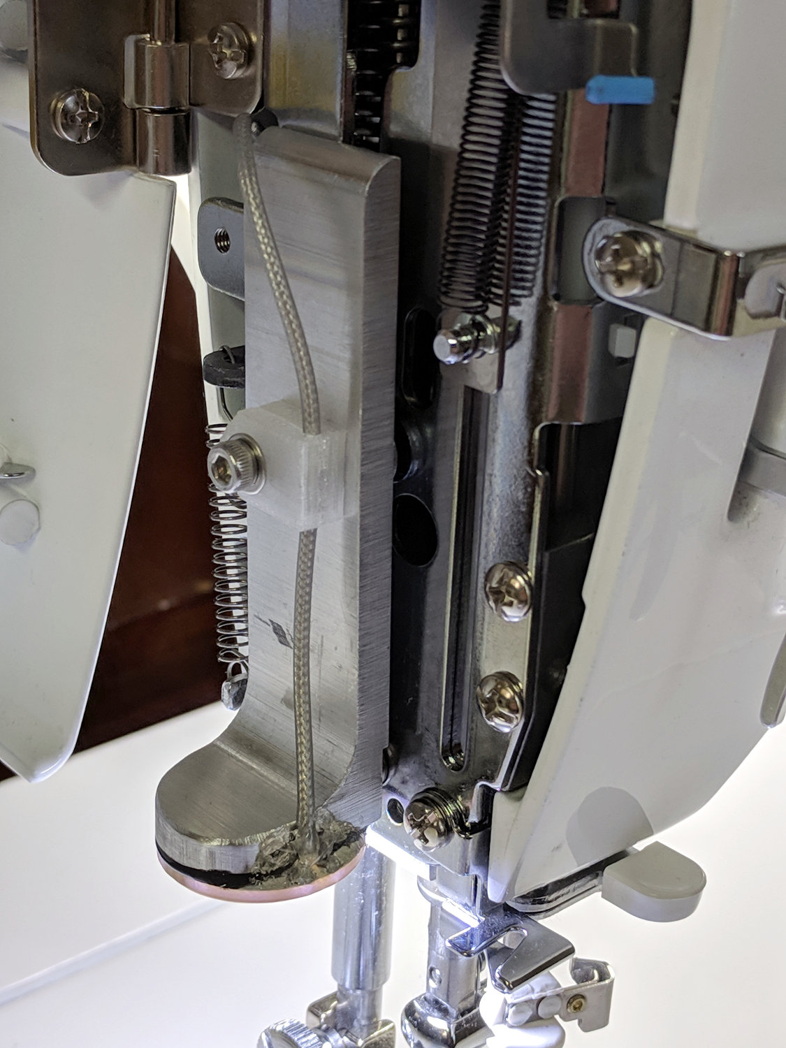
    Starting with another patio side table, as before, I installed a quartet of 5 mm stainless screws to lock the top panels in place and convert the table into a rigid assembly:

    Arm Supports - wide table - overview
    Arm Supports – wide table – overview

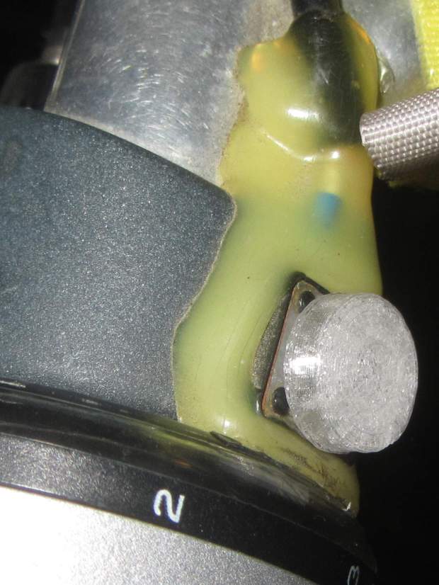
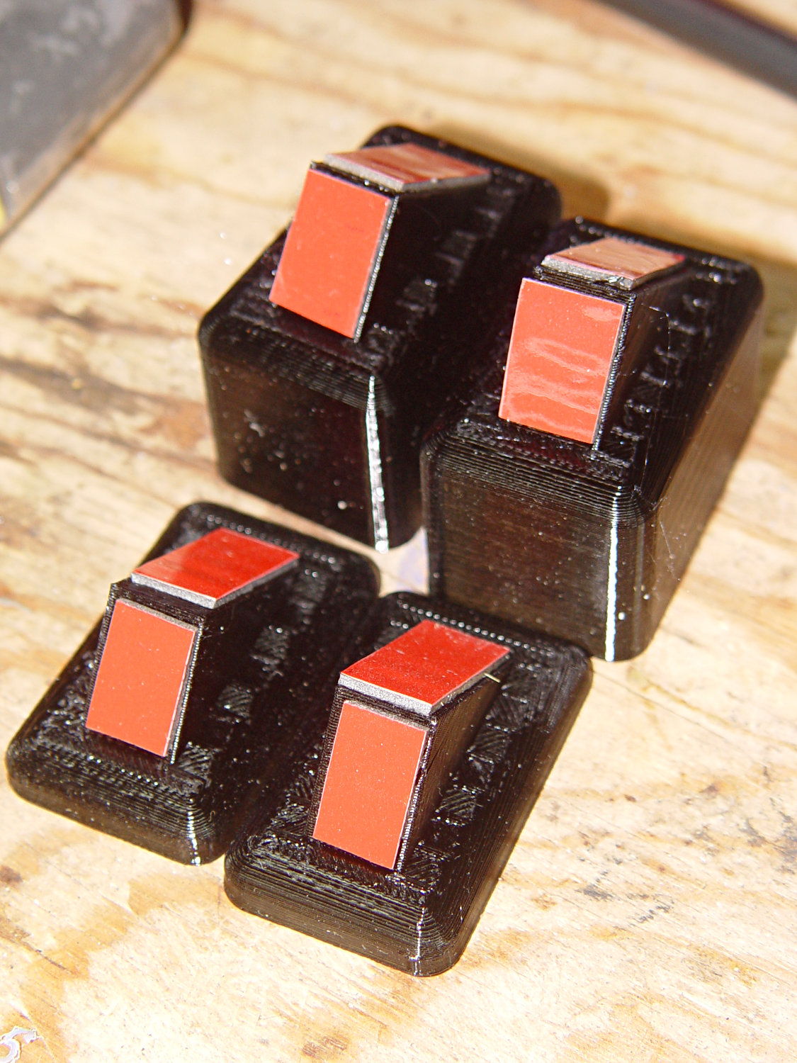
    Because the shower floor is slightly higher than the bathroom floor, I conjured a set of foot pads to raise the outside legs:

    Patio Side Table Feet - OpenSCAD model
    Patio Side Table Feet – OpenSCAD model

    The sloping top surface on the pads compensates for the angle on the end of the table legs:

    Arm Supports - leg end angle
    Arm Supports – leg end angle

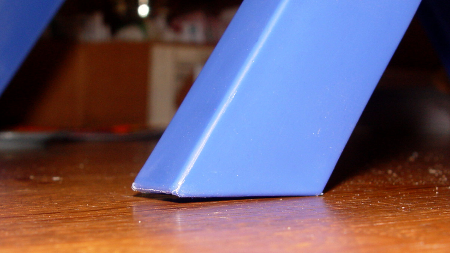
    I think the leg mold produces legs for several different tables, with the end angle being Close Enough™ for most purposes. Most likely, it’d wear flat in a matter of days on an actual patio.

    Using good 3M outdoor-rated foam tape should eliminate the need for fiddly screw holes and more hardware:

    Arm Supports - leg pads
    Arm Supports – leg pads

    The feet fit reasonably well:

    Arm Supports - leg pad in place
    Arm Supports – leg pad in place

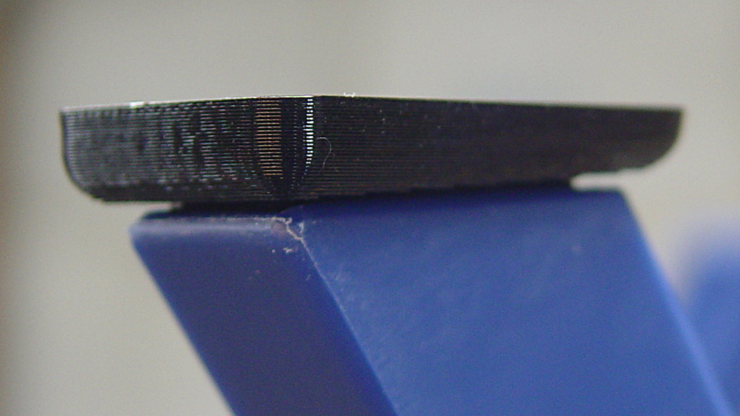
    They may need nonskid tape on those flat bottoms, but that’s in the nature of fine tuning.

    And, as with the narrow table, it may need foam blocks to raise the top surface to arm level. Perhaps a pair of Yoga Blocks will come in handy for large adjustments.

    The OpenSCAD source code as a GitHub Gist:

    // Patio Side Table Feet
    // Ed Nisley – KE4ZNU
    // 2019-03
    /* [Layout Options] */
    Layout = "Build"; // [Show,Build]
    /* [Extrusion Parameters] */
    ThreadWidth = 0.40;
    ThreadThick = 0.25;
    HoleWindage = 0.2;
    Protrusion = 0.1;
    //—–
    // Dimensions
    TapeThick = 1.0; // 3M double-stick outdoor tape
    LegWall = [2.5,3.5]; // leg walls are not the same in X and Y!
    LegBase = [36.0,19.0]; // flat on floor
    LegOuter = [31.0,19.0]; // perpendicular to leg axis
    LegInner = [28.5,11.5]; // … ditto
    LegAngle = 90 – 53; // vertical to leg
    LegRecess = [LegInner.x,LegInner.y,LegInner.x*tan(LegAngle)];
    PadWedge = 2; // to fit end of leg
    PadRadius = 4.0; // rounding radius for nice corners
    PadBase = [LegBase.x + 2*PadRadius,LegBase.y + 2*PadRadius,5.0];
    PadSides = 6*4;
    BathStep = 20; // offset between shower bottom and floor
    /* [Hidden] */
    EmbossDepth = 1*ThreadThick; // recess depth
    DebossHeight = 1*ThreadThick + Protrusion; // text height + Protrusion into part
    //—–
    // Useful routines
    function IntegerMultiple(Size,Unit) = Unit * ceil(Size / Unit);
    module PolyCyl(Dia,Height,ForceSides=0) { // based on nophead's polyholes
    Sides = (ForceSides != 0) ? ForceSides : (ceil(Dia) + 2);
    FixDia = Dia / cos(180/Sides);
    cylinder(r=(FixDia + HoleWindage)/2,
    h=Height,
    $fn=Sides);
    }
    //—–
    // Foot pad
    module FootPad(Riser = 0.0) {
    difference() {
    union() {
    hull()
    for (i=[-1,1], j=[-1,1]) {
    translate([i*(PadBase.x/2 – PadRadius),j*(PadBase.y/2 – PadRadius),0])
    cylinder(r=PadRadius,h=1,$fn=PadSides);
    translate([i*(PadBase.x/2 – PadRadius),
    j*(PadBase.y/2 – PadRadius),
    Riser + PadBase.z – PadRadius – (i-1)*PadWedge/2])
    sphere(r=PadRadius/cos(180/PadSides),$fn=PadSides);
    }
    translate([PadRadius – PadBase.x/2,0,Riser + PadBase.z])
    rotate([0,LegAngle,0])
    translate([LegRecess.x/2,0,(LegRecess.z – Protrusion)/2 ])
    cube(LegRecess – [2*TapeThick,0,2*TapeThick],center=true);
    }
    translate([0,0,-2*PadBase.z]) // remove anything under Z=0
    cube(4*PadBase,center=true);
    cube([17,12,2*DebossHeight],center=true);
    }
    mirror([1,0,0])
    linear_extrude(height=EmbossDepth)
    translate([0,0,0])
    text(text=str(Riser),size=10,spacing=1.05,
    font="Arial:style=Bold",
    valign="center",halign="center");
    }
    //—–
    // Build things
    if (Layout == "Build") {
    if (true) {
    translate([-0.7*PadBase.x,-0.7*PadBase.y,0])
    FootPad(0);
    translate([-0.7*PadBase.x,+0.7*PadBase.y,0])
    FootPad(0);
    }
    translate([+0.7*PadBase.x,-0.7*PadBase.y,0])
    FootPad(BathStep);
    translate([+0.7*PadBase.x,+0.7*PadBase.y,0])
    FootPad(BathStep);
    }
    if (Layout == "Show")
    FootPad();

  • Injured Arm Support Table: Narrow Version

    For reasons not relevant here, I recently conjured a pair of tables to support an injured arm (ours are OK!) in the bathroom: one table fitting in the narrow space adjacent to a toilet and the other across the threshold of a walk-in / sit-down shower.

    The raw material came from a plastic side table intended for outdoor use:

    Arm Supports - OEM Patio table
    Arm Supports – OEM Patio table

    That’s the Patriotic Blue version, which seemed the least offensive of the colors on offer at the local store.

    The plastic pieces unsnap easily enough:

    Arm Supports - top panel disassembly
    Arm Supports – top panel disassembly

    The legs also come apart by pulling outward at the crossover points. You may need to clean the flashing from all the joints, as they’re only as finished as absolutely necessary.

    A table about half the width seemed about right, so I sawed the two top plates off their struts, then angled the strut ends to match the new leg angle:

    Arm Supports - trimming table struts
    Arm Supports – trimming table struts

    Because it’s now completely floppy, I drilled holes for 5 mm screws through the struts:

    Arm Supports - cross-drilling struts
    Arm Supports – cross-drilling struts

    In the process, I discovered stainless steel nyloc nuts tend to gall on stainless steel screws:

    Galled stainless steel cap screw and nyloc nut
    Galled stainless steel cap screw and nyloc nut

    I lost a pair of screws + nuts before I got a clue and began adding a drop of machine oil to each screw before tightening the nuts. Haven’t had that problem with the 3 mm SS screws, so there’s always something new to learn.

    With all the screws in place, the half-table becomes a rigid contraption:

    Arm Supports - narrow table - bottom view
    Arm Supports – narrow table – bottom view

    The top looks like it’s suffering from severe barrel distortion, but it really started out looking that way:

    Arm Supports - narrow table - overview
    Arm Supports – narrow table – overview

    The slat sides are all curved, except the far edge that was once in the middle of the table and now fits against the wall.

    It may be slightly too short, but we can stack foam slabs on the top, probably held in place with cable ties.

    Memo to Self: lube all the stainless steel screws!

  • Improved Shoelace Ferrule Aglets

    After considerable evaluation, the Customer decided the shoelaces were still too long and said the hex-crimped ferrules were entirely too rough and tended to snag on things. This time, I prepared the ferrules by chucking them in the lathe:

    Ferrule - original flange
    Ferrule – original flange

    The steel rod inside the ferrule encourages it to remain round and not collapse while I’m filing off the flange that normally holds the plastic strain-relief doodad:

    Ferrule - reshaped flange
    Ferrule – reshaped flange

    I snipped another half inch off each end of the laces and crimped on the prepared ferrules:

    Shoelace ferrule aglets
    Shoelace ferrule aglets

    Which were definitely too jaggy, so they now sport an epoxy coat:

    Ferrule aglets - epoxy coat
    Ferrule aglets – epoxy coat

    Alas, JB Kwik epoxy has a pot life measured in minutes, so the last ferrule looks a bit lumpy. They seem to work fine and the Customer is happy with the results.

    Memo to Self: Next time, dunk the ferrules in a pot of slow-curing JB Weld and let them drain overnight.

  • ESR02 Test Clips

    An ANENG AN8009 multimeter recently arrived, complete with a bag of test probe parts, including a banana plug and an alligator clip crying out for a 3 mm threaded brass insert:

    Makeshift test clips
    Makeshift test clips

    A pair of them fit neatly into an ESR02 tester, where they provide tidy a low-inductance / low-capacitance “test fixture”:

    ESR02 with makeshift test clips
    ESR02 with makeshift test clips

    Admittedly, loading the part-under-test isn’t a one-handed operation, but it works reasonably well.

  • RD JDS6600 Signal Generator: Warmup Time

    An RD JDS6600 Signal Generator recently arrived from around the curve of the horizon, leading me to measure its warmup time:

    RDS6600 Signal Generator - Warmup plot
    RDS6600 Signal Generator – Warmup plot

    Looks like it’s good to go after maybe 90 minutes and, after much longer, it settles to 10 MHz +36 Hz, for a correction factor of 0.9999964 on those days when you’re being really fussy.

    The need for frequencies accurate to better than 4 ppm doesn’t happen very often around here, but it’s best to be prepared. It’s amazing what you can get for under $100 these days …

    I measured the frequency by zero-beating against the Z3801 GPS Frequency Standard (purple trace in the middle):

    RDS6600 Signal Generator vs. Z3801 GPS Frequency Standard
    RDS6600 Signal Generator vs. Z3801 GPS Frequency Standard

    Basically, trigger the scope on either trace, crank the JDS6600 frequency in 1 Hz, then 0.1 Hz steps, until the traces stop crawling past each other, and you’re done.

    It’s worth noting you (well, I) must crank eleven 0.01 Hz steps to change the output frequency by about 0.1 Hz around 10 MHz, suggesting the actual frequency steps are on the order of 0.1 Hz, no matter what the display resolution may lead you to think.

    The RDS6600 main PCB (Rev 15) sports a 24 MHz oscillator close to the Lattice FPGA:

    RDS6600 Signal Generator - clock oscillator
    RDS6600 Signal Generator – clock oscillator

    The AD9850 step size worked out to 0.0291 Hz for the LF crystal tester. A 24 MHz clock would produce a 5.7 mHz step size, but that’s obviously no what’s going on. More study is indicated.

    The bottom trace is the scope’s internal function generator, also set to 10 MHz. Zero-beating the JDS6600 against the scope’s output produces a similar result:

    IMG_20190312_130925 - RDS6600 vs SDS2304X frequencies
    IMG_20190312_130925 – RDS6600 vs SDS2304X frequencies

    The scope’s function generator actually runs at (9.999964 MHz) × (0.9999964) = 9.999928 MHz, a whopping 72 ppm low. The on-screen frequency measurements don’t have enough resolution to show the offset, nor to zero-beat it with the Z3801 input, so it’s as good as it needs to be.

    The Z3801’s double-oven oscillator takes a few days to settle from a cold start, so this wasn’t an impulsive measurement. Having the power drop midway through the process didn’t help, either, but it’s March in the Northeast and one gets occasional blizzards with no additional charge.

  • Tour Easy: SRAM Grip Bushing

    After installing the X.0 shifter, I sprang for new grips:

    Tour Easy - SRAM X.0 grip shifter - new grip with bushing
    Tour Easy – SRAM X.0 grip shifter – new grip with bushing

    They’re 90 mm long, which turned out to be 4 mm shorter than the grips that came with the bike; a close look showed the original ones were cut down from SRAM’s 110 mm grips.

    Well, I can fix that:

    Tour Easy - SRAM grip bushings
    Tour Easy – SRAM grip bushings

    Ordinarily, you’d just move the brake levers by 4 mm and declare victory. In this case, moving the right lever would be easy, but the left one is firmly glued in place by the radio’s PTT button:

    PTT Button - rounded cap
    PTT Button – rounded cap

    Believe me, solid modeling is easy compared to redoing that!

    The OpenSCAD source code doesn’t amount to much:

    // SRAM grip shifter bushings
    // Ed Nisley KE4ZNU March 2019
    
    Protrusion = 0.1;           // make holes end cleanly
    
    //----------------------
    // Dimensions
    
    ID = 0;
    OD = 1;
    LENGTH = 2;
    
    Bushing = [22.2 + 0.5,31.0,4.0];        // ID = E-Z slip fit
    
    NumSides = 2*3*4;
    
    //----------------------
    // Build it!
    
    difference() {
      cylinder(d=Bushing[OD],h=Bushing[LENGTH],$fn=NumSides);
      translate([0,0,-Protrusion])
        cylinder(d=Bushing[ID],h=Bushing[LENGTH] + 2*Protrusion,$fn=NumSides);
    }

    I loves me my 3D printer …

  • Juki TL-2010Q Needle LEDs: Installed!

    The combined illumination from the COB LED bar on the rear of the arm and the (renewed) COB LEDs over the needle does a pretty good job of lighting up the work area:

    Juki TL-2010Q Needle LEDs - cloth illumination
    Juki TL-2010Q Needle LEDs – cloth illumination

    That’s a staged shot with a quilt square from the top of the pile. You’d (well, Mary’d) sew along the lines, not across a finished square.

    The remaining deep shadows under the foot require an LED with an imaging lens on a gooseneck; precise piecing requires feeding fabric into the needle with alignment exactly where those shadows fall.

    The light levels look harsh and shadowy on the bare base:

    Juki TL-2010Q Needle LEDs - front
    Juki TL-2010Q Needle LEDs – front

    The shadow extending leftward from the needle comes from the arm’s shadow of the rear LED bar. The hotspot specular reflections of both LED arrays aren’t quite as glaring in real life, but a matte surface finish would be better.

    The needle LEDs sit on the bottom of the heatsink inside the endcap:

    Juki TL-2010Q Needle LEDs - installed
    Juki TL-2010Q Needle LEDs – installed

    The COB LED PCB has a weird pink tint, perhaps due to the silicone filter passing all the yellow and blue light downward, with red light reflected into the PCB.

    After one iteration, I settled on a 20 Ω 1 W ballast resistor:

    Juki TL-2010Q Needle LEDs - ballast resistor
    Juki TL-2010Q Needle LEDs – ballast resistor

    It drops 3.6 V to provide 180 mA of needle LED current and dissipates 640 mW, with the LEDs burning about 1.5 W to raise the heatsink just above room temperature. The extrusion on the rear arm is pleasantly warm and the resistors seem happy enough.

    Looks good to us and it’s much much much better than the feeble Juki needle LED.