The Smell of Molten Projects in the Morning

Ed Nisley's Blog: Shop notes, electronics, firmware, machinery, 3D printing, laser cuttery, and curiosities. Contents: 100% human thinking, 0% AI slop.

Tag: CNC

Making parts with mathematics

  • Extrusion Multiplier: Effects Thereof

    Part of the Curvelicious Cookie Cutter effort involved making the thinnest possible cutter blade wall consisting of two adjacent threads, because that’s about what the Afinia printer was producing (from a different model). My OpenSCAD code, based on an Inkscape model derived from the as-printed Afinia cutter, enlarges the cookie shape by a specific distance with a Minkowski sum; the model ultimately becomes G-Code directing the extruder nozzle around the outline.

    Obviously, that required a bit of fiddling:
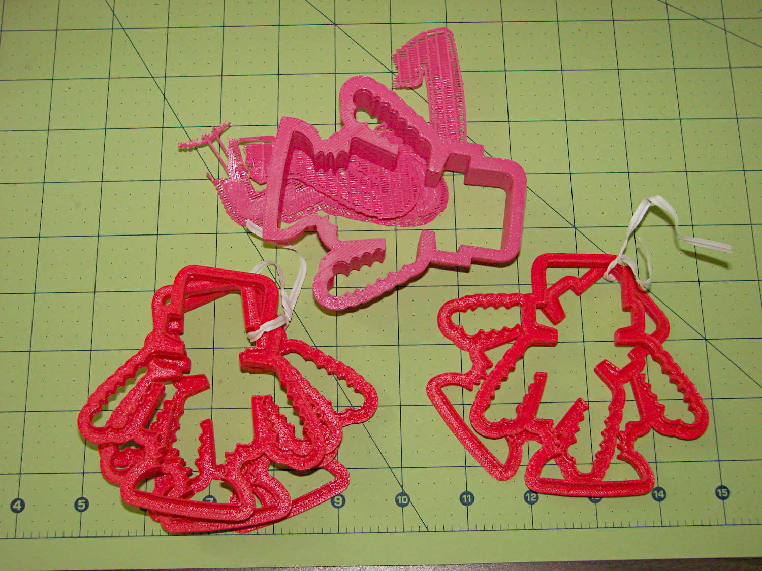
    Robot Cutter Variations
    Robot Cutter Variations

    The pink cutter on the top came from the Afinia, complete with raft. The red cutters, all with short blades to speed up the printing, came from my M2.

    The printer mechanics determine the step/mm values for all four axes: X, Y, Z, and the extruder. The effective diameter of the “gear” driving the filament into the extruder seems subject to some quibbling, but setting it so the thinwall box comes out with the proper filament width seems reasonable. Given those four values, the slicing software can control the extruder speed to produce the proper volume of plastic as the XY speed varies.

    The slicing software must also know the raw filament diameter, which seems to be consistent within a few percent for the filaments in my collection. Because a 1% change in filament diameter produces a 3% change in extruded volume, a few percent is about all you can tolerate; broad-tolerance filament may require sensors and adjustments that printers don’t currently offer.

    There is one remaining variable, essentially a Fudge Factor, which Slic3r calls the extrusion multiplier. This seems to be a linear factor applied to the extrusion volume, so that increasing the factor proportionally increase the flow rate. Given correct step/mm settings and the measured filament diameter, you (well, I) adjust the extrusion multiplier to get the proper extrusion flow. As it turned out, the multiplier I’ve been using with the M2 worked out to 1.00, although I’ve also used 0.97 on occasion. Although I haven’t read the Slic3r source code to verify this, varying the multiplier by +3% should fudge the diameter by about +0.017 mm = 1% of the measured 1.72 mm.

    Note that the Makergear-modified Marlin firmware in the M2 will produce different results, as they use a different value for the extruder gear’s effective diameter. More discussion on that is there.

    Soooo, I set up the extrusion multiplier to produce parts with accurate dimensions, because that’s what I care about, and didn’t worry too much about perfect surface finish, because I don’t really care about that. Cookie cutters, however, need a completely filled surface that prevents dough from collecting inside, but have essentially no dimensional accuracy requirements.

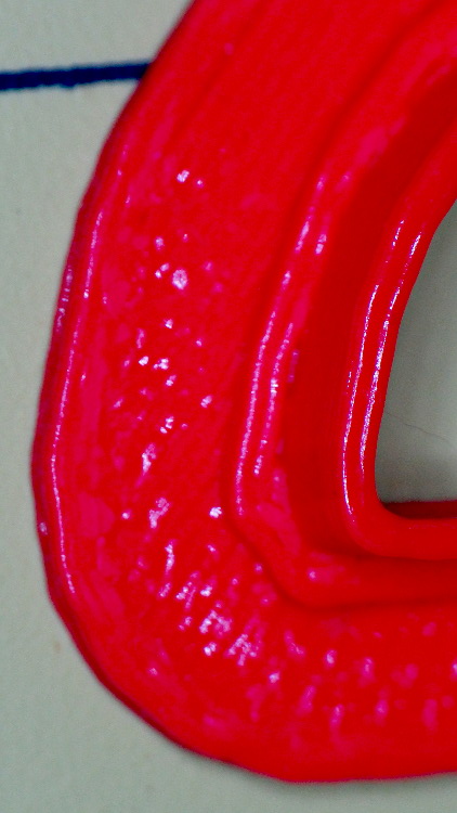
    The quartet of stumpy cutters bundled together on the left of the top photo explored the effect of changing the extrusion multiplier. I used the same STL model for all the cutters and varied only the extrusion factor, so the results depend only on the plastic flow rate and the M2’s impeccable mechanical stability.

    A sharp cusp at 0.96 has a slight opening:

    Robot Cutter - 0.96 extrusion multiplier
    Robot Cutter – 0.96 extrusion multiplier

    The cusp fills in at 1.10:

    Robot Cutter - 1.10 extrusion multiplier
    Robot Cutter – 1.10 extrusion multiplier

    The handle surface is slightly open at 0.96:
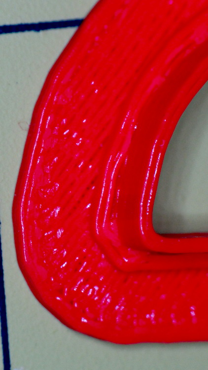
    Robot Cutter - 0.96 extrusion multiplier
    Robot Cutter – 0.96 extrusion multiplier

    And filled in at 1.10:

    Robot Cutter - 1.10 extrusion multiplier
    Robot Cutter – 1.10 extrusion multiplier

    In all those cases, the measured blade thickness varied slightly, but not enough to matter in this application. I didn’t record those numbers and no longer have the models, but … you just tune for best picture.

  • Reprap Cartridge Heaters from eBay

    I picked up five 12 V 40 W cartridge heaters from the usual eBay source for some extruder experiments and did a quick check to make sure they actually worked:

    Cartridge heater test
    Cartridge heater test

    The bench supply is good for 3 A, which isn’t quite enough to light them up all the way, but at 8 V they drew anywhere from 2.67 to 2.20 A, declining by about 0.1 A as they heated over the course of maybe 5 s, which is about as long as you want to run them outside of whatever they’re supposed to be heating.

    Those dissipations are a bit lower than I expected; at 8 V you’d expect to see about 27 W = 2/3 * 40 W, not the 18 to 21 W I actually measured. Current & power don’t scale linearly, so I must gimmick up a larger block and make some better measurements when I get the LinuxCNC hardware set up.

    The insulating tubes on the wires emerging from the cartridge, inside the main sheath, show the usual attention to detail I’ve come to know and love from eBay suppliers:

    Cheap cartridge heater insulation
    Cheap cartridge heater insulation

    Ah, well, it keeps my toy budget under control…

    There’s a story behind the dark vertical smudge just to the right of the cartridge. More on that in a bit.

  • Edge-Lit Acrylic “Nixie” Display: Doodles

    The Basement Warehouse Wing has an essentially unlimited supply of pristine CD cases (remember CDs?) that, with a bit of deft bandsaw work, will each emit a pair of 4×4 inch sheets of perfectly transparent acrylic plastic. The sheets are about 1.3 mm = 50 mils thick, which is just about exactly what you want for a Nixie-style display that doesn’t require high voltages, because you can edge-light a sheet with 0603 amber SMD LEDs. Obviously, this is not a Shining New Idea, but this post collects my doodles so they don’t get lost along the way.

    The Squidwrench StickerLab session prodded me into lashing a prototype together to see how this would work; they have a Silhouette Cameo vinyl cutter driven with Robotcut that works well. I’d hoped to do some laser cutting at the subsequent session, but our schedules didn’t mesh.

    The compelling advantage of laser cutting is that you could crack the CD cases apart, throw out the CD holder gimcrackery, lay the sheets flat on the cutter table with the latches & other junk upward, and burn the digits out of the middle without any further preparation. I think I could get much the same effect, at least for a crude prototype, by milling & engraving with the Sherline.

    The sheets are about 4 threads of 3D printed plastic extruded at the M2’s default 0.4 mm width. You could print a black baseplate with slots to hold the sheets, put two threads between each sheet, and have the sheet 6 threads apart on center = 2.4 mm spacing:

    Tab vs 3D thread size doodle
    Tab vs 3D thread size doodle

    Ten such sheets would produce a standard 0-to-9 display about an inch deep, plus protective sheets front and back, so the whole affair would be maybe 1.25 inch deep. You’d probably want to offset the tabs on adjacent sheets to reduce light leakage between LEDs. The baseplate fits atop a PCB with LEDs at the right locations, so you get an opaque holder for the sheets that’s easy to produce and easy to assemble:

    Sheet tab layout doodle
    Sheet tab layout doodle

    If you were clever, you could have different tab locations on each sheet so they’d fit only in the proper orientation; that might be important for cough mass production.

    The M2 has a platform big enough to build an entire clock base in one pass, plus a matching piece to capture the tops of the digits. I think edge-lit acrylic needs a complete opaque surround for each digit sheet to block light leaking from the edges; it might be easier to build the mount in the other direction, lying flat on the platform, stack the mounts together with the digit sheets, then bolt the whole assembly from the front; that would ensure perfect alignment of everything.

    In that case, the 3D printed layers are 0.25 mm (or smaller), but the resolution for the tabs would be 0.4 mm. If you were exceedingly brave & daring, you could lay the digit sheets in place during the build and come out with a monolithic unit; that might require a bit of clearance atop each sheet, as a grazing touch from a hot nozzle would be painfully obvious.

    There’s no reason you couldn’t have 16 sheets for a hexadecimal display; this would work out nicely with 8-bit shift registers using SPI from the usual Arduino-love controller. One might prefer current-limiting LED drivers.

    There’s also no reason you couldn’t use a wider “digit” sheet and engrave, say, the days of the week or the units of measurement or something like that on each panel.

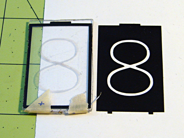
    If the display will be 30 mm deep, then the digits must be large enough that the depth doesn’t turn each digit into a tunnel. Large Nixe tubes had digits about 40 mm tall, so I went with a 30 x 45 panel, plus 1 mm tabs on the top and bottom:

    Crude edge-lit acrylic panel vs vinyl stencil
    Crude edge-lit acrylic panel vs vinyl stencil

    The “engraved” digit on the left came from a vinyl mask similar to the one on the right, using fine sandpaper to rough up the acrylic surface. I deliberately started with a battered old CD case in order to prevent myself from getting too compulsive with neatness; as you’ll see, edge-lit acrylic reveals any surface imperfections, so cleanliness is important.

    The black border could be a light-shield gasket around the outer edge of the display panel to reduce glare from the edges. This might be more important for laser-cut pieces with highly reflective edges or for milled pieces with diffuse edges; there’s no way to tell without actually building one to see. I simply bandsawed the sheet around the edges of the mask, then filed off the larger chunks: the edges are very, very rough, indeed.

    There doesn’t seem to be an easy way to stash the Inkscape SVG file on WordPress.

    I solder-blobbed some wire-wrap wire, a 1206 SMD resistor, and a 0603 LED together:

    Crude 0603 SMD LED lashup
    Crude 0603 SMD LED lashup

    The 0603 SMD LED fits neatly along the edge of the sheet:

    0603 SMD on CD case edge
    0603 SMD on CD case edge

    A 3rd hand holds it upright on the bench over the LED lashup:

    Edge-lit acrylic - front layout
    Edge-lit acrylic – front layout

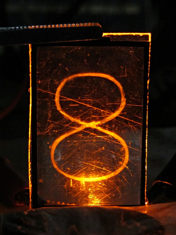
    It looks marginally better with the lights out, but you can see all the scratches:

    Edge-lit acrylic - front detail
    Edge-lit acrylic – front detail

    The hot spot at the bottom of the digit isn’t nearly that awful in person.

    A top view shows the glowing edges, plus the nuclear glow from the LED:

    Edge-lit acrylic - top view
    Edge-lit acrylic – top view

    A touch of soft focus, plus moving the LED under a tab location, helps a bit:

    Edge-lit acrylic - front soft focus
    Edge-lit acrylic – front soft focus

    You’d want two LEDs per digit and maybe one at the top, but that’s in the nature of fine tuning.

    All in all, I like how it looks. Getting from this crud to a workable display will require far more effort than I can devote to it right now…

  • Makergear M2: Bridge Torture Test

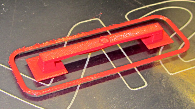
    Although I’ve pretty much given up on torture tests, I saw a note about the troubles someone had with Triffid Hunter’s Bridge Torture Test object. I did a bit of tweaking to the OpenSCAD source to shorten the struts and add the pads (which could be done with Slic3r’s Brim settings), but it’s otherwise about the same. The clear span is about 50 mm:

    Bridge Torture Test - solid model
    Bridge Torture Test – solid model

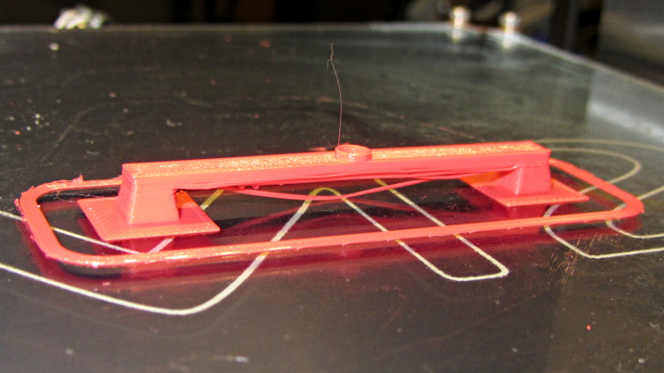
    Using my usual settings, with no special setup, the front looked OK:

    Bridge torture test - overview
    Bridge torture test – overview

    One strand came out rather droopy:

    Bridge torture test - front
    Bridge torture test – front

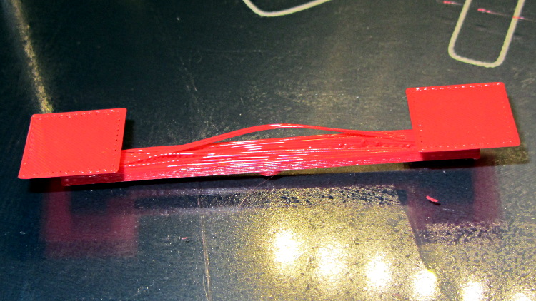
    The bottom layer of the bridge isn’t as consolidated as it could be:

    Bridge torture test - bottom
    Bridge torture test – bottom

    The overall speed dropped considerably as the Cool setting limited the layer time to 20 seconds; the Bridge settings didn’t apply.

    I could probably tighten the bottom strands a bit, but it’s OK for a first pass.

    The OpenSCAD source code:

    bridge_length = 50;
    bridge_angle = 0;
    bridge_width = 5;
    
    strut_height = 4;
    
    layer_height = 0.25;
    extrusion_width = 0.5;
    
    bridge_recovery_layers = 2 / layer_height;
    
    module foot() {
    	rotate([0, 0, 180/4]) cylinder(r=bridge_width * 2, h=layer_height, $fn=4);
    }
    
    module strut() {
    	rotate([0, 0, 180/4])
    	difference() {
    		cylinder(r1=bridge_width / 1.5 / cos(45), r2=bridge_width / 2 / cos(45),
    			h=strut_height, $fn=4);
    		translate([0, 0, -1]) cylinder(r1=(bridge_width / 1.5 - extrusion_width * 2) / cos(45),
    			r2=(bridge_width / 2 - extrusion_width * 2) / cos(45), h=10, $fn=4);
    	}
    }
    
    translate([-bridge_length/2,0,0])
    rotate(bridge_angle) {
    	translate([00, 0, 0]) foot();
    	translate([bridge_length + bridge_width, 0, 0]) foot();
    
    	translate([00, 0, 0]) strut();
    	translate([bridge_length + bridge_width, 0, 0]) strut();
    
    	translate([bridge_width / -2, bridge_width / -2, strut_height]) cube([bridge_length + bridge_width * 2, bridge_width, layer_height * bridge_recovery_layers]);
    
    	translate([bridge_length / 2 + bridge_width / 2, 0, strut_height + layer_height * bridge_recovery_layers])
    	difference() {
    		cylinder(r=bridge_width / 2, h=1, $fn=32);
    		cylinder(r=bridge_width / 2 - extrusion_width, h=1.01, $fn=32);
    	}
    }
    
  • Cheap Boost Power Supply Evaluation

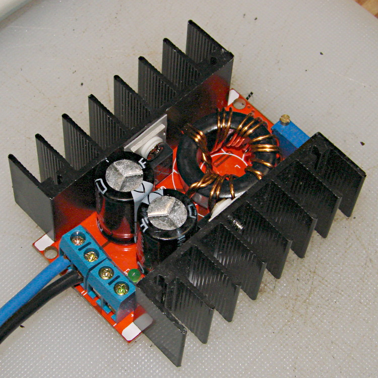
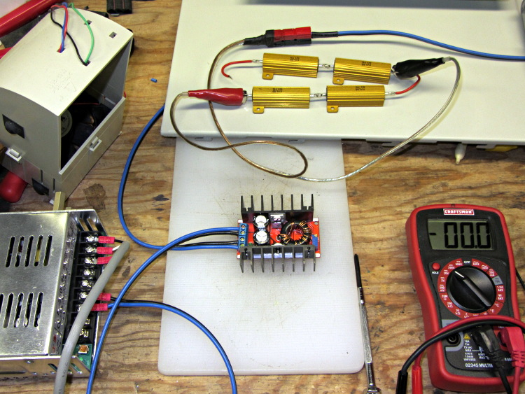
    For reasons that will become apparent in a while, I got a pair (*) of boost power supplies from the usual eBay source, allegedly capable of boosting a 10-to-32 VDC input to a 12-to-35 VDC output, up to 10 A and 150 W:

    Boost power supply
    Boost power supply

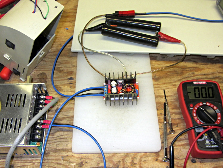
    After establishing that it would not produce 30 V into a 5.9 Ω load (5.1 A, but 152 W), I got systematic.

    A 100 Ω resistor drew 1/4 A while I set the output to 28 V. Doubling up the resistors showed that it worked OK at half an amp:

    Boost supply - 50 ohm load
    Boost supply – 50 ohm load

    Four 6 Ω resistors in series draw 1.2 A, then (channeling the true spirit of DIY 3D printing) two in series drew 2.3 A:

    Boost supply - 12 ohm load
    Boost supply – 12 ohm load

    That’s 32 W each and, yes, they did get toasty, but, no, I didn’t leave them turned on all that long.

    But a 6 Ω resistance still didn’t work, so the supply can’t provide 4.7 A at 130 W. In case you were wondering, that’s two 6 Ω resistors in series and a pair of those strings in parallel, so each resistor still sees 32 W.

    In terms of driving the actual load, these supplies aren’t going to light it up.

    Ah, well, whaddaya want for five buck from halfway around the planet?

    (*) Davy’s Aphorism: Never buy only one of any surplus item, because you’ll never find another. Get at least two, maybe three if it’s something you might actually use.

  • Creating a Curvelicious Cookie Cutter

    So, for reasons I need not go into, I needed an OpenSCAD solid model of a custom cookie cutter produced on an Afinia 3D printer from a Trimble Sketchup model:

    Afinia Robot Cutter - on raft
    Afinia Robot Cutter – on raft

    The cutter is still attached to the raft that, it seems, is required for passable results on the Afinia’s platform.

    Having already figured out how to wrap a cutter around a shape, the most straightforward procedure starts by extracting the cutter’s shape. So, lay the cutter face down on the scanner and pull an image into GIMP:

    Afinia Robot - scan
    Afinia Robot – scan

    Blow out the contrast to eliminate the background clutter, then posterize to eliminate shadings:

    Afinia Robot - scan enhanced
    Afinia Robot – scan enhanced

    Select the black interior region, grow the selection by a pixel or two, then shrink it back to eliminate (most of) the edge granularity, plunk it into a new image, and fill with black:

    Afinia Robot - scan filled
    Afinia Robot – scan filled

    Now the magic happens…

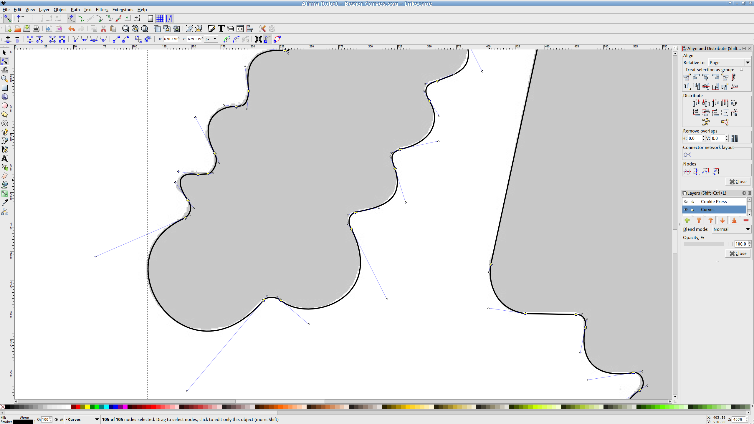
    Import the bitmap image into Inkscape. In principle, you can auto-trace the bitmap outline and clean it up manually, but a few iterations of that convinced me that it wasn’t worth the effort. Instead, I used Inkscape’s Bézier Curve tool to drop nodes (a.k.a. control points) at all the inflection points around the image, then warped the curves to match the outline:

    Afinia Robot - Bezier spline fitting
    Afinia Robot – Bezier spline fitting

    If you’re doing that by hand, you could start with the original scanned image, but the auto-trace function works best with a high-contrast image and, after you give up on auto-tracing, you’ll find it’s easier to hand-trace a high-contrast image.

    Anyhow, the end result of all that is a smooth path around the outline of the shape, without all the gritty details of the pixelated version. Save it as an Inkscape SVG file for later reference.

    OpenSCAD can import a painfully limited subset of DXF files that, it seems, the most recent versions of Inkscape cannot produce (that formerly helpful tutorial being long out of date). Instead, I exported (using “Save as”) the path from Inkscape to an Encapsulated Postscript file (this is a PNG, as WordPress doesn’t show EPS files):

    Afinia Robot - Bezier Curves.eps
    Afinia Robot – Bezier Curves.eps

    It’s not clear what the EPS file contains; I think it’s just a list of points around the path that doesn’t include the smooth Bézier goodness. That may account for the grittiness of the next step, wherein the pstoedit utility converts the EPS file into a usable DXF file:

    pstoedit dxf:-polyaslines Afinia\ Robot\ -\ Bezier\ Curves.eps Afinia\ Robot\ -\ outline.dxf
    

    Unfortunately, either the EPS file doesn’t have enough points on each curve or pstoedit automatically sets the number of points and doesn’t provide an override: contrary to what you (well, I) might think, the -splineprecision option doesn’t apply to whatever is in the EPS file. In any event, the resulting DXF file has rather low-res curves, but they were good enough for my purposes and OpenSCAD inhaled the DXF and emitted a suitable STL file:

    Afinia Robot - shape slab
    Afinia Robot – shape slab

    To do that, you set the Layout variable to “Slab”, compile the model, and export the STL.

    Being interested only in the process and its results, not actually cutting and baking cookies, I tweaked the OpenSCAD parameters to produce stumpy “cutters”:

    Afinia Robot - solid model
    Afinia Robot – solid model

    You do that by setting the Layout variable to “Build”, compile the model, and export yet another STL. In the past, this seemed to be a less fragile route than directly importing and converting the DXF at each stage, but that may not be relevant these days. In any event, having an STL model of the cookie may be useful in other contexts, so it’s not entirely wasted effort.

    Run the STL through Slic3r to get the G-Code as usual.

    The resulting model printed in about 20 minutes apiece on the M2:

    Robot Cutter - stumpy version
    Robot Cutter – stumpy version

    As it turns out, the fact that the M2 can produce ready-to-use cutters, minus the raft, is a strong selling point.

    Given a workable model, the next step was to figure out the smallest possible two-thread-wide cutter blade, then run variations of the Extrusion Factor to see how that affected surface finish. More on that in a while.

    The OpenSCAD source isn’t much changed from the original Tux Cutter; the DXF import required different scale factors:

    // Robot cookie cutter using Minkowski sum
    // Ed Nisley KE4ZNU - Sept 2011
    // August 2013 adapted from the Tux Cutter
    
    Layout = "Build";				// Build Slab
    
    //- Extrusion parameters - must match reality!
    
    ThreadThick = 0.25;
    ThreadWidth = 0.40;
    
    function IntegerMultiple(Size,Unit) = Unit * ceil(Size / Unit);
    
    MaxSize = 150;				// larger than any possible dimension ...
    
    Protrusion = 0.1;
    
    //- Cookie cutter parameters
    
    Size = 95;
    
    TipHeight = IntegerMultiple(3.0,ThreadThick);
    TipThick = 1.5*ThreadWidth;			// 1.5* = thinnest 2-thread wall, 1.0* thread has gaps
    
    WallHeight = IntegerMultiple(1.0,ThreadThick);
    WallThick = 4.5*ThreadWidth;
    
    LipHeight = IntegerMultiple(1.0,ThreadWidth);
    LipThick = IntegerMultiple(5,ThreadWidth);
    
    //- Wrapper for the shape of your choice
    
    module Shape(Size) {
      Robot(Size);
    }
    
    //- A solid slab of Tux goodness in simple STL format
    // Choose magic values to:
    //		center it in XY
    //		reversed across Y axis (prints with handle on bottom)
    //		bottom on Z=0
    //		make it MaxSize from head to feet
    
    module Tux(Scale) {
      STLscale = 250;
      scale(Scale/STLscale)
    	translate([105,-145,0])
    	  scale([-1,1,24])
    		import(
    		  file = "/mnt/bulkdata/Project Files/Thing-O-Matic/Tux Cookie Cutter/Tux Plate.stl",
    		  convexity=5);
    }
    
    module Robot(Scale) {
        STLscale = 100.0;
        scale(Scale / STLscale)
    			scale([-1,1,10])
    				import("/mnt/bulkdata/Project Files/Thing-O-Matic/Pinkie/M2 Challenge/Afinia Robot.stl",
    					convexity=10);
    }
    
    //- Given a Shape(), return enlarged slab of given thickness
    
    module EnlargeSlab(Scale, WallThick, SlabThick) {
    
    	intersection() {
    	  translate([0,0,SlabThick/2])
    		cube([MaxSize,MaxSize,SlabThick],center=true);
    	  minkowski(convexity=5) {
    		Shape(Scale);
    		cylinder(r=WallThick,h=MaxSize,$fn=16);
    	  }
    	}
    
    }
    
    //- Put peg grid on build surface
    
    module ShowPegGrid(Space = 10.0,Size = 1.0) {
    
      RangeX = floor(100 / Space);
      RangeY = floor(125 / Space);
    
    	for (x=[-RangeX:RangeX])
    	  for (y=[-RangeY:RangeY])
    		translate([x*Space,y*Space,Size/2])
    		  %cube(Size,center=true);
    
    }
    
    //- Build it
    
    ShowPegGrid();
    
    if (Layout == "Slab")
    	Shape(Size);
    
    if (Layout == "Build")
    	difference() {
    	union() {
    		translate([0,0,(WallHeight + LipHeight - Protrusion)])
    		EnlargeSlab(Size,TipThick,TipHeight + Protrusion);
    		translate([0,0,(LipHeight - Protrusion)])
    		EnlargeSlab(Size,WallThick,(WallHeight + Protrusion));
    		EnlargeSlab(Size,LipThick,LipHeight);
    	}
    	Shape(Size);					// punch out cookie hole
    	}
    
  • Storm Door Latch: Repair Parts

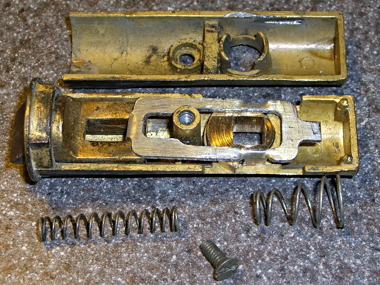
    The discussion following that post on getting feature coordinates from an existing part reminded me of an old project that I’d written up for Digital Machinist: making repair parts for the half-century old storm doors on our house. Here’s the whole latch, with a replacement drawbar and cam:

    Latch Assembly
    Latch Assembly

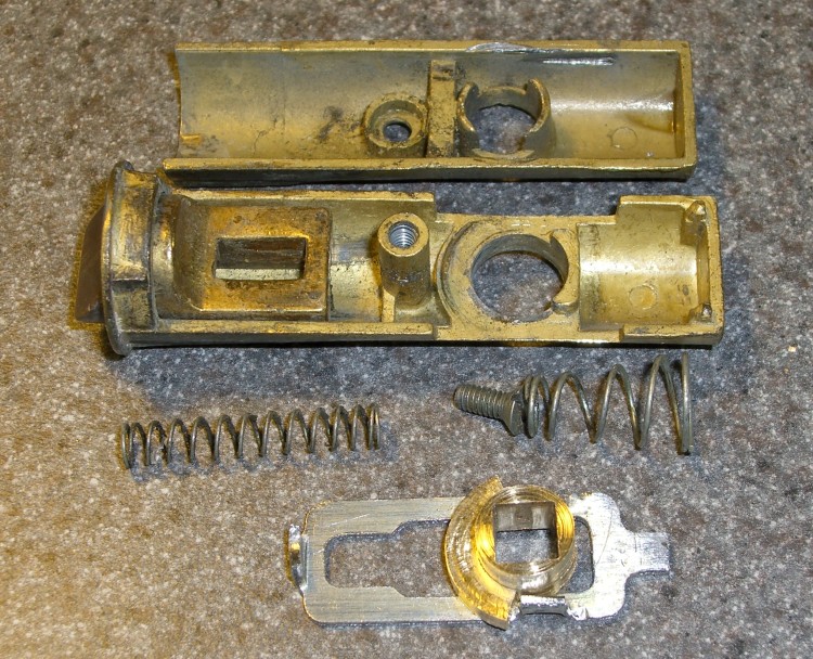
    The other side of the drawbar and cam:

    Door Latch Parts
    Door Latch Parts

    An early version of the drawbar that engages the latch strike and gets pulled by cam:

    New and Old latch pulls
    New and Old latch pulls

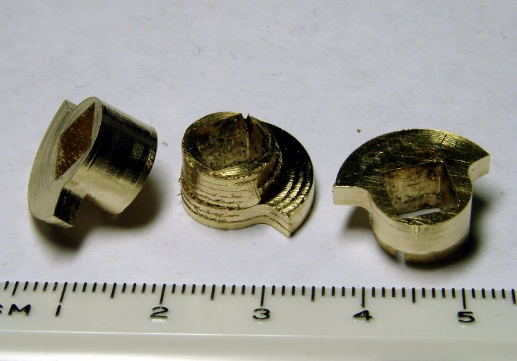
    Three iterations on a cam; the messed-up one in the center, IIRC, helped track down an EMC2 bug:

    Latch Cams
    Latch Cams

    Now that I look at it again, there’s nowhere near enough meat around that square hole for a 3D printed plastic part… so the notion of printing the complex part of the cam and adding wear bars along those ears just isn’t going to work.

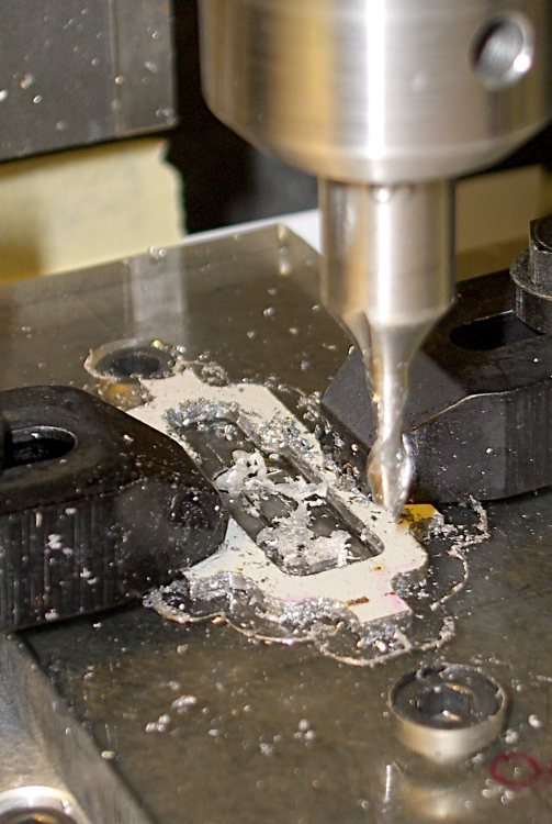
    I made a fixture for the Sherline CNC mill to hold the drawbar for inside milling:

    Latch pull - Inside milling
    Latch pull – Inside milling

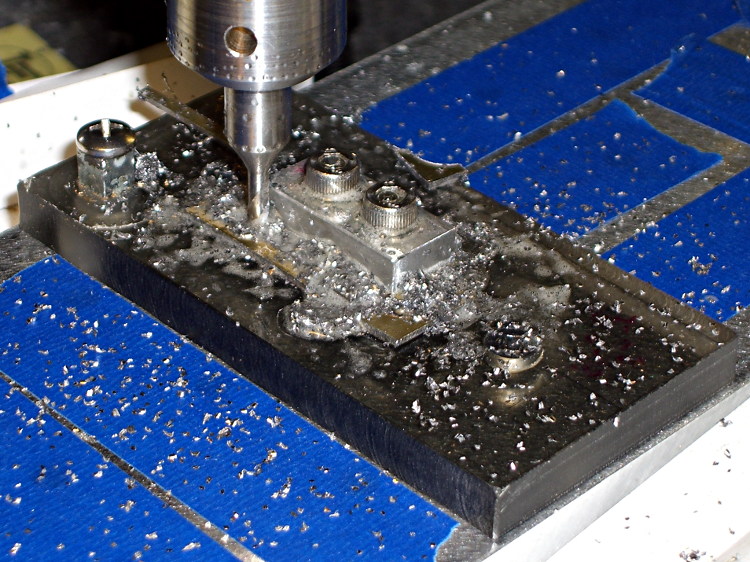
    Then a block screwed down in the middle clamps the drawbar in the same place for outside milling:

    Latch pull - Outside milling
    Latch pull – Outside milling

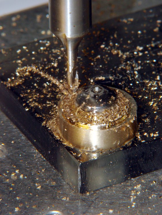
    The square post in the left rear corner holds the cam:

    Latch Cam - First Attempt
    Latch Cam – First Attempt

    Note that I had to file the square hole before milling the cam shape, which meant that if the CNC process screwed up, all that handwork went into the show-n-tell bin… which I’m not going to show you.

    I used an early version of the grid-overlay technique to map out the drawbar coordinates; this was an illustration for the column:

    Latch Pull Dimensions
    Latch Pull Dimensions