The Smell of Molten Projects in the Morning

Ed Nisley's Blog: Shop notes, electronics, firmware, machinery, 3D printing, laser cuttery, and curiosities. Contents: 100% human thinking, 0% AI slop.

Tag: CNC

Making parts with mathematics

  • Sherline Tommy Bar Handles

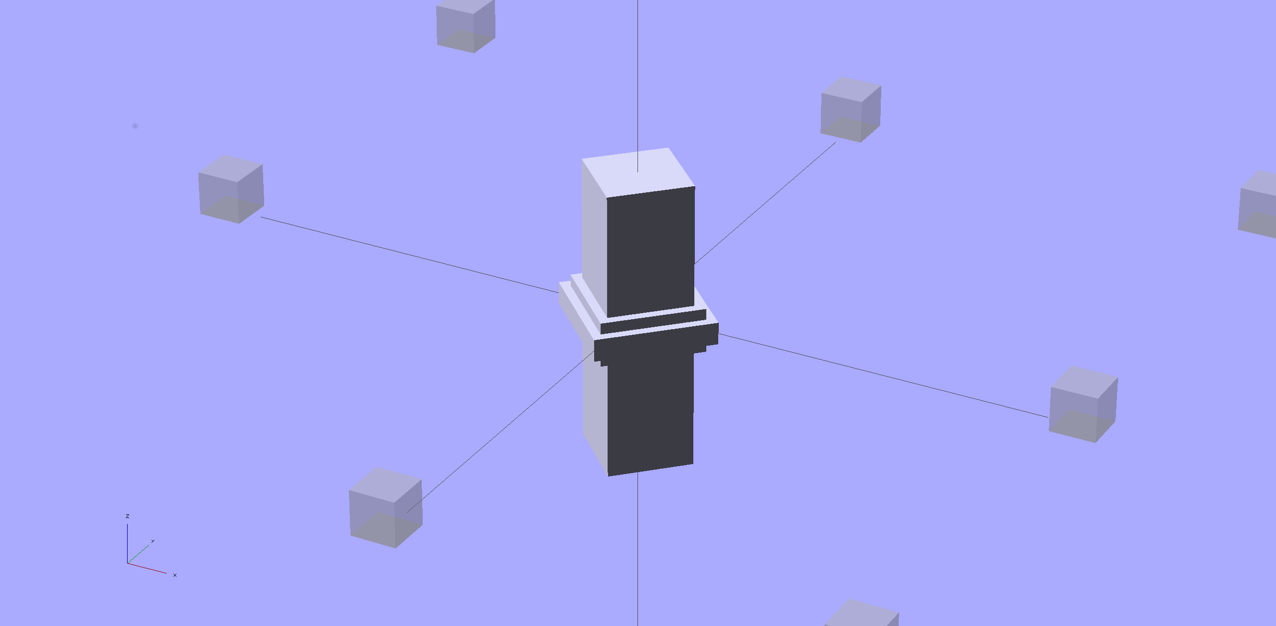
    While putting the speed wrenches in the box with the Sherline four-jaw chuck, it occurred to me that I had all the makings of a handle for Sherline’s steel tommy bars:

    Sherline Tommy Bar Handle - solid model
    Sherline Tommy Bar Handle – solid model

    Because these are intended for pushing, rather than twisting, I dialed the knurl back to 32 DP, reduced the depth to 0.5 mm, and ran the bar almost all the way through the handle for strength:
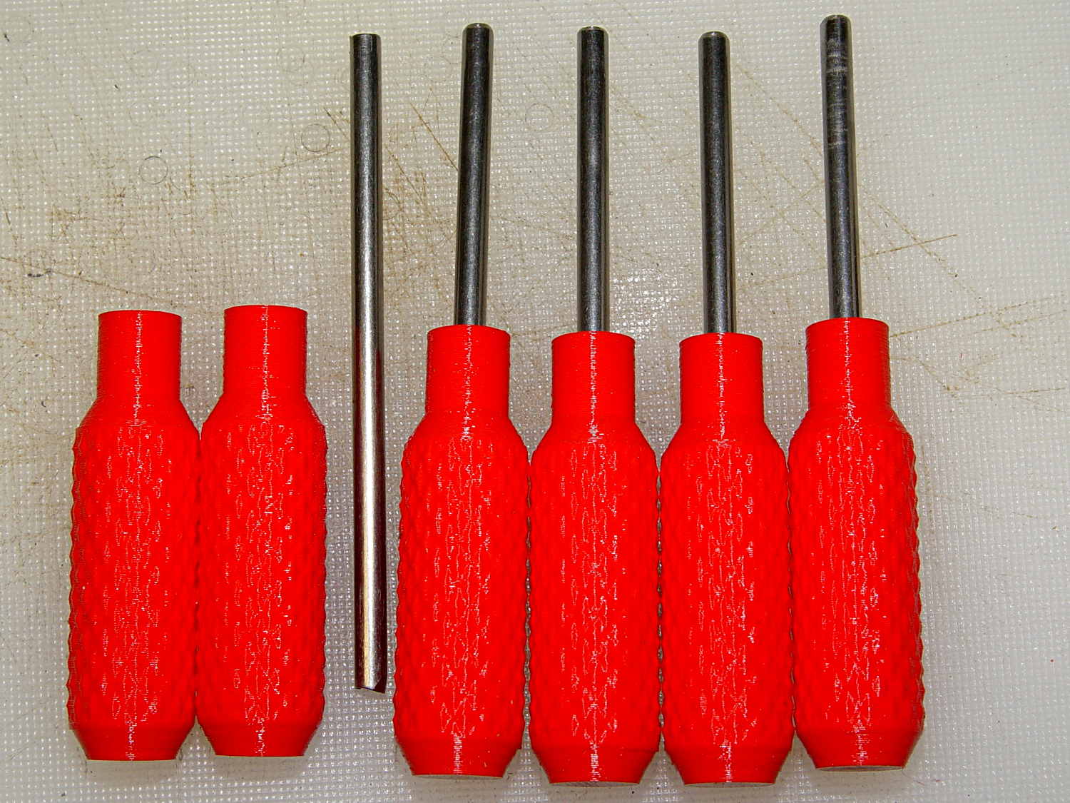
    Sherline Tommy Bar Handles
    Sherline Tommy Bar Handles

    A dab of urethane adhesive inside the handle holds the bar in place. They started out a snug slip fit, so we’ll see how well that holds the bars in place.

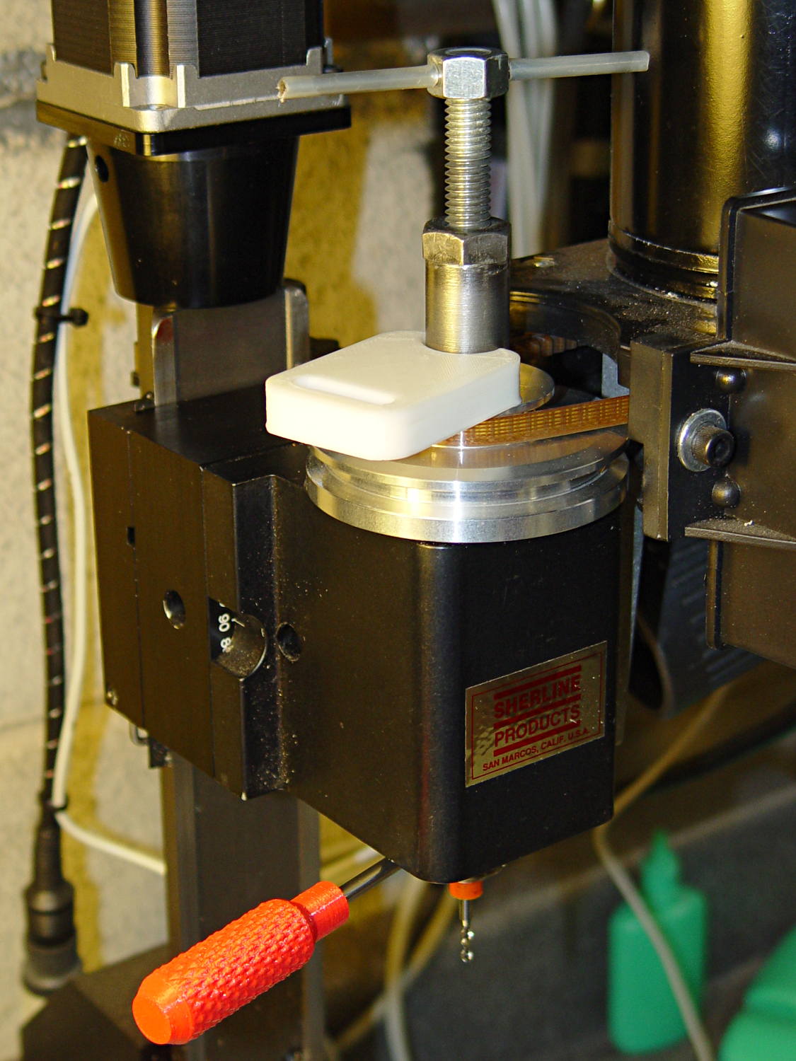
    A tommy bar holds the spindle against the torque from the collet pusher:
    Sherline CNC mill - tommy bar and collet pusher
    Sherline CNC mill – tommy bar and collet pusher

    A pair will come in handy with the three-jaw chuck the next time that one appears.

    The white slab is a very early 3D printed tool from my Thing-O-Matic, made to hold the pin at exactly the proper distance from the pulley so it fits squarely into the pusher and locks it to the spindle:

    Locking pin holder - spindle end view
    Locking pin holder – spindle end view

    Other folks make much nicer tommy bar handles than mine, but I’d say my 3D printed handles beat a common nail any day!

    The OpenSCAD source code:

    // Knurled handles for Sherline tommy bars
    // Ed Nisley - KE4ZNU - December 2013
    
    use <knurledFinishLib_v2.scad>
    
    //- Extrusion parameters must match reality!
    //  Print with 2 shells and 3 solid layers
    
    ThreadThick = 0.20;
    ThreadWidth = 0.40;
    
    HoleWindage = 0.2;			// extra clearance
    
    Protrusion = 0.1;			// make holes end cleanly
    
    PI = 3.14159265358979;
    inch = 25.4;
    
    //----------------------
    // Dimensions
    
    ShaftDia = 10.0;				// un-knurled section diameter
    ShaftLength = 10.0;				//  ... length
    
    SocketDia = 4.0;				// tommy bar diameter
    SocketDepth = 40.0;
    
    KnurlLen = 35.0;				// length of knurled section
    KnurlDia = 15.0;				//   ... diameter
    KnurlDPNom = 32;				// Nominal diametral pitch = (# diamonds) / (OD inches)
    
    DiamondDepth = 0.5;				//   ... depth of diamonds
    DiamondAspect = 2;				// length to width ratio
    
    NumDiamonds = floor(KnurlDPNom * KnurlDia / inch);
    echo(str("Num diamonds: ",NumDiamonds));
    
    NumSides = 4*(NumDiamonds - 1);		// 4 facets per diamond. Library computes diamonds separately!
    
    KnurlDP = NumDiamonds / (KnurlDia / inch);				// actual DP
    echo(str("DP Nom: ",KnurlDPNom," actual: ",KnurlDP));
    
    DiamondWidth = (KnurlDia * PI) / NumDiamonds;
    
    DiamondLenNom = DiamondAspect * DiamondWidth;					// nominal diamond length
    DiamondLength = KnurlLen / round(KnurlLen/DiamondLenNom);		//  ... actual
    
    TaperLength = 0.75*DiamondLength;
    
    //----------------------
    // Useful routines
    
    module PolyCyl(Dia,Height,ForceSides=0) {			// based on nophead's polyholes
    
      Sides = (ForceSides != 0) ? ForceSides : (ceil(Dia) + 2);
    
      FixDia = Dia / cos(180/Sides);
    
      cylinder(r=(FixDia + HoleWindage)/2,
               h=Height,
               $fn=Sides);
    }
    
    module ShowPegGrid(Space = 10.0,Size = 1.0) {
    
      Range = floor(50 / Space);
    
    	for (x=[-Range:Range])
    	  for (y=[-Range:Range])
    		translate([x*Space,y*Space,Size/2])
    		  %cube(Size,center=true);
    }
    
    //- Build it
    
    ShowPegGrid();
    
    difference() {
    	union() {
    		render(convexity=10)
    		translate([0,0,TaperLength])
    			knurl(k_cyl_hg=KnurlLen,
    				  k_cyl_od=KnurlDia,
    				  knurl_wd=DiamondWidth,
    				  knurl_hg=DiamondLength,
    				  knurl_dp=DiamondDepth,
    				  e_smooth=DiamondLength/2);
    		color("Orange")
    		cylinder(r1=ShaftDia/2,
    					r2=(KnurlDia - DiamondDepth)/2,
    					h=(TaperLength + Protrusion),
    					$fn=NumSides);
    		color("Orange")
    		translate([0,0,(TaperLength + KnurlLen - Protrusion)])
    			cylinder(r2=ShaftDia/2,
    					r1=(KnurlDia - DiamondDepth)/2,
    					h=(TaperLength + Protrusion),
    					$fn=NumSides);
    		color("Moccasin")
    		translate([0,0,(2*TaperLength + KnurlLen - Protrusion)])
    			cylinder(r=ShaftDia/2,h=(ShaftLength + Protrusion),$fn=NumSides);
    
    	}
    	translate([0,0,(2*TaperLength + KnurlLen + ShaftLength - SocketDepth + Protrusion)])
    		PolyCyl(SocketDia,(SocketDepth + Protrusion),6);
    }
    
  • Sherline Four-Jaw Chuck Speed Wrenches: 3D Printed Edition

    A Home Shop Machinist article (A Speed Key for Your Four-Jaw Chuck, p 67 Nov-Dec 2013, David Morrow) showed some lovely knurled steel knobs. These 3D printed knobs aren’t nearly as pretty, but they do much the same thing:

    Sherline Knobs - in 4 jaw chuck
    Sherline Knobs – in 4 jaw chuck

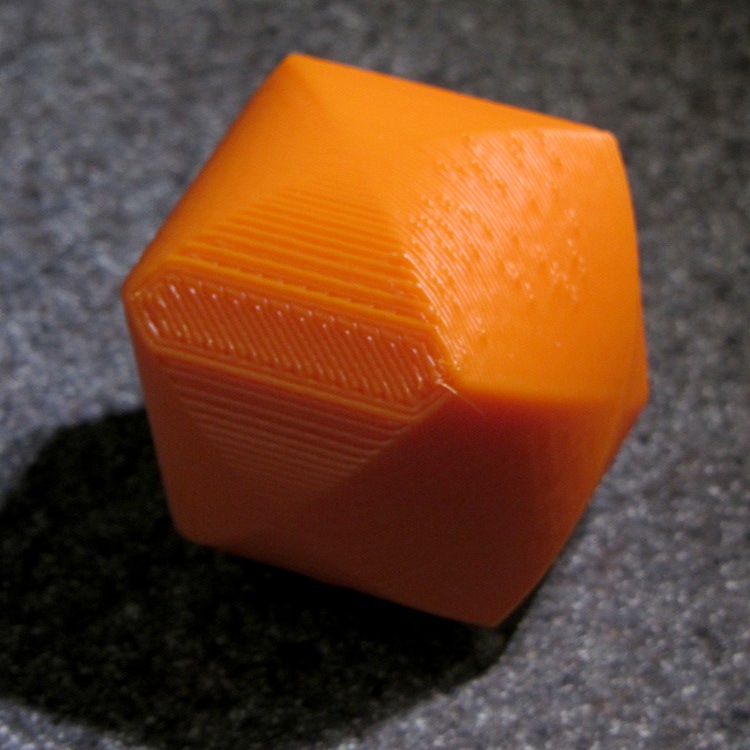
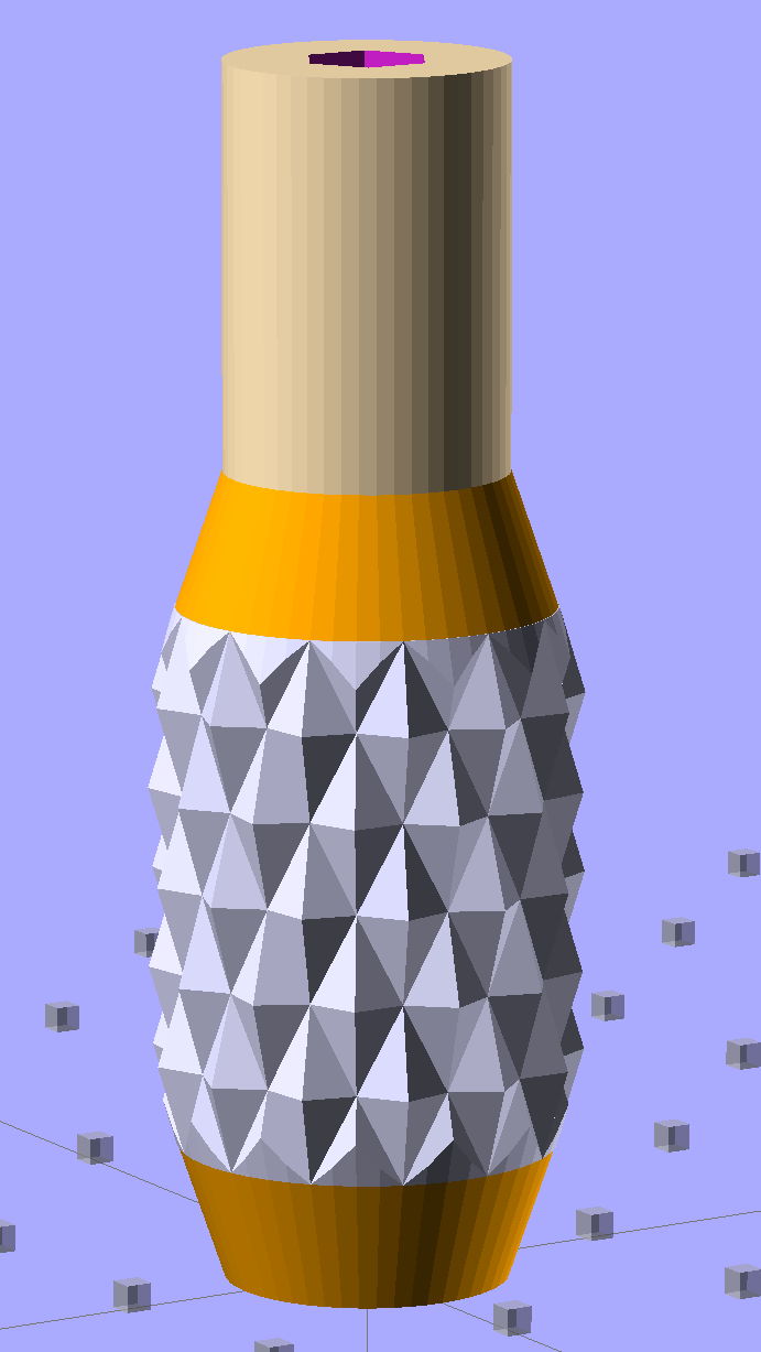
    The solid model resembles the illegitimate offspring of a wine bottle and a pineapple:

    Sherline Knob - solid model
    Sherline Knob – solid model

    The knurling comes from aubenc’s Knurled Surface Library v2. I ran off a prototype (on the left), then tweaked the dimensions to get the final version on the right:

    Sherline Knobs - knurl depth variation
    Sherline Knobs – knurl depth variation

    Being that type of guy, I define the knurl in terms of its diametral pitch, compute the diamond width & length to fit in the available space, then hand those measurements to the knurling library… which recomputes everything and decides on one less diamond than I do: NumSides has a Finagle Constant of -1 to make the answer come out right. We may be using a different diameter or something, but I haven’t deciphered the source code. It’s parametric out the wazoo, as usual, so you can spin up what you like, how you like it.

    Anyhow, a 24 DP knurl with 1.0 mm depth looks and feels pretty good; the XY resolution isn’t good enough for a 48 DP knurl around that knob diameter. The diamonds don’t come out as crisp and pointy as crushed steel knurls, but they’re OK for my fingers.

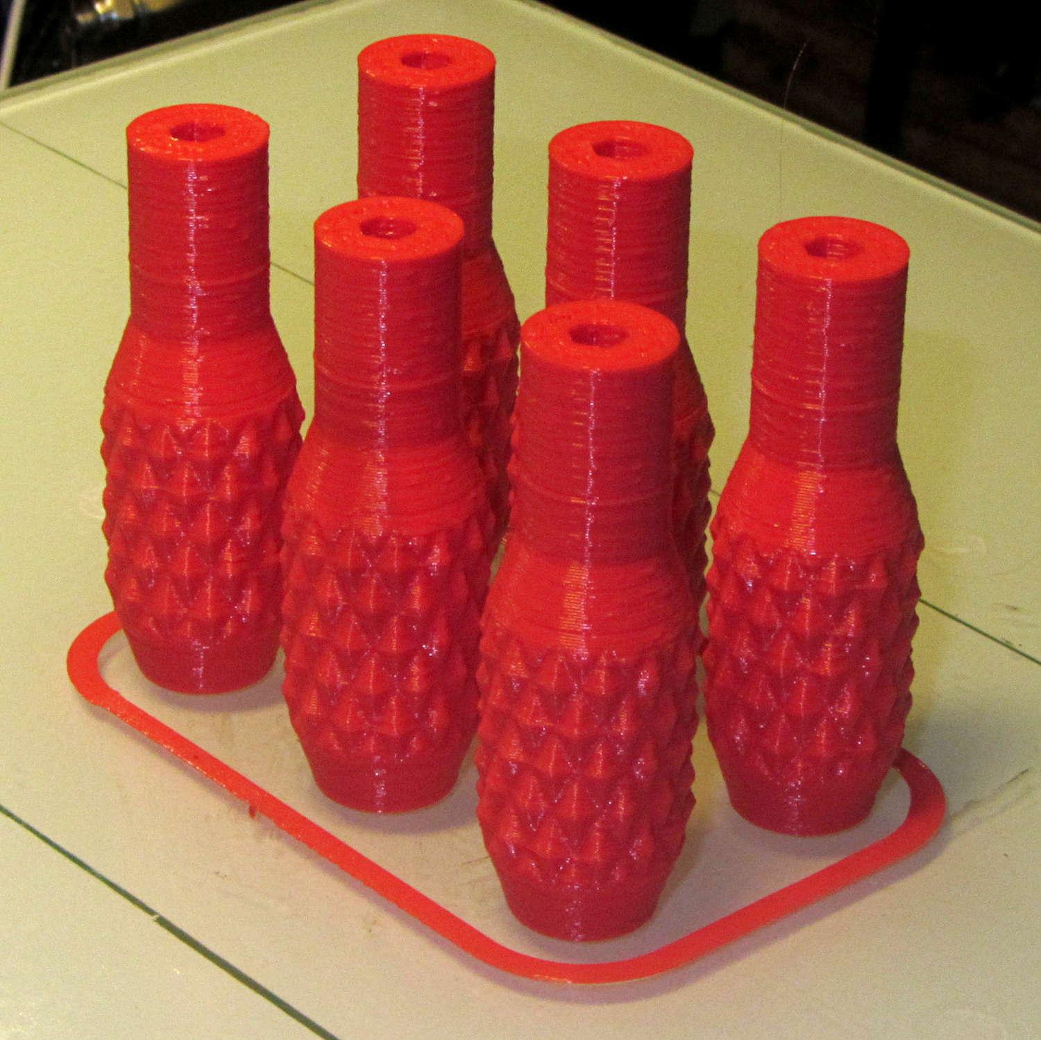
    Doing half a dozen doesn’t take much longer than doing a few, because there’s a 20 second minimum layer time in effect and those things don’t have much plastic, so now I have one for the hold-down clamps and another for Show-n-Tell sessions:

    Sherline Knobs - M2 platform
    Sherline Knobs – M2 platform

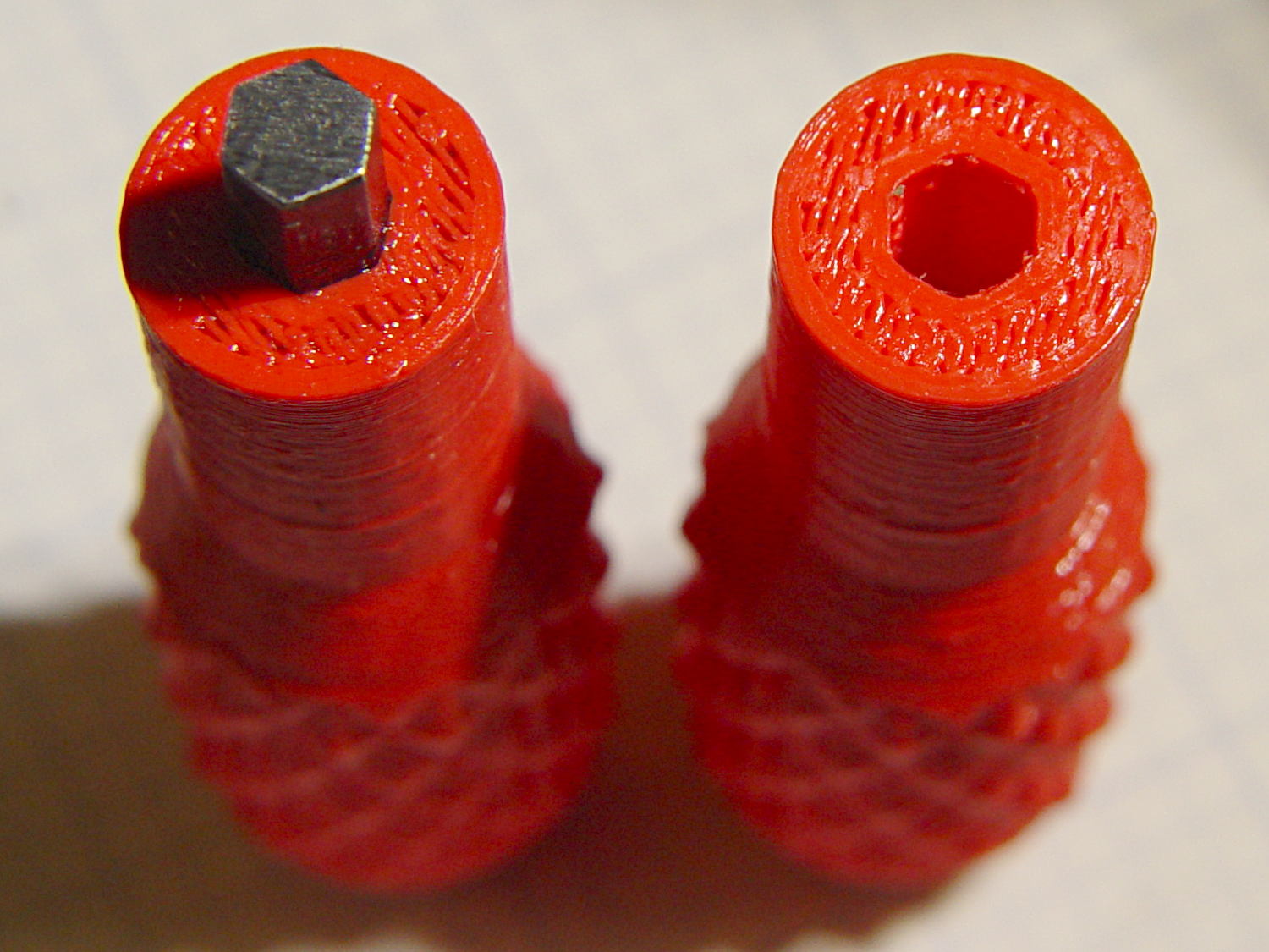
    I chopped a 5/32 inch hex key into five 15 mm lengths with a Dremel cutoff wheel, then filed both ends flat and broke the edges. The hex stubs were a press fit in the hex holes, so I finger-started them, grabbed the hex in the drill press, aligned the handle below, and rammed the stub about 5 mm deep. The final depth comes from jamming the wrench into the chuck and pressing firmly, so the stubs project exactly as far as possible:

    Sherline Knobs - hex key inserted
    Sherline Knobs – hex key inserted

    One might quibble about the infill on the end; one may go adjust one’s own printer as one prefers.

    There’s 0.1 mm more HoleWindage than usual, because these holes must fix a hex shaft, not a circular pin, and the corners need some clearance. They came out a firm press fit: exactly what’s needed.

    They’re no good for final tightening of those chuck jaws, but that’s not their purpose…

    The OpenSCAD source code:

    // Knurled handles for Sherline hex keys
    // Ed Nisley - KE4ZNU - November 2013
    
    use <knurledFinishLib_v2.scad>
    
    //- Extrusion parameters must match reality!
    //  Print with 2 shells and 3 solid layers
    
    ThreadThick = 0.20;
    ThreadWidth = 0.40;
    
    HoleWindage = 0.3;			// extra clearance to improve hex socket fit
    
    Protrusion = 0.1;			// make holes end cleanly
    
    PI = 3.14159265358979;
    inch = 25.4;
    
    //----------------------
    // Dimensions
    
    ShaftDia = 10.5;				// un-knurled section diameter
    ShaftLength = 15.0;				//  ... length
    
    SocketDia = (5/32) * inch;		// hex key size
    SocketDepth = 10.0;
    
    KnurlLen = 20.0;				// length of knurled section
    KnurlDia = 15.0;				//   ... diameter
    KnurlDPNom = 24;				// Nominal diametral pitch = (# diamonds) / (OD inches)
    
    DiamondDepth = 1.0;				//   ... depth of diamonds
    DiamondAspect = 2;				// length to width ratio
    
    NumDiamonds = floor(KnurlDPNom * KnurlDia / inch);
    echo(str("Num diamonds: ",NumDiamonds));
    
    NumSides = 4*(NumDiamonds - 1);		// 4 facets per diamond. Library computes diamonds separately!
    
    KnurlDP = NumDiamonds / (KnurlDia / inch);				// actual DP
    echo(str("DP Nom: ",KnurlDPNom," actual: ",KnurlDP));
    
    DiamondWidth = (KnurlDia * PI) / NumDiamonds;
    
    DiamondLenNom = DiamondAspect * DiamondWidth;					// nominal diamond length
    DiamondLength = KnurlLen / round(KnurlLen/DiamondLenNom);		//  ... actual
    
    TaperLength = 0.75*DiamondLength;
    
    //----------------------
    // Useful routines
    
    module PolyCyl(Dia,Height,ForceSides=0) {			// based on nophead's polyholes
    
      Sides = (ForceSides != 0) ? ForceSides : (ceil(Dia) + 2);
    
      FixDia = Dia / cos(180/Sides);
    
      cylinder(r=(FixDia + HoleWindage)/2,
               h=Height,
    	   $fn=Sides);
    }
    
    module ShowPegGrid(Space = 10.0,Size = 1.0) {
    
      Range = floor(50 / Space);
    
    	for (x=[-Range:Range])
    	  for (y=[-Range:Range])
    		translate([x*Space,y*Space,Size/2])
    		  %cube(Size,center=true);
    }
    
    //- Build it
    
    ShowPegGrid();
    
    difference() {
    	union() {
    		render(convexity=10)
    		translate([0,0,TaperLength])
    			knurl(k_cyl_hg=KnurlLen,
    				  k_cyl_od=KnurlDia,
    				  knurl_wd=DiamondWidth,
    				  knurl_hg=DiamondLength,
    				  knurl_dp=DiamondDepth,
    				  e_smooth=DiamondLength/2);
    		color("Orange")
    		cylinder(r1=ShaftDia/2,
    					r2=(KnurlDia - DiamondDepth)/2,
    					h=(TaperLength + Protrusion),
    					$fn=NumSides);
    		color("Orange")
    		translate([0,0,(TaperLength + KnurlLen - Protrusion)])
    			cylinder(r2=ShaftDia/2,
    					r1=(KnurlDia - DiamondDepth)/2,
    					h=(TaperLength + Protrusion),
    					$fn=NumSides);
    		color("Moccasin")
    		translate([0,0,(2*TaperLength + KnurlLen - Protrusion)])
    			cylinder(r=ShaftDia/2,h=(ShaftLength + Protrusion),$fn=NumSides);
    
    	}
    	translate([0,0,(2*TaperLength + KnurlLen + ShaftLength - SocketDepth + Protrusion)])
    		PolyCyl(SocketDia,(SocketDepth + Protrusion),6);
    }
    

    This might be a good stocking stuffer for that guy who has everything, but you’d need his shop to make it, so what’s the point in that?

  • Browning Hi-Power Magazine: Nut Trap Block Trial

    The general idea is to reduce the capacity of a 13 round Browning Hi-Power magazine to 10 rounds, in compliance with the NY Safe Act, using a number of possibly invalid assumptions. The new Firearms tag will produce earlier posts.

    This early prototype tried out the sizes, shapes, and angles, using an M3x0.5 socket head cap screw:

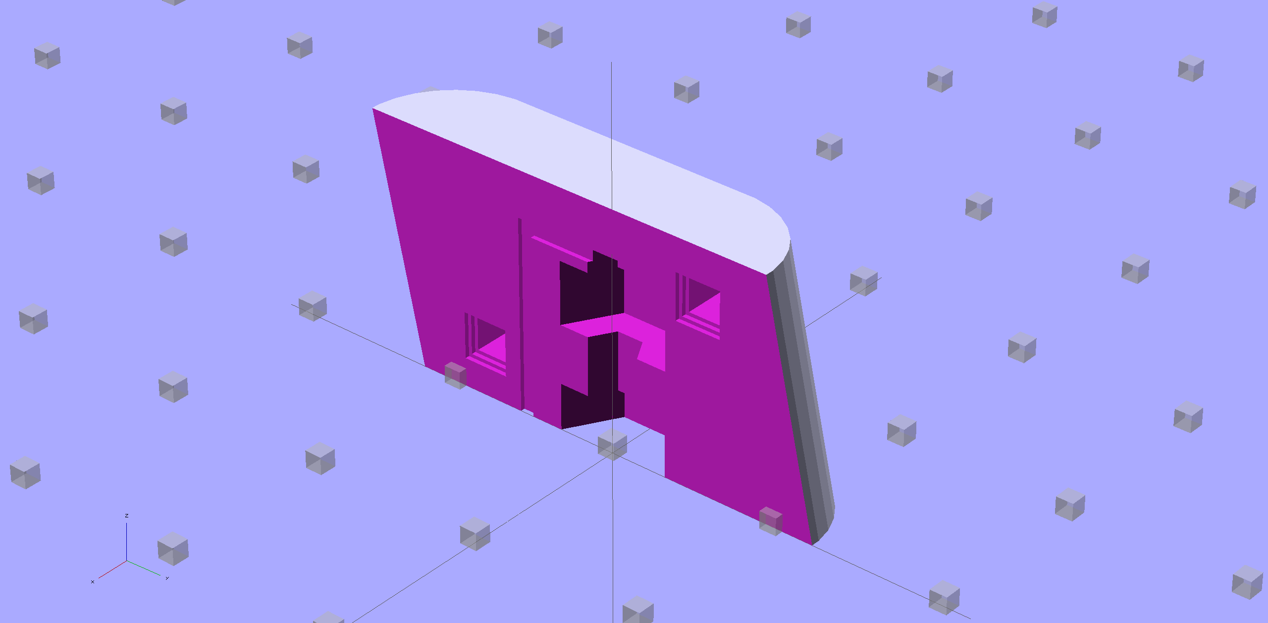
    Browning Hi-Power Magazine Block - solid model - nut trap prototype
    Browning Hi-Power Magazine Block – solid model – nut trap prototype

    The bottom nut trap locates the block on the inner floor plate by capturing the nut. It might need a bit more clearance or a chamfer to allow for brazing material around the nut flats; cleaning up the brazed nut with a file might also help.

    The central trap holds a nut that anchors the block; the trap must be about 50% longer than the nut to allow for thread alignment, because the central hole is a loose tap fit.

    That central nut probably isn’t needed, because you’d fill the central shaft with metal-loaded epoxy, which would form a perfectly serviceable, exactly form-fitting, and utterly non-removable “nut”. The vent from the end of the screw shaft releases air trapped behind the epoxy by the screw; if you don’t have a vent, then air pressure will force the epoxy out of the cavity.

    If the epoxy “nut” is workable, then you can build it in a single piece printed vertically on the platform. Having a split version makes it easier to show off and, in truth, the cemented joint is about as strong as the rest of the object.

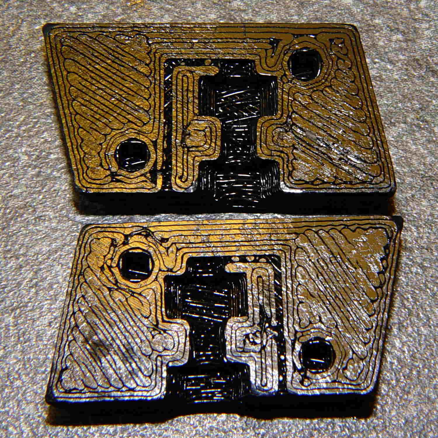
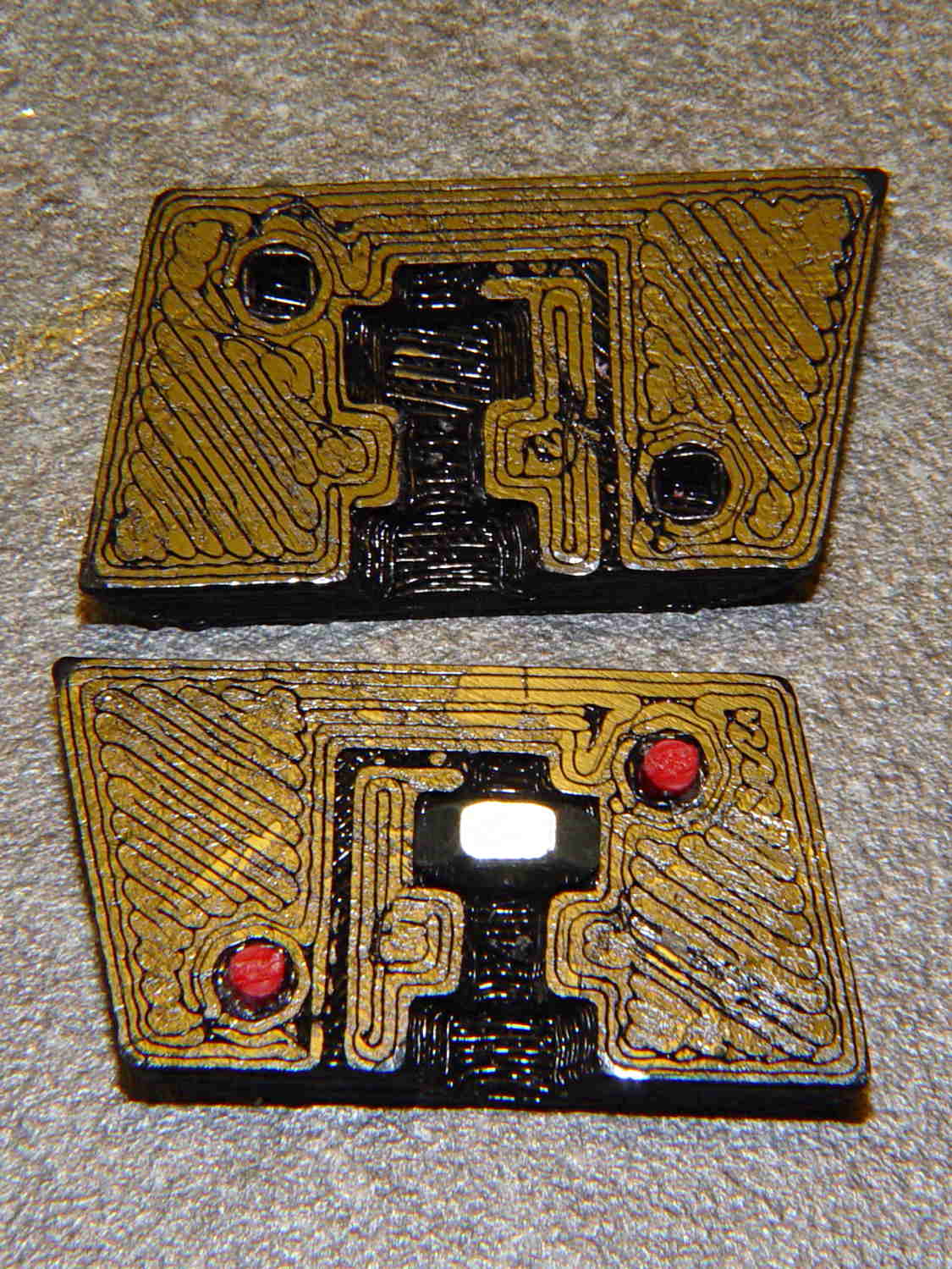
    Hot off the M2 3D printer, it looks like this:

    BHP magazine block - prototype nut trap - bare
    BHP magazine block – prototype nut trap – bare

    A few threads droop into the air vent, so that channel should be larger. The overall plastic block may be porous enough to release the air pressure even without a vent.

    With locating pins glued in place and a nut in the central trap:

    BHP magazine block - prototype nut trap
    BHP magazine block – prototype nut trap

    Pretty much as I expected, it doesn’t quite fit in the magazine, because it doesn’t have clearance for the little tab on the inner floor plate that captures the spring.

    One might argue that a plastic block isn’t “permanent”, but it’s definitely not “readily” removed:

    • PLA doesn’t dissolve in common solvents
    • It doesn’t actually melt and flow away at high temperatures
    • It’s protected by the spring and inner floor plate
    • It’s certainly strong enough to resist simple mechanical attacks

    This is a start…

    The OpenSCAD source code, replete with inadequacies:

    // Browning Hi-Power Magazine Plug
    // Ed Nisley KE4ZNU November 2013
    
    Layout = "Show";			// Show Whole Pin Build
    
    CrossSection = 1;			// -1, 0, 1 to select section side or none
    
    Section = (Layout == "Build") ? 1 : CrossSection;		// for cross-section for build
    
    //- Extrusion parameters must match reality!
    //  Print with 2 shells and 3 solid layers
    
    ThreadThick = 0.25;
    ThreadWidth = 0.40;
    
    HoleWindage = 0.2;
    
    Protrusion = 0.1;			// make holes end cleanly
    
    //----------------------
    // Dimensions
    
    Angle = 12.5;				// from vertical
    
    EndDia = 10.3;				// an 11/32 inch drill fits
    EndRadius = EndDia / 2;
    
    Length = 24.0;				// front-to-back perpendicular to magazine shaft
    Height = 14.0;				// bottom-to-top, parallel to magazine shaft
    							//  14 = 10 round capacity
    							//  28 = 7 round
    
    RectLength = Length - EndDia;	// block length between end radii
    
    ScrewOD = 3.0 - 0.5;		// bottom screw tapping diameter
    ScrewLength = 11.0;
    ScrewOffset = 0;			//   ... from centerline
    
    NutOD = 5.5;				// hex nut dia across flats
    NutThick = 2.4;				//  ... then add 50% for thread engagement & epoxy
    NutOffset = 6.0;			//  ... base height from floor
    
    VentWidth = 2*ThreadWidth;	// air vent from back of screw recess
    VentDepth = 4*ThreadThick;
    
    NumSides = 8*4;				// default cylinder sides
    
    PinOD = 1.72;				// alignment pins
    PinLength = 6.0;
    PinInset = 0.9*EndRadius;	// from outside edges
    echo(str("Alignment pin length: ",PinLength));
    
    Offset = 5.0/2;				// from centerline for build layout
    
    //----------------------
    // Useful routines
    
    // Locating pin hole with glue recess
    //  Default length is two pin diameters on each side of the split
    
    module LocatingPin(Dia=PinOD,Len=0.0) {
    
    	PinLen = (Len != 0.0) ? Len : (4*Dia);
    
    	translate([0,0,-ThreadThick])
    		PolyCyl((Dia + 2*ThreadWidth),2*ThreadThick,4);
    
    	translate([0,0,-2*ThreadThick])
    		PolyCyl((Dia + 1*ThreadWidth),4*ThreadThick,4);
    
    	translate([0,0,-(Len/2 + ThreadThick)])
    		PolyCyl(Dia,(Len + 2*ThreadThick),4);
    
    }
    
    module PolyCyl(Dia,Height,ForceSides=0) {			// based on nophead's polyholes
    
      Sides = (ForceSides != 0) ? ForceSides : (ceil(Dia) + 2);
    
      FixDia = Dia / cos(180/Sides);
    
      cylinder(r=(FixDia + HoleWindage)/2,
               h=Height,
    	   $fn=Sides);
    }
    
    module ShowPegGrid(Space = 10.0,Size = 1.0) {
    
      Range = floor(50 / Space);
    
    	for (x=[-Range:Range])
    	  for (y=[-Range:Range])
    		translate([x*Space,y*Space,Size/2])
    		  %cube(Size,center=true);
    
    }
    
    //----------------------
    // Components
    
    module Block(SectionSelect = 0) {
    
    Delta = tan(Angle)*(Length/2);				// incremental length due to angle
    
    CropHeight = Height*cos(Angle);				// block height perpendicular to base
    
    echo(str("Perpendicular height: ",CropHeight));
    
    	difference() {
    		intersection() {
    			rotate([Angle,0,0])
    				difference() {
    					translate([0,0,-Height/2])
    						linear_extrude(height=2*Height,convexity=2) {
    							for (i=[-1,1])
    								translate([0,(i*RectLength/2),0])
    									rotate(180/NumSides)
    										circle(r=EndRadius/cos(180/NumSides),
    												$fn=NumSides);
    							square([EndDia,RectLength],center=true);
    						}
    					for (i=[-1,1])
    						translate([0,
    									(i*(Length/2 - PinInset)),
    									(CropHeight/2 + i*(CropHeight/2 - PinInset))])
    							rotate([0,90,0]) rotate(45-Angle)
    								LocatingPin(PinOD,PinLength);
    				}
    			translate([0,0,CropHeight/2])
    				cube([2*EndDia,3*Length,CropHeight],center=true);
    		}
    		translate([0,ScrewOffset,-Protrusion])		// screw
    			rotate(180/6)
    				PolyCyl(ScrewOD,(ScrewLength + Protrusion),6);
    
    		translate([0,ScrewOffset,NutOffset])		// nut trap in center
    			rotate(180/6)
    				PolyCyl(NutOD,1.5*NutThick,6);
    
    		translate([0,ScrewOffset,-Protrusion])		// nut clearance at base
    			rotate(180/6)
    				PolyCyl(NutOD,(1.1*NutThick + Protrusion),6);
    
    		translate([0,-(ScrewOffset + NutOD),(ScrewLength - Protrusion)/2])	// air vent
    			cube([VentDepth/2,VentWidth,(ScrewLength + Protrusion)],center=true);
    		translate([0,(ScrewOffset - NutOD/2),(ScrewLength - VentWidth/2)])
    			cube([VentDepth/2,NutOD,VentWidth],center=true);
    
    		if (SectionSelect == 1)
    			translate([EndDia,0,Height/2-Protrusion])
    				cube([2*EndDia,3*Length,Height+2*Protrusion],center=true);
    		else if (SectionSelect == -1)
    			translate([-EndDia,0,Height/2-Protrusion])
    				cube([2*EndDia,3*Length,Height+2*Protrusion],center=true);
    	}
    
    }
    
    //-------------------
    // Build it...
    
    ShowPegGrid();
    
    if (Layout == "Pin")
    	LocatingPin(PinOD,PinLength);
    
    if (Layout == "Show")
    	Block(CrossSection);
    
    if (Layout == "Whole")
    	Block(0);
    
    if (Layout ==  "Build") {
    	translate([(Offset + Length/2),Height/2,0])
    		rotate(90) rotate([0,-90,-Angle])
    			Block(-1);
    	translate([-(Offset + Length/2),Height/2,0])
    		rotate(-90) rotate([0,90,Angle])
    			Block(1);
    }
    
  • Browning Hi-Power Magazine: Trigonometry

    The Browning Hi-Power magazine case has a 12.5° forward angle with respect to the floor plates:

    Browning Hi-Power magazine - components
    Browning Hi-Power magazine – components

    The natural axes lie parallel and perpendicular to the case axis, which means dimensions parallel and perpendicular to the floor plates (horizontal & vertical, respectively) require a bit of trigonometry. This doodle sketches some of the key values, not all of which are hereby asserted to be correct:

    Magazine angle doodles
    Magazine angle doodles

    Name the variables:

    • Slant angle α
    • Height H along magazine axis
    • Length L perpendicular to H

    Components of H:

    • vertical = H cos α
    • horizontal = H sin α

    Components of L:

    • vertical = L sin α
    • horizontal = L cos α

    Extreme point of the tilt at the edge, relative to center point on axis:

    • vertical = (L/2) sin α
    • horizontal= (L/2) cos α

    Projection of top parallel to axis onto horizontal:

    • L / cos α

    I suppose one could set up functions for all that, but I tend to just hammer out the trig where it’s needed.

  • Dummy 9 mm Luger Cartridge: 100 μm Layers

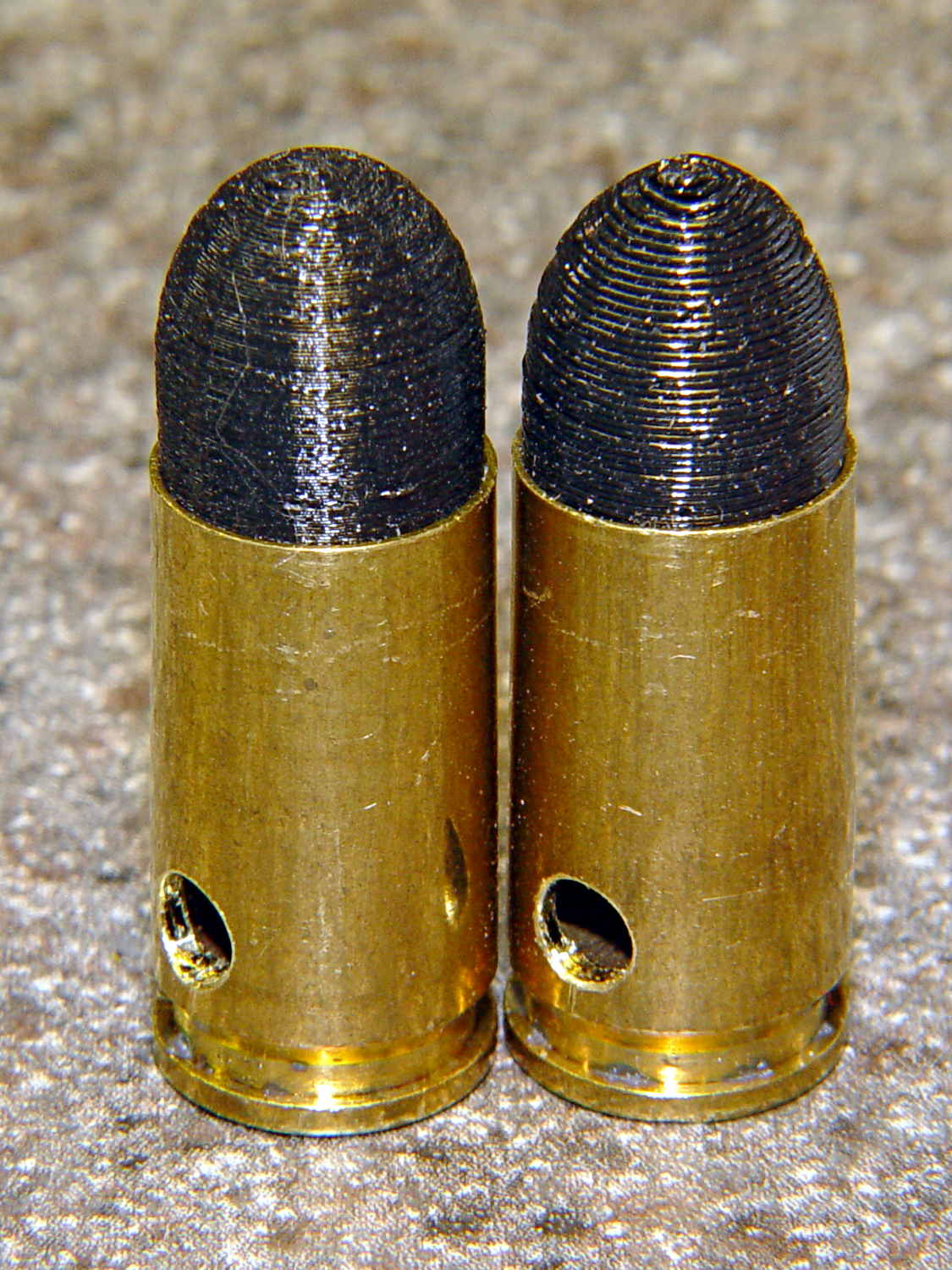
    As you might expect, changing the layer thickness to 0.1 mm = 100 μm dramatically improves the appearance of the dummy 9 mm Luger bullet on the left, compared to the 0.25 mm = 250 μm layers on the right:

    Dummy 9 mm Luger cartridges - 0.1 mm layer - overview
    Dummy 9 mm Luger cartridges – 0.1 mm layer – overview

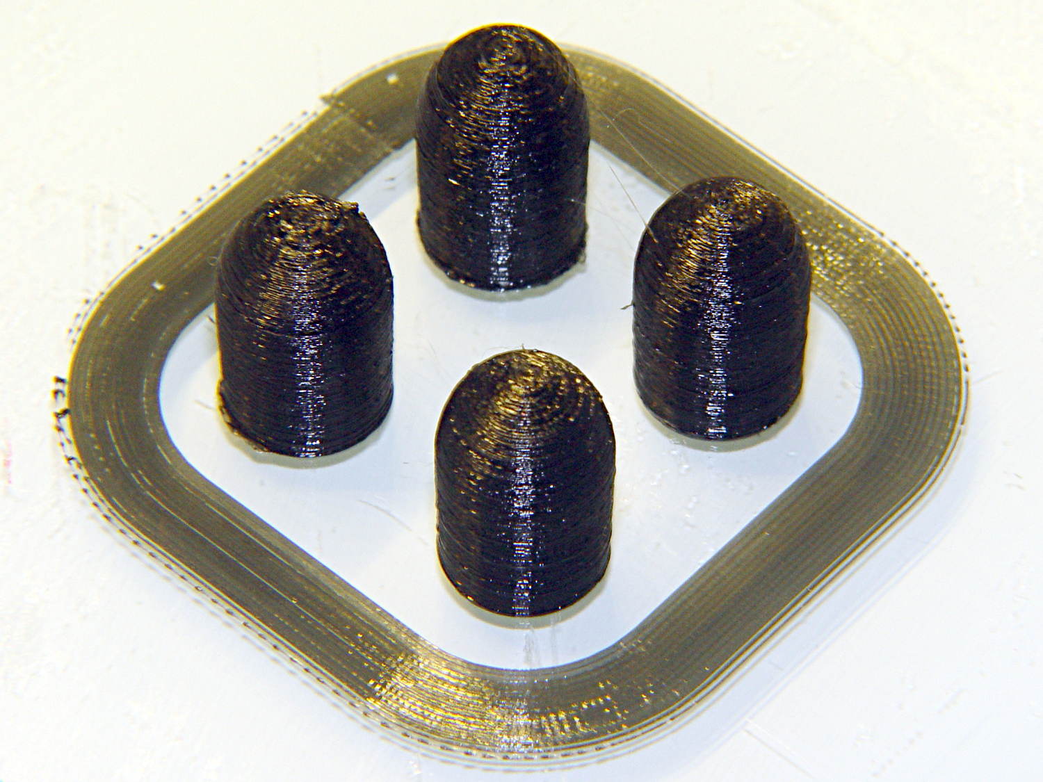
    The inside edge of the translucent skirt around the quartet measured 90 to 110 μm, so the layer height is spot on:

    Dummy 9 mm Luger bullets - 0.1 mm layer - overhead on platform
    Dummy 9 mm Luger bullets – 0.1 mm layer – overhead on platform

    That required no adjustments to the M2 at all; It Just Works. Admittedly, that’s with a custom platform and firm supports replacing the springs, plus better Z-axis homing, but the overall structure was fine to start with.

    I used the same Slic3r settings as before, with the only change being the layer thickness. Letting it pick the layer width might produce better results, but a 0.35 mm nozzle won’t go much narrower than 0.40 mm anyway.

    A closer look at the bullet show the thinner layers provide a better rendition of the stretched sphere forming the nose; it’s less pointy than the one assembled from thicker layers:

    Dummy 9 mm Luger bullets - 0.1 mm layer - side
    Dummy 9 mm Luger bullets – 0.1 mm layer – side

    The nose closes better with thinner layers:

    Dummy 9 mm Luger bullets - 0.1 mm layer - nose
    Dummy 9 mm Luger bullets – 0.1 mm layer – nose

    None of that really matters for this application, but it’s a useful data point.

    The downside is that printing with thinner layers requires more time: a single bullet (of 16) requires 2.2 minutes at 250 μm and (of 4) 9 minutes at 100 μm. The simple ratio of layer thicknesses predicts a factor of 2.5, not 4, but the skirt requires a larger fraction of the total time. The estimated time for a 4×4 array at 100 μm comes out at 5.2 minutes each, a factor of 2.4, which is close enough.

    Although 100 μm certainly looks better, it doesn’t really improve anything for most of the blocky stuff I make…

  • Dummy 9 mm Luger Cartridge

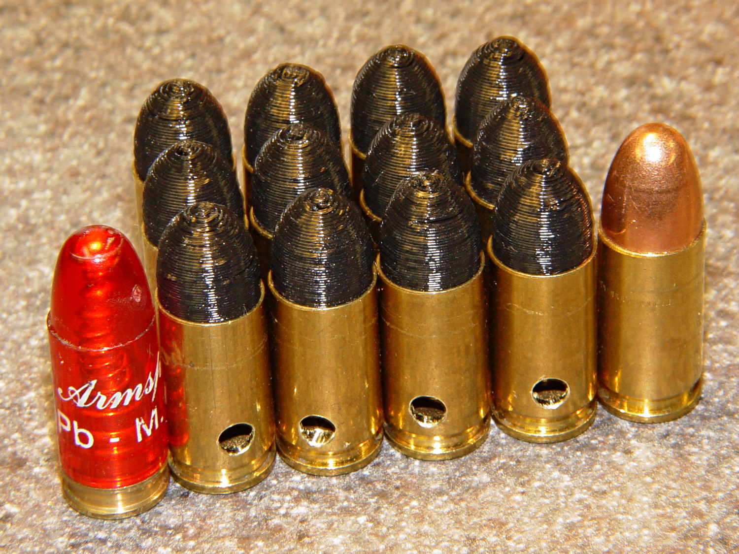
    An interesting project requires a handful of 9 mm Luger (aka 9 mm NATO) dummy cartridges with real brass. You can buy exact form / fit / weight dummies or plastic training rounds, but these will suit my simple needs:

    Dummy 9 mm Luger cartridges
    Dummy 9 mm Luger cartridges

    That’s a snap cap on the left and a real 9 mm Luger cartridge on the right. The holes in the dummy brass indicate that they are absolutely, positively, unquestionably not loaded cartridges.

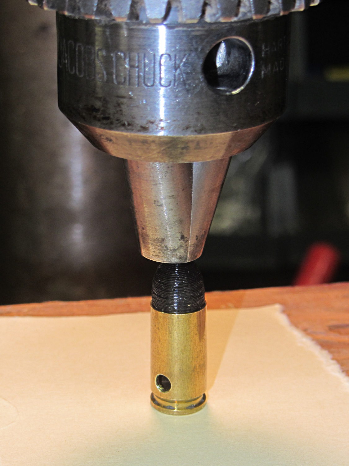
    Start by drilling a 1/8 inch hole in the side of each unfired, primerless case:

    Dummy 9 mm Luger - drilling case
    Dummy 9 mm Luger – drilling case

    I set up the chuck on the rotary table, thinking I might drill three holes in each cartridge, but came to my senses. It’s lined up by eye, flush with the end of the jaws, and the hole is just above the inside of the base.

    The solid model has the same overall length and proportion as a 115 grain FMJ bullet, but doesn’t match the proper ogive or base diameter. Basically, I stretched a 9 mm sphere and stuck it atop a slightly tapered base cylinder:

    Dummy 9 mm Luger bullet - solid model
    Dummy 9 mm Luger bullet – solid model

    For reasons I don’t profess to understand, the sphere has a slightly different diameter at its equator than the top of the cylinder, even though they’re both the same BulletOD diameter with the same number of faces. Fortunately, that didn’t affect the final results.

    Print up a handful of the things:

    Dummy 9 mm Luger bullets - on platform
    Dummy 9 mm Luger bullets – on platform

    The shadow from the flash makes the bases look slightly fatter than they really are.

    Using a thinner layer would look better in this orientation. They’d definitely look better if they were split, printed with the long axis parallel to the plate, and glued together, as the grain would run lengthwise; I’m not sure there’s enough room for alignment pins, though.

    At this diameter and number of faces, the M2 produces almost perfectly accurate dimensions, so the bullets press-fit just like you’d expect. They’re twisted into a dab of urethane glue inside the brass that foams just enough to hold them place.

    Rather than use a real seating die, I deployed a closed chuck on the drill press. The trick is to set the depth stop to produce slightly too-long cartridges, then shim the platform without changing the stop and seat the bullet to the proper depth:

    Dummy 9 mm Luger - seating bullet
    Dummy 9 mm Luger – seating bullet

    The OAL tolerance for various 9 mm Luger cartridges seems to range from 1.08 inch to 1.17 inch, so anything in that range should be fine. I used 1.10 inch.

    These are not intended for firing. You could fire them with just a primer (in a non-drilled case) and (maybe) not melt or shatter the plastic, but they’re slightly larger than the nominal 8.82 mm land diameter and won’t obturate or spin-stabilize worth diddly: expect short range and keyholing.

    The sectional density is a whopping 0.008, should you keep track of such things: 0.47 gram = 7.2 grain. Note that the US small arms definition of sectional density has units of pound/inch2, not the pound/foot2 you’ll find right next to values computed using inches; the magic number 1/7000 just converts from grains to pounds. In the rest of the (metric) world, it’s entirely different.

    The OpenSCAD source code:

    // Dummy 9mm Luger bullet
    // Ed Nisley KE4ZNU November 2013
    
    //----------------------
    // Dimensions
    
    BulletOD = 9.05;			// main diameter
    BulletBaseOD = 8.8;			//  ... easy insertion
    
    BulletOAL = 14.0;			// overall length
    BaseLength = 8.0;			// cylindrical base length
    
    NoseLength = BulletOAL - BaseLength;
    
    NumSides = 8*4;
    
    //----------------------
    // Useful routines
    
    module ShowPegGrid(Space = 10.0,Size = 1.0) {
    
      Range = floor(50 / Space);
    
    	for (x=[-Range:Range])
    	  for (y=[-Range:Range])
    		translate([x*Space,y*Space,Size/2])
    		  %cube(Size,center=true);
    }
    
    //-------------------
    // Build it...
    
    ShowPegGrid();
    
    color("Orange")
    cylinder(r1=BulletBaseOD/2,r2=BulletOD/2,h=BaseLength,$fn=NumSides);
    
    color("DarkOrange")
    translate([0,0,BaseLength])
    	resize([0,0,2*NoseLength])
    		sphere(BulletOD/2,$fn=NumSides);
    
  • Improved Alignment Pin Hole for Split 3D Prints

    I’ve been working on an object (more on this later) that requires precise alignment of two parts that capture a nut deep inside. This calls for alignment pins, similar to the ones I used for, say, the Triple-Cylinder Thing:

    Cylinder Thing - rotated
    Cylinder Thing – rotated

    The general idea is to design holes that fit the pins, then locate them at the parting line of the model, where they’re subtracted from the solid and appear in exactly the proper places when the model splits for printing:

    Cylinder Thing - alignment pegs
    Cylinder Thing – alignment pegs

    You slather solvent glue on both halves, jam pins into the holes, slap the parts together, and clamp until cured. Works fine, I use pins all over the place.

    The gotcha of using just a (polygonal) cylinder as the hole: if you glue one end of the pin at a time, a small rim of dissolved plastic may form around the pin at the surface. That can bond the two halves together or prevent them from joining properly after being disassembled.

    Sooo, here’s a new alignment pin hole with a gutter around the pin on both surfaces to capture the glop:

    Alignment pin hole - overview
    Alignment pin hole – overview

    Remember, that’s the negative volume that will hold the pin, not the pin itself!

    Here’s how it works in real plastic, with a 1.75 mm peg glued into one hole with a bit of crud in the gutter:

    Alignment Hole and Pin
    Alignment Hole and Pin

    The secret to making the gutter work: offset the second layer by half the thread width, so that it’s reasonably well supported on the first layer. If you don’t do that, the inner layers simply drop down through the hole and fill the gutter. Even doing that, notice the distortion of the first few layers inside the hole.

    The OpenSCAD source code looks about like you’d expect:

    //-- Locating pin hole with glue recess
    
    module LocatingPin(Dia=PinOD,Len=5.00) {
    
    	translate([0,0,-ThreadThick])
    		PolyCyl((Dia + 2*ThreadWidth),2*ThreadThick,4);
    
    	translate([0,0,-2*ThreadThick])
    		PolyCyl((Dia + 1*ThreadWidth),4*ThreadThick,4);
    
    	translate([0,0,-(Len/2 + ThreadThick)])
    		PolyCyl(Dia,(Len + 2*ThreadThick),4);
    }
    

    Ideally, the pin length should extend at least two diameters into each side of the object, but you can feed in whatever you need to make it come out right.

    The PolyCyl() routine produces a low-vertex-count polygon that circumscribes the nominal diameter, which is what you need for vertical holes in 3D printed objects:

    module PolyCyl(Dia,Height,ForceSides=0) {			// based on nophead's polyholes
    
      Sides = (ForceSides != 0) ? ForceSides : (ceil(Dia) + 2);
    
      FixDia = Dia / cos(180/Sides);
    
      cylinder(r=(FixDia + HoleWindage)/2,
               h=Height,
    	   $fn=Sides);
    }
    

    Tip o’ the cycling helmet to nophead for figuring out the polyhole idea and explaining why they’re needed…