Ed Nisley's Blog: Shop notes, electronics, firmware, machinery, 3D printing, laser cuttery, and curiosities. Contents: 100% human thinking, 0% AI slop.
This is a classic case of investing more time and effort creating the fixture than machining the parts.
Start by squaring up the block, which came from the end of a random chunk of smoke gray polycarbonate, with two 10-32 holes matching the tooling plate hole spacing:
Corner Clip Fixture – squaring
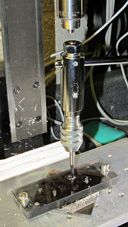
Then drill-and-tap four holes:
Corner Clip Fixture – tapping
The left station will be for drilling the blanks clamped under a sacrificial sheet, so those screw holes aren’t used for anything other than clearance; the top millimeter will get chewed up pretty quickly. The screws in the right station will clamp a stack of drilled blanks under a cover plate. If I went into production, I could see using both stations for both functions, but …
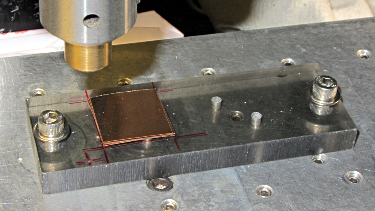
There’s a locating pip in the front left corner that works perfectly with laser alignment:
Corner Clip Fixture – aligning
The blank sheets show where they’d be located for drilling, minus the sacrificial sheet and its clamps that you’ll see below.
The G54 coordinate system origin sits at the locating pip. The G-Code then slaps a G55 origin at each of the two stations in turn to simplify their coordinates, with offsets from M54:
Drilling = (+5,+5)
Milling = (+40,+5)
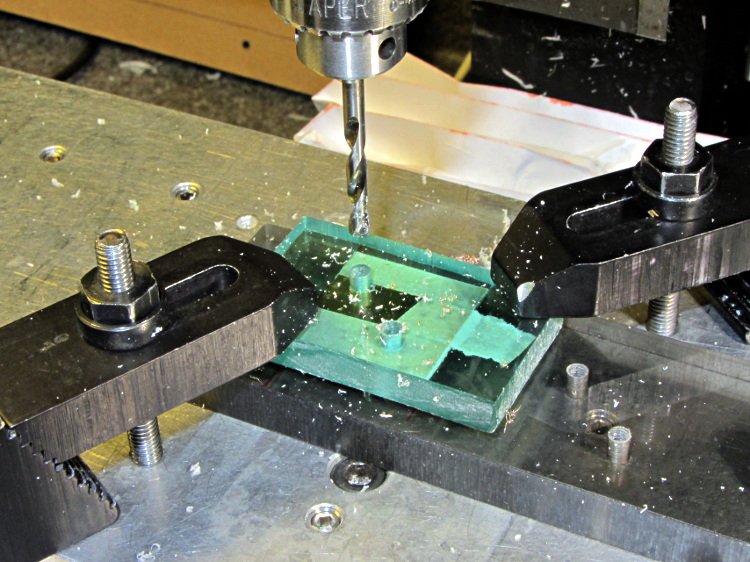
With all that in hand: stack, clamp, and drill some blanks:
Corner Clip Fixture – drilling
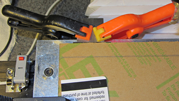
I tried milling a single drilled blank with a sacrificial plastic top plate:
Corner Clip Fixture – first milling setup
But that didn’t work well. I don’t know if this was due to an inept combination of climb milling, using the wrong speed / feed / material / cutter, and just poor style, but the edges of the blank mashed against the clamp plate and curled, instead of cutting cleanly:
Corner Clip Fixture – rounded-over milled edges
So I made a pair of aluminum plates to clamp both sides of the blanks, then milled another stack:
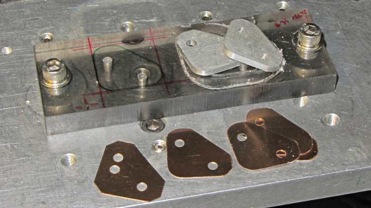
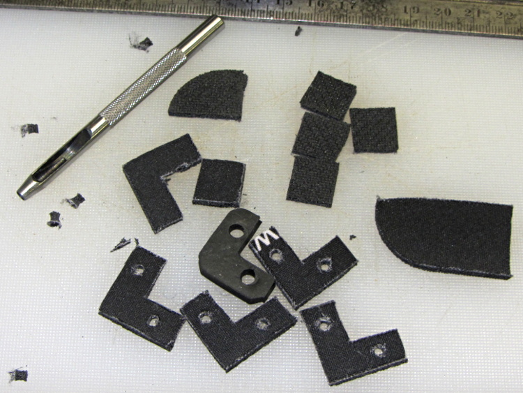
That worked quite well, although the top and bottom clips needed some slight attention from a riffler file and I did break the edges on all the clips. This shows four new clips along with a hand-cut prototype:
Corner Clip Fixture – end result
So I made a dozen more clips, picked the best eight for two sets, sent one set to Dan, installed the other, and … now I have a bunch of spares.
I suppose I should sell clip sets on Etsy / eBay to all the other M2 owners, but I have no idea how to price ’em. If you want some fancy corner clips, send whatever you think they’re worth … [grin]
The CNC version of the corner clips looks much better than the prototypes:
M2 glass retaining clip
Tightening the screws until the clip just flattens puts enough force on the glass + heat spreader stack to hold it firmly against the balls in the bottom pad. The solid rubber L-shaped bumpers and screws hold the glass in position against XY forces… and the whole affair looks much better than the original (and perfectly serviceable) bulldog clips. These clips free up the entire surface of the glass plate, minus four 12 mm triangles that you could, if you were desperate, print right over.
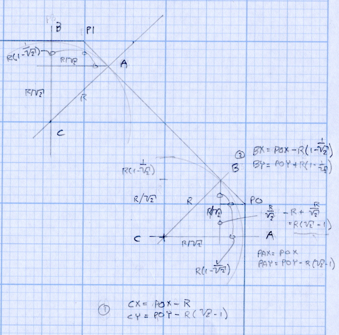
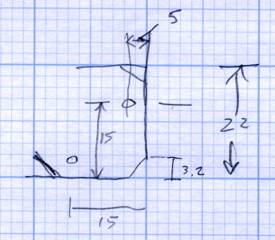
Although it’d be easier to just hack out an angular clip, I wrote a bit of G-Code to put a nice radius on each corner. The clip sits atop the rubber bumper with a 0.5 mm margin to keep the metal edges away from fingers; they’re smooth, but it’s still a strip of 6 mil (= 0.15 mm) phosphor bronze and feels a lot like a knife edge if you press hard enough.
The radius on the three outside corners is a special-case solution of the general circle-through-three-points problem, taking advantage of the symmetry and right-triangle-ness of the corners. This sketch shows the details:
M2 Platform Clip Doodles 4 – corner fairing with margin
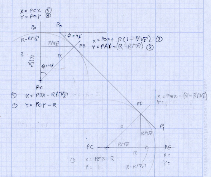
The two corners on the bevel over the glass plate have a fixed radius. I reworked my original fairing arc solution for outside cutting and doodled it up for this situation:
M2 Platform Clip Doodles 5 – bevel full solution
The outside corner radius worked out to 5 mm and I set the bevel radius at 3 mm. I think the latter made those corners a bit too sharp, but it’s Good Enough for my simple needs.
Drilling and machining the clips required a fixture:
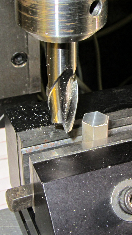
I used cutter diameter compensation to mill the edges, starting oversize by 1.5 mm and working downward by 0.5 mm on each pass to the actual diameter. That gradually trimmed off the edges without any excitement, so I could start with rough-trimmed stock and not worry about precision hand trimming.
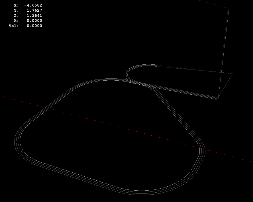
I thought climb milling (CW around the part) would produce better results, but it tended to smear the phosphor bronze against the fixture:
M2 Corner Clips – Climb milling tool paths
Conventional milling (CCW around the part) actually worked, but it required fancier entry and exit moves:
M2 Corner Clips – Conventional milling tool paths
This part is the kind and size of machining perfectly suited to a Sherline CNC mill…
The LinuxCNC G-Code source:
( M2 Build Platform Corner Clips )
( Ed Nisley - KE4ZNU - July 2013 )
( Fixture origin at right-front corner pip )

( Flow Control )
#<_Do_Drill> = 0		( Drill two holes in clip )
#<_Do_Mill> = 1			( Mill clip outline )
#<_Climb_Mill> = 0		( 0 = conventional 1 = climb)

( Fixture info )
#<_Drill_X_Fixture> = 5.0	( Drill station origin )
#<_Drill_Y_Fixture> = 5.0

#<_Drill_Num> = 30			( Drill number in tool table)
#<_Drill_Retract> = 15
#<_Drill_Depth> = -1.0
#<_Drill_Feed> = 300
#<_Drill_Speed> = 3000

#<_Mill_X_Fixture> = 40.0	( Mill station origin )
#<_Mill_Y_Fixture> = 5.0

#<_Mill_Num> = 3			( Mill number in tool table)
#<_Mill_Dia> = 4.60			( actual tool diameter)
#<_Mill_Dia_Incr> = 0.50
#<_Mill_Dia_Steps> = 3
#<_Mill_Retract> = 15
#<_Mill_Depth> = -0.5
#<_Mill_Feed> = 300
#<_Mill_Speed> = 8000

(----------------)

(  Initialize first tool length at probe switch )
(     Assumes G59.3 is still in machine units, returns in G54 )
(  ** Must set these constants to match G20 / G21 condition! )

#<_Probe_Speed>     = 400            ( set for something sensible in mm or inch )
#<_Probe_Retract>   =   1            ( ditto )

O<Probe_Tool> SUB

G49                     ( clear tool length compensation )
G30                     ( move above probe switch )
G59.3                   ( coord system 9 )

G38.2 Z0 F#<_Probe_Speed>           ( trip switch on the way down )
G0 Z[#5063 + #<_Probe_Retract>]     ( back off the switch )
G38.2 Z0 F[#<_Probe_Speed> / 10]    ( trip switch slowly )

#<_ToolZ> = #5063                    ( save new tool length )

G43.1 Z[#<_ToolZ> - #<_ToolRefZ>]    ( set new length )

G54                     ( coord system 0 )
G30                     ( return to safe level )

O<Probe_Tool> ENDSUB

(-------------------)
(-- Initialize first tool length at probe switch )

O<Probe_Init> SUB

#<_ToolRefZ> = 0.0      ( set up for first call )

O<Probe_Tool> CALL

#<_ToolRefZ> = #5063    ( save trip point )

G43.1 Z0                ( tool entered at Z=0, so set it there )

O<Probe_Init> ENDSUB

(-------------------)
(-- Mill one pass around outline with tool diameter passed in #1 )

O<MillOutline> SUB

#<X_Size> = 22.0		( size of support spider pad = nominal clip size )
#<Y_Size> = 22.0
#<Base_Bevel> = 3.2		( X or Y length of corners clipped from spider pad )

#<Bevel_Size> = 9.0		( remaining part of trimmed edges on clip )
#<Bevel_Radius> = 3.0	( fairing radius at bevel corners on clip)

#<R_Div_Root2> = [#<Bevel_Radius> / SQRT[2]]
#<R_1M_Recip_R2> = [#<Bevel_Radius> * [1 - 1/SQRT[2]]]
#<R_Root2_M1> = [#<Bevel_Radius> * [SQRT[2] - 1]]

#<Margin> = 0.5			( recess inside of nominal )

#<X_Min> = [#<Margin>]
#<X_Max> = [#<X_Size> - #<Margin>]

#<Y_Min> = [#<Margin>]
#<Y_Max> = [#<Y_Size> - #<Margin>]

#<Corner_Rad> = [[#<Margin> * [1 - SQRT[2]] + [#<Base_Bevel> / SQRT[2]]] / [SQRT[2] - 1]]

O<Climb> IF [#<_Climb_Mill>]

G0 X#<X_Min> Y[#<Y_Max> + 3*#<_Mill_Dia>]
G1 Z#<_Mill_Depth> F#<_Mill_Feed>

G41.1 D#1

G3 X[#<X_Min>] Y#<Y_Max> I0 J[0-1.5*#<_Mill_Dia>]	( cutter comp on: entry move)

G1 X[#<Bevel_Size> - #<R_Root2_M1>]
G2 X[#<Bevel_Size> + #<R_1M_Recip_R2>] Y[#<Y_Max> - #<R_1M_Recip_R2>] J[0-#<Bevel_Radius>]

G1 X[#<X_Max> - #<R_1M_Recip_R2>] Y[#<Bevel_Size> + #<R_1M_Recip_R2>]
G2 X#<X_Max> Y[#<Bevel_Size> - #<R_Root2_M1>] I[0-#<R_Div_Root2>] J[0-#<R_Div_Root2>]

G1 Y[#<Y_Min> + #<Corner_Rad>]
G2 X[#<X_Max> - #<Corner_Rad>] Y#<Y_Min> I[0-#<Corner_Rad>] J0

G1 X[#<X_Min> + #<Corner_Rad>]
G2 X#<X_Min> Y[#<Y_Min> + #<Corner_Rad>] I0 J#<Corner_Rad>

G1 Y[#<Y_Max> - #<Corner_Rad>]
G2 X[#<X_Min> + #<Corner_Rad>] Y#<Y_Max> I#<Corner_Rad> J0

G40

G0 X#<X_Min> Y[#<Y_Max> + 3*#<_Mill_Dia>]
(G3 X#<Bevel_Size> Y[#<Y_Max> + 3*#<_Mill_Dia>] I0 J[1.5*#<_Mill_Dia>])	( cutter comp off: safe exit)

G0 X#<X_Min>			( return to start)

O<Climb> ELSE

G0 X#<X_Size> Y[#<Y_Size> + #1/2]

G1 Z#<_Mill_Depth> F#<_Mill_Feed>

G42.1 D#1

G1 X#<Bevel_Size> Y[#<Y_Max>]	( cutter comp on: entry move)

G1 X[#<X_Min> + #<Corner_Rad>]
G3 X#<X_Min> Y[#<Y_Max> - #<Corner_Rad>] I0 J[0-#<Corner_Rad>]

G1 Y[#<Y_Min> + #<Corner_Rad>]
G3 X[#<X_Min> + #<Corner_Rad>] Y[#<Y_Min>] I#<Corner_Rad> J0

G1 X[#<X_Max> - #<Corner_Rad>]
G3 X[#<X_Max>] Y[#<Y_Min> + #<Corner_Rad>] I0 J#<Corner_Rad>

G1 Y[#<Bevel_Size> - #<R_Root2_M1>]
G3 X[#<X_Max> - #<R_1M_Recip_R2>] Y[#<Bevel_Size> + #<R_1M_Recip_R2>] I[-#<Bevel_Radius>]

G1 X[#<Bevel_Size> + #<R_1M_Recip_R2>] Y[#<Y_Max> - #<R_1M_Recip_R2>]
G3 X[#<Bevel_Size> - #<R_Root2_M1>] Y#<Y_Max> I[-#<R_Div_Root2>] J[-#<R_Div_Root2>]

G2 Y[#<Y_Max> + 3*#<_Mill_Dia>] J[#<_Mill_Dia>*1.5]		( get away from corner)
G40

G0 X#<X_Size>					( cutter comp off: safe exit)
G0 Y[#<Y_Size> + #1/2]			( return to start)

O<Climb> ENDIF

O<MillOutline> ENDSUB

(----------------)
( Start machining... )

G17 G40 G49 G54 G80 G90 G94 G99	( reset many things )

G21								( metric! )
G91.1 							( incremental arc centers)

(msg,Verify: G30.1 position in G54 above tool change switch? )
M0
(msg,Verify: fixture origin XY touched off? )
M0
(msg,Verify: Current tool Z=0 touched off? )
M0

( Set up probing)
O<Probe_Init> CALL
T0 M6

(---- Drill holes)

O<DoDrill> IF [#<_Do_Drill>]

(debug,Insert drill tool = #<_Drill_Num>)
T#<_Drill_Num> M6
O<Probe_Tool> CALL
(debug,Set spindle to #<_Drill_Speed> rpm )
M0

G0 X#<_Drill_X_Fixture> Y#<_Drill_Y_Fixture>
G0 Z#<_Drill_Retract>

G10 L20 P2 X0 Y0 Z#<_Drill_Retract>	( P2 = G55)
G55					( drill station coordinates )

G81 X5.0 Y15.0 Z#<_Drill_Depth> R#<_Drill_Retract> F#<_Drill_Feed>

G81 X15.0 Y5.0

G54

O<DoDrill> ENDIF

(---- Mill outline )
( Start with large diameter and end with actual diameter to trim in stages)

O<DoMill> IF [#<_Do_Mill>]

(debug,Insert mill tool = #<_Mill_Num>)
T#<_Mill_Num> M6
O<Probe_Tool> CALL
(debug,Set spindle to #<_Mill_Speed> rpm )
M0

G0 X#<_Mill_X_Fixture> Y#<_Mill_Y_Fixture>
G0 Z#<_Mill_Retract>

G10 L20 P2 X0 Y0 Z#<_Mill_Retract>	( P2 = G55)
G55					( mill station coordinates )

#<PassCount> = 0

O<MillLoop> DO
#<Diameter> = [#<_Mill_Dia> + [#<_Mill_Dia_Steps> - #<PassCount>]*#<_Mill_Dia_Incr>]

O<MillOutline> CALL [#<Diameter>]

#<PassCount> = [#<PassCount> + 1]
O<MillLoop> WHILE [#<PassCount> LE #<_Mill_Dia_Steps>]

( Finishing pass with zero cut )
O<MillOutline> CALL [#<Diameter>]

G0 Z#<_Mill_Retract>
G54

O<DoMill> ENDIF

G30

(msg,Done!)
M2
The rest of the doodles, which don’t match up with the final G-Code because they represent the earliest versions of the layout:
In the course of normal events around here, the M2 gets tipped to one side or the other. Every time that happens, I rediscover the blindingly obvious fact that there’s nothing holding the glass build plate and the heater to the support spider:
M2 build platform corner
A few minutes with a metric ruler produced some useful dimensions for the ends of the spider’s arms:
M2 Platform Support Spider Pad Dimensions
The Big Box o’ Foamy Things emitted a mouse pad (remember mouse pads?) of exactly the right thickness to bring the corner pads just barely above the level of the glass plate, thus allowing for slight compression:
M2 corner bumpers
That’s a 1/8 inch hole punch, which is close enough to the M3 screw diameter in foam rubber. It worked fine for the balls in the corner support pads, too.
The long-suffering shop scissors produced results about as pretty as one might expect:
img_3157 – M2 platform retaining clips – raw cut
Which is to say, not very.
The material is 6 mil (about 0.15 mm) phosphor bronze, nice and springy. Combined with ripply edges and sharp corners, you get perfectly serviceable serrated knife blades suitable for use in traditional shop ceremonies of ritual scarification of the fingertips.
I stacked the slips, clamped them to the Sherline’s table between sacrificial plastic sheets, used manual CNC to poke a pair of #31 holes (0.120 inch, about the right clearance for M3 screws) at the right spots, and then stacked everything up on the M2:
M2 platform retaining clip oops – in place
The alert reader will notice a third #31 hole at the wrong spot, which was the first one I drilled and partially explains the lack of pictures of the operation.
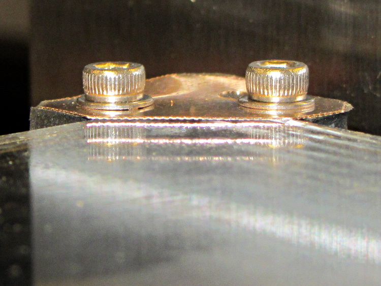
Sighting across the platform shows that the clip doesn’t lie quite flat on the glass, due to the scissors-cut bending:
M2 platform retaining clip – edge view
However, four of these clips hold the glass firmly to the heat spreader and eliminate the need for the stock bulldog clips, which is what I wanted to find out.
But they’re ugly and I don’t want to explain that extra hole…
I’m planning to put all the stepper driver bricks, solid state relays, power suppliers, miscellaneous doodads, and suchlike that will interface LinuxCNC with the M2 printer into a repurposed Dell desktop PC case.
The front of the case had some tabs sticking out that anchored / aligned / captured various bits of hardware; grabbing them with a Vise-Grip, wiggling until the steel failed, and then filing the raw edge solved that problem:
Dell PC case – removing small tabs
The PC had room for a diskette drive, with a lip protruding below the opening:
Dell PC case – diskette drive slot tab
A welding pliers wiggled nearly the entire tab at once:
PC case – removing diskette drive tab
The bulky Dell front panel had four locating pins that mated with four round holes, one of which appears in the first picture. I wanted a somewhat less butt-ugly front than the bare metal grill, but still with some air flow into the case, so I found some 1/4 inch diameter standoffs tapped 4-40 that fit snugly in the holes and cut them to length:
Dell PC case – trimming panel mounts
Another defunct Dell case contributed a side panel with roughly the right color. Four match-drilled clearance holes later:
Dell PC case – vent panel
Just for effect, I squared up a slab of nice smoke-brown polycarb to cover the upper opening and perhaps hold das Blinkenlights. The slab was, as almost always happens, slightly too large for the Sherline, so I had to reclamp it to clean up all the sides. It came out about half a millimeter out of square and, being that type of guy, I clamped a block to the back of the table with a suitable spacer against the wide side, removed the spacer, loosened the step clamp on that end, rotated the slab against the block, made another pass, and it came out perfectly square:
Dell PC case – squaring polycarb panel
Four match-drilled holes and some epoxy later:
Dell PC case – polycarb panel mounts
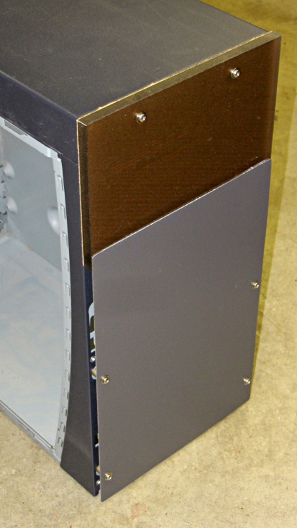
I’ll probably put the main AC switch on that top panel, but it looks pretty good even with the protective paper on the back:
Dell PC case – front panels
I must mill a recess under the vent panel and counterbore the screw heads so everything fits flush and lines up neatly.
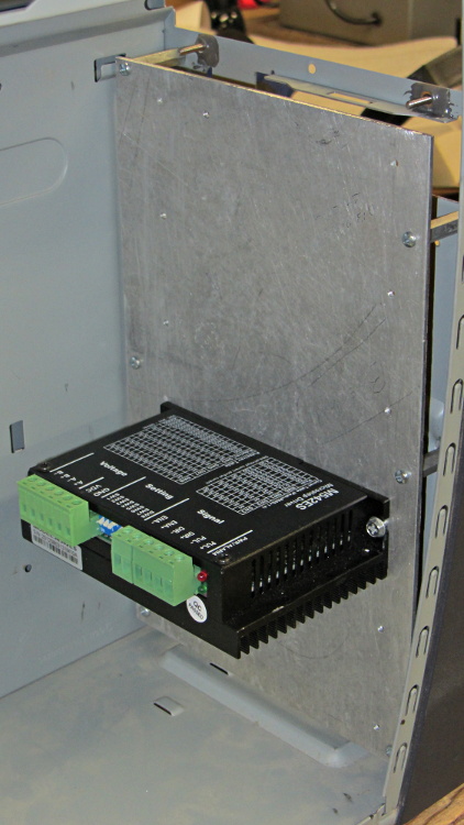
Another chunk of aluminum will hold the stepper driver bricks along the front of the case:
Dell PC case – stepper drive panel
I laid out the holes with a square, eyeballed the spacing on a machinist’s scale, manually punched / drilled / tapped the holes, and it’s all good. The standoffs provide a bit of airflow around the edges; I don’t expect the drivers to get more than slightly warm, because they’re running near the bottom of their current rating. Incidentally, that sheet is a different and much nicer alloy than the pure aluminum I jeweled for the main base plate and will probably not use.
The 24 VDC power supply will mount on the top of the case, up where the Dell PC supply used to reside. The supply has M4 tapped holes and, of course, I don’t have any such standoffs, but I did find some hex standoffs with 6-32 tapped holes on both ends. Bandsaw ’em in half and clean up the raw end to the proper length:
Dell PC case – power supply standoffs – trimming
Center drill in the lathe / drill / tap an M4 thread in each one, saw off some M4 screws, slather with red Loctite, insert studs into standoffs, and that should hold the power supply in place with 6-32 screws through the case top:
Dell PC case – power supply standoffs
More Quality Shop Time lies ahead, but it’s coming together…
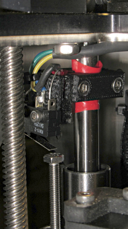
The printed bracket for the M2’s Z axis home switch doesn’t get a good grip on the oiled steel rod, so it can slide around just a little bit when nudged. That doesn’t happen often, but when it does, all your careful alignment Goes Away.
A single wrap of silicone tape solves that problem:
Z min switch on silicone tape
While I was in there, I replaced the socket-head cap screw I’d been using with a longer hex bolt and swapped the nylock nut for a plain nut that’s easier to adjust. I should file the raised markings off the top of the bolt head so it presents a smooth surface to the switch.
The original M2 Z axis motor required extremely low acceleration and speed settings, because it produced barely enough torque to lift the weight of the Z stage + HBP + glass platform. The new motor can produce about twice as much torque, so it should perform much better: all of the additional torque can go to accelerating that weight.
I weighed all the bits and pieces while I had the M2 apart, although I forgot to weigh the motor + leadscrew separately:
2.2 kg – Z stage including Z motor
290 g – old Z motor + leadscrew + nut
220 g – motor similar to new motor minus leadscrew
963 g – HBP + glass + clips
So, in round numbers, the whole assembly weighs about 3 kg = 29 N = 6.6 pounds. That’s surprisingly close to my original guesstimate of 3 kg = 7 pounds; I round in the worse direction when there’s only one significant figure.
With the new motor in place, the rods & leadscrew lubed up, and the platform in place, it’s not quite heavy enough to fall under its own weight; it would just barely fall with the old motor. The slightest touch moves it along, though, which means that the angle of friction is just over the lead angle.
The thread form is 30° trapezoidal, so the pitch diameter for an 8 mm OD thread is about PD = 7.2 mm. For an 8 mm lead thread, the lead angle is 19.5° = arctan(8 mm / π · 7.2 mm). Wikipedia’s entry on leadscrews reports the coefficient of friction for oily steel on bronze is between 0.1 and 0.16 for a buttress thread. This thread is trapezoidal, the nut isn’t worn in, the alignment’s probably off a bit, and so forth and so on; so let’s say the angle of friction is 20° and the coefficient of friction is 0.35.
If the new motor can produce, let’s suppose, 500 mN·m of torque, then the upward force on the stage will be:
(2 T) / (PD tan(lead angle + friction angle)) = 1 N·m / (7.2 mm x 0.84) = 165 N
In the ideal world of physics, applying 165 N to a 3 kg stage should accelerate it at 55 m/s2 = 55000 mm/s2 = 5 G.I don’t believe that for a moment, either, particularly because stepper motor torque drops off dramatically at higher speeds.
However, that suggests that, at a rational acceleration, the maximum stepper motor speed could very well be limited by the Marlin 40 kHz step frequency limit to 100 mm/s = (40000 step/s) / (400 step/mm) = 6000 mm/min.
Given that I’m running the XY motors at 5000 mm/s2, I set the Z acceleration to 5000 mm/s2 and discovered that it would stall on the way to 100 mm/s. Backing off to 2000 mm/s2 worked better, so I tweaked the Marlin configuration thusly:
It should be possible to sense the filament diameter with a cheap webcam and some optics:
Filament Diameter Sensor – Optical Path Layout
The general idea:
Given that LinuxCNC runs on a bone-stock PC, you can plug in a stock USB webcam and capture pictures (I have done this already). Because LinuxCNC isolates the motion control in a hard real time process, you can run heavy metal image manipulation code in userland (think ImageMagick) without affecting the motors.
So you can put a macro lens in front of a webcam (like that macro lens holder) and mount it just above the extruder with suitable lighting to give a high-contrast view of the filament. Set it so the filament diameter maps to about 1/4 of the width of the image, for reasons explained below.
For a crappy camera with 640×480 resolution, this gives you 160 pixel / 1.75 mm filament = 91 pixel/mm → about 0.01 mm resolution = 0.6%. Use a better camera, get better resolution: 1280 pixel = 0.3% resolution.
That gives you roughly 1% or 0.5% resolution in area. This is pretty close to the holy grail for DIY filament diameter measurement.
Add two first-surface mirrors / prisms aligned at right angles, so that the camera sees three views of the filament: straight on, plus two views at right angles, adjacent to the main view. Set the optics so they’re all about 1/4 of the image width, to produce an image with three parts filament and one part high-contrast background separating them. This is the ideal, reality will be messier.
Figure 1 shows an obvious arrangement, the mirrors in Figure 2 give more equal distances.
You could align the mirrors to provide three views at mutual 120° angles, which would equalize the distances and give you three identical angles for roundness computation, should that matter.
Diameter measurement process:
Extract one (*) scan line across the image.
Convert to binary pixels: 1 = filament, 0 = background, perhaps with ImageMagick auto thresholding.
Add pixel values across the line, divide by 3, multiply by mm/pixel → average filament diameter.
Done!
Adding binary pixels is easy: it’s just the histogram, which ImageMagick does in one step. Dump data to a file / pipe, process it with Python. It all feeds into a LinuxCNC HAL component, which may constrain the language to C / Python / something else.
(*) You can get vertical averaging over a known filament length, essentially for free. Extract three (or more) scan lines, process as above, divide by 3 (or more), and you get a nicely averaged average.
Win: the image is insensitive to position / motion / vibration within reasonable limits, because you’re doing the counting on pixel values, not filament position. The camera can mount near, but not on, the extruder, so you can measure the filament just above the drive motor without cooking the optics or vibrating the camera to death.
Win: it’s non-contacting, so there’s not much to get dirty
Win: you get multiple simultaneous diameter measurements around one slice of the filament
You could mount the camera + optics at one end of the printer’s axis (on the M2, the X axis). Drive the extruder to a known X position, take a picture of the straight-on view, drive to another position, take a picture of the mirrored views, and you have two pictures in perfect focus. Combine & process as above.
You can do that every now and again, because any reasonable filament won’t vary that much over a few tens of millimeters. Maybe you do it once per layer, as part of the Z step process?
You could generalize this to a filament QC instrument that isn’t on the printer itself: stream the filament from spool to spool while measuring it every 10 mm, report the statistics. That measurement could run without stopping, because you don’t reposition the filament between measurements: it’s all fixed-focus against a known background. You could have decent roller guides for the filament to ensure it’s in a known position.
Heck, that instrument could produce a huge calibration file that gives diameter / roundness vs. position along the entire length of the filament. Use it to accept/reject incoming plastic supplies or, even better, feed the data into the printer along with the spool to calibrate the extrusion on the fly without fancy optics or measurements.
Dan wonders if this might be patented. I’m sure it is: I’m nowhere near as bright as the average engineering bear at a company that’s been spending Real Money for three decades. My working assumption: all the knowledge is out there, behind a barrier I can’t see through or reach around: there’s no point in looking for it beyond a casual Google search on the obvious terms that, so far, hasn’t produced anything similar.
Memo to Self: Might even be marketable, right up until they crush me like a bug…