Ed Nisley's Blog: Shop notes, electronics, firmware, machinery, 3D printing, laser cuttery, and curiosities. Contents: 100% human thinking, 0% AI slop.
The HP 7475A plotter comes with a transparent smoke-brown plastic flip-up lid covering the carousel and pen holder, presumably to keep dust and fingers out of the moving parts. That lid also has has the side effect of limiting the pen length, presumably because HP didn’t want the 7475A to eat into their large-format plotter market. In any event, removing the lid leaves another barrier to longer pens: the rugged plastic case between the carousel and the pen holder.
That’s from an earlier test, before I sawed the slot in the case, with all the machinery behind the pen holder in full view.
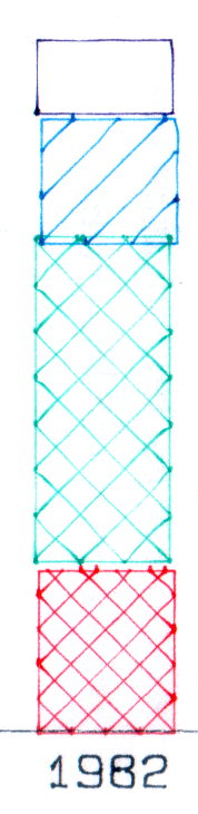
The test plot, with the proper pen colors and widths loaded in the carousel, looks pretty good:
HP7475A – Sakura Micro Pens – self-test plot
The pen holder wasn’t intended to support a long pen, so that shaft tends to torque the pen tip out of position, particularly while drawing characters:
HP 7475A – long black pen – misalignment
The various pen tips don’t all point to the same place:
HP 7475A – long RGBK pen misalignment
That could be non-concentric pen adapters, misalignment in the pen holder, or slightly off-center pen nibs. The offsets between the colors remains consistent in all the bar-chart columns, so the pen adapters aren’t shifting in the holder.
The worst-case error between bar-chart rectangles amounts to 0.5 mm parallel to the pen holder motion and 0.8 mm parallel to the paper motion. In round numbers, the pen tip is 30 mm from the flange, so moving it 0.5 mm to the side tips the pen 1°. The flange is 17 mm OD, which means a 1° tilt raises one edge by 0.3 mm or both edges by ±0.15 mm. Given a 0.25 mm 3D printed thread thickness, that’s certainly within reach of a random plastic blob.
Looking closely at the printed-and-glued flange shows plenty of room for misunderstanding betwixt pen and holder, even after cleaning off all that PETG hair:
HP7475A – Sakura Micro Pen Adapter – vs HP pen
Given that the Sakura pens aren’t intended for this application, a slight tip misalignment due to body molding tolerances isn’t unreasonable; a perfect adapter might not solve the problem.
The HP maintenance manual lists a BASIC program to produce a test plot that verifies pen alignment, although the prospect of transliterating 2+ pages of quoted strings from a scanned document doesn’t fill me with desire.
First up: it’s not our projector, which means the usual Rules of Engagement do not apply.
A few small black plastic fragments fell out of the Epson S5 projector’s carry bag, the front foot wouldn’t remain extended, and, as one might expect, the two incidents were related. Mary needed it for the gardening class she was teaching the next evening, sooooo…
A pair of plastic snaps release the entire foot assembly from the front of the projector:
Epson S5 Projector Foot – assembled
It became obvious that we didn’t have all the fragments, but it was also obvious that, even if we had the pieces, a glued assembly wouldn’t last very long.
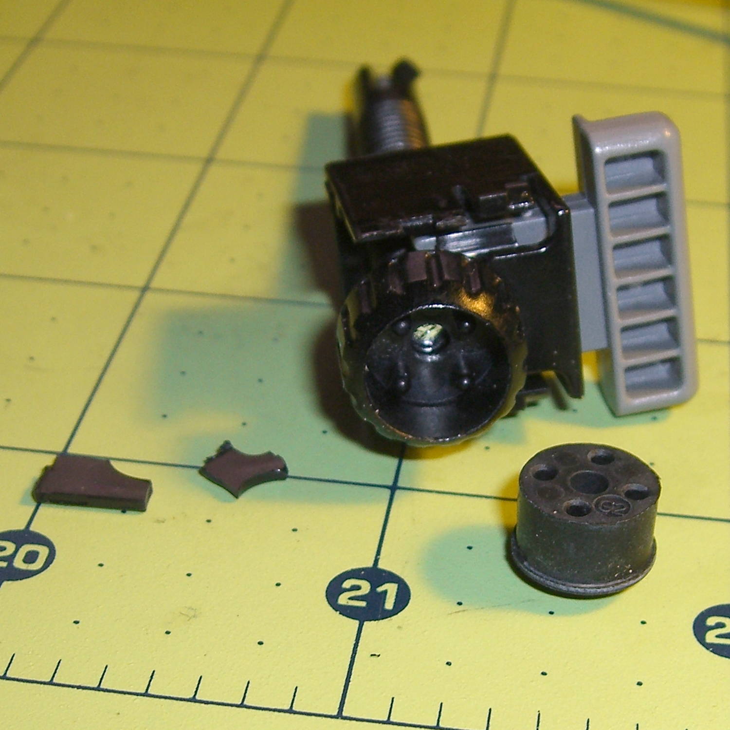
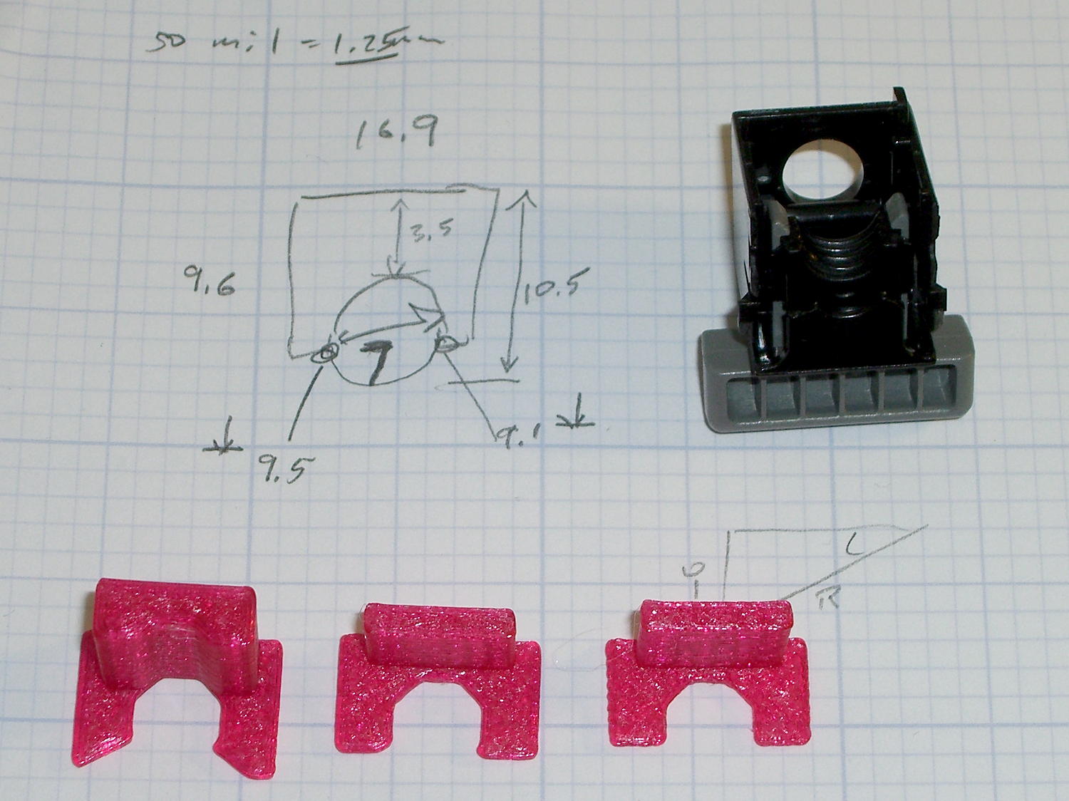
The threaded plastic stem surrounds a steel pin that’s visible when you remove the rubber foot pad. That pin holds the latch on the end of the stem outward, so that the stem can’t fall out. Drive out the pin with a (wait for it) pin punch inserted from the foot pad end, which reveals the broken plastic doodad:
Epson S5 Projector Foot – stem removed
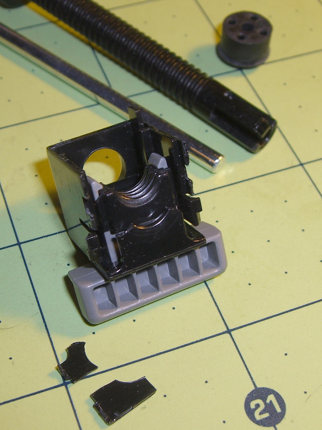
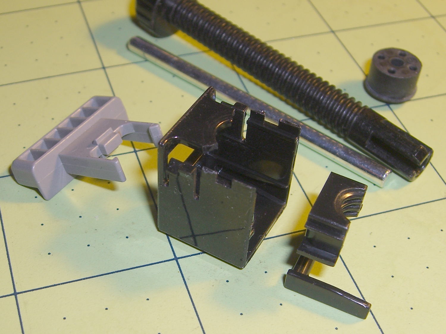
Release the latches on the gray handle and the intricate half-nut that engages the threaded stem slides out:
Epson S5 Projector Foot – disassembled
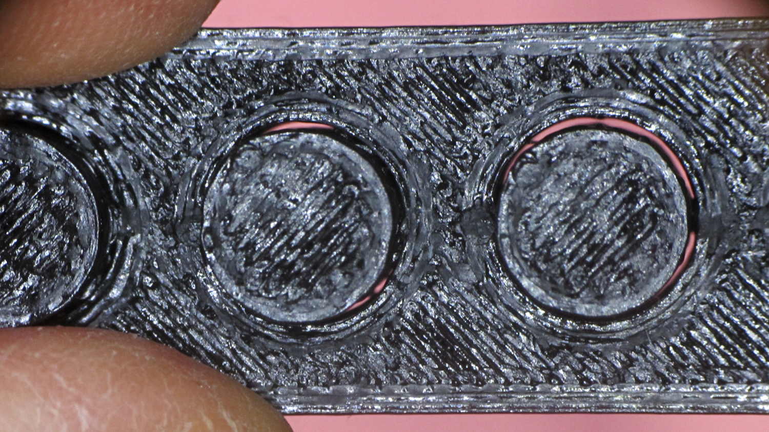
A plastic spring in the boxy shell pushes the gray handle and half-nut against the stem, holding the stem in place. Pushing the gray handle upward (on the projector, downward in the picture, yes, your fingertip can feel those ribs just fine) pulls the half-nut away from the stem and lets the stem slide freely. With the stem extended, the projector leans on the stem, pushes it against the half-nut, and you can fine-tune the angle by turning the stem; the splines around the rubber foot encourage that. You can pull the stem outward without activating the latch, which probably broke the fragile plastic plate.
A doodle showing the estimated measurements, plus three 3D printed prototypes required to get a good fit:
Epson S5 Projector Foot – measurements and versions
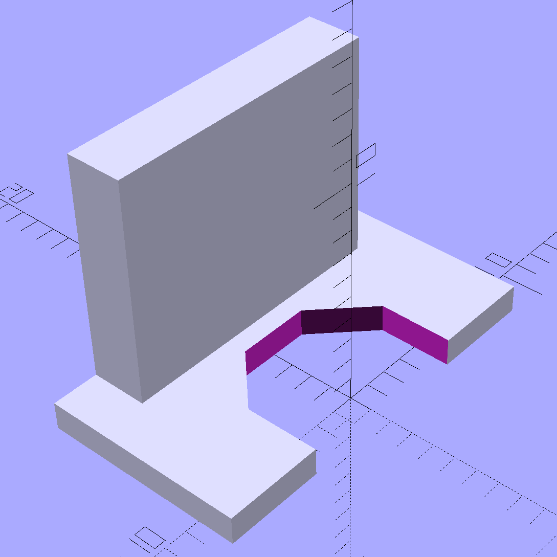
The solid model looks about like you’d expect:
Epson S5 Projector foot latch – solid model
The first version (leftmost of the three sitting on the doodle, above) had angled ends on the tabs that I intended to match up with the stubs remaining on the OEM latch. The part fit better with shorter tabs and the angles vanished on third version; the statements remain in the OpenSCAD source, but the short tabs render them moot.
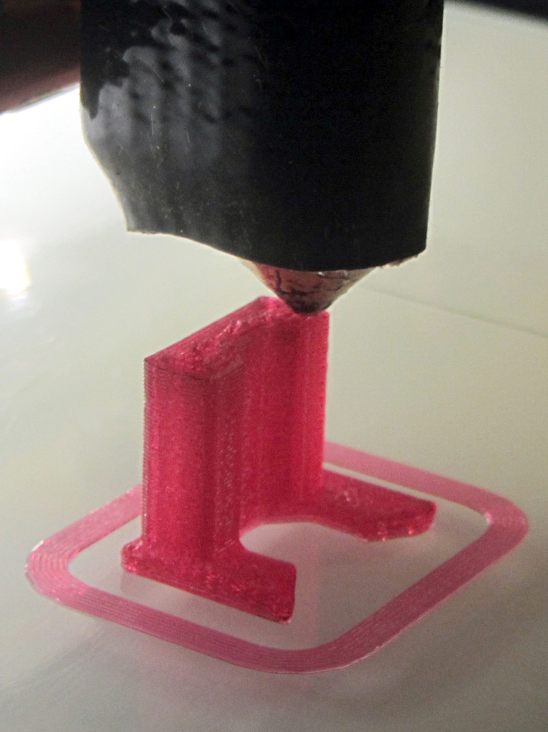
Apparently I got the cooling & fan & minimum layer time pretty close to right for PETG, as each of those three towers printed singly with no slumping:
Epson S5 Projector Foot – V1 on platform
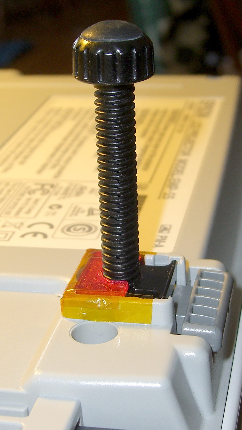
The third version snapped into place, with a square of tapeless sticky on the back to help keep it there. The obligatory Kapton tape helps retain it, but I have no illusions about the permanence of this repair:
Epson S5 Projector Foot – repair installed
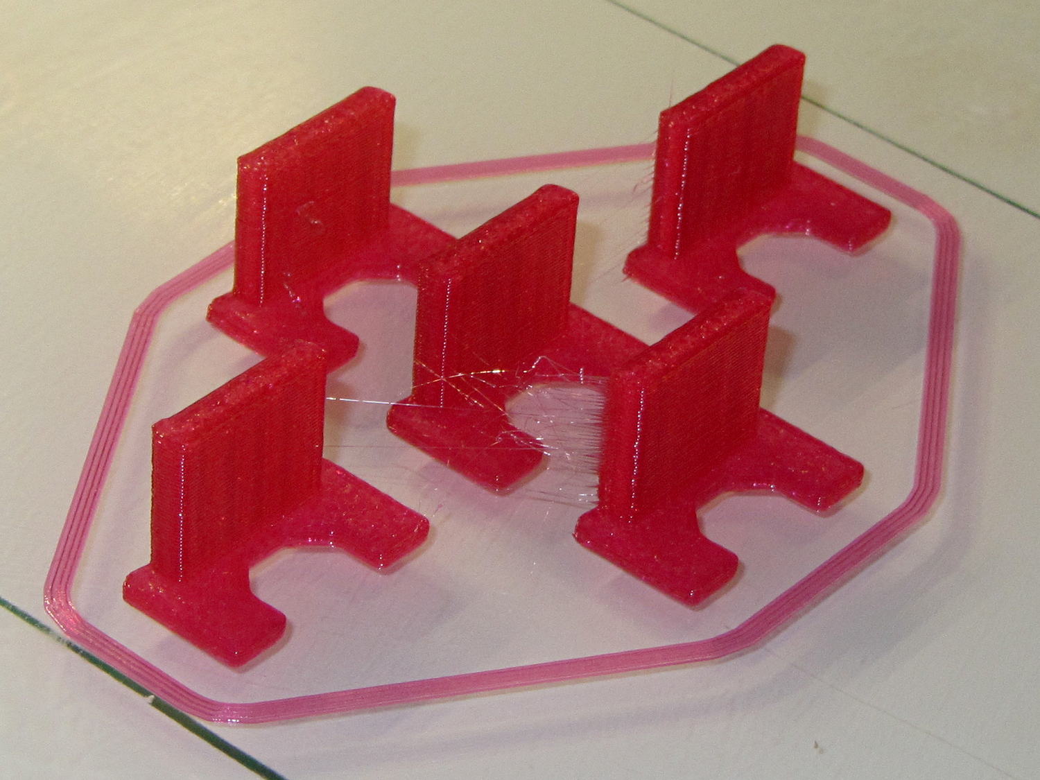
Because I know the problem will happen again, I called for backup:
Epson S5 Projector Foot – 5 copies
That’s with Hilbert Curve top / bottom fill, three top / bottom layers, 20% rectilinear infill, and two perimeters. Extruder at 250 °C, platform at 90 °C, hairspray for adhesion.
Note, however, the hair-fine strings connecting the towers. Retraction must be just about right, as shown by the overall quality of the objects, but PETG comes out really stringy. Choosing an infill pattern to minimize retraction seems like a big win; relatively sparse 3D Honeycomb works well on larger objects, but these were so small that straight line fill fit better. The flat plates on the bottom consist of five completely solid layers of PETG.
Reports from the field indicate complete success: whew!
One could, of course, just buy a replacement from the usual eBay supplier, if one were so inclined.
The solid box lets you check the outside dimensions (20 x 20 x 5 mm) and the slicer’s infill parameters.
The first few attempts with a new setup won’t look very good, but that’s the whole point:
M2 V4 Calibration Objects
Getting a workable profile and accurate Z-axis setting required maybe a dozen quick prints & parameter changes. After that, they’re good for verifying that any change you make hasn’t screwed up something beyond recovery.
Put five of them on the platform to verify overall alignment (“leveling”) and first-layer thickness:
Thinwall Calibration Cubes – 5 copies
A few iterations will generate plenty of show-n-tell tchotchkes:
Thinwall open boxes from platform leveling
As nearly as I can tell, if you can’t print these reliably, there’s no point in trying to print anything else.
Even better, when you suddenly can’t print anything else reliably, these simple boxes will tell you what’s gone wrong…
Our Larval Engineer volunteered to convert the lens from a defunct magnifying desk lamp into a hand-held magnifier; there’s more to that story than is relevant here. I bulldozed her into making a solid model of the lens before starting on the hand-holdable design, thus providing a Thing to contemplate while working out the holder details.
That justified excavating a spherometer from the heap to determine the radius of curvature for the lens:
Student Sphereometer on lens
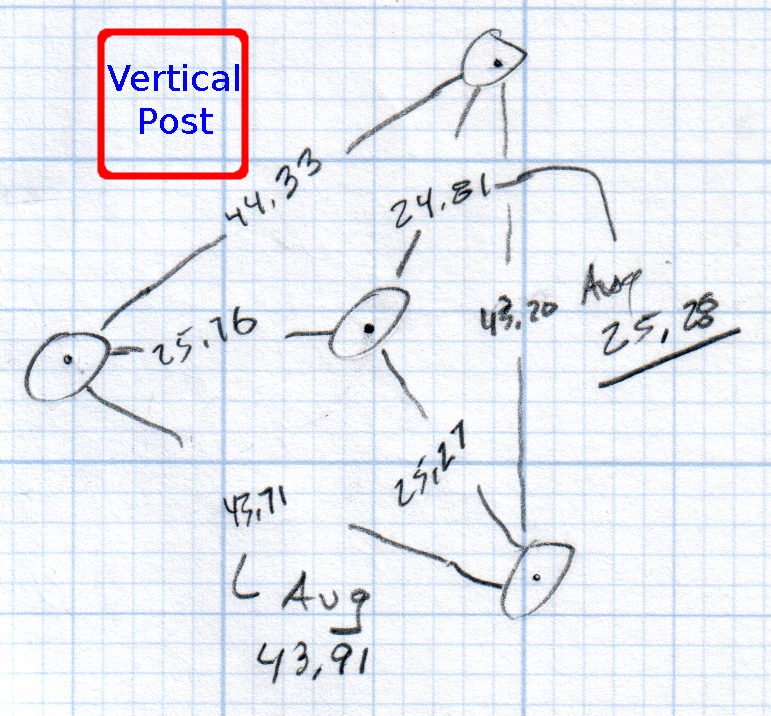
You must know either the average radius / diameter of the pins or the average pin-to-pin distance. We used a quick-and-dirty measurement for the radius, but after things settled down, I used a slightly more rigorous approach. Spotting the pins on carbon paper (!) produced these numbers:
Sphereometer Pin Radii
The vertical scale has hard-metric divisions: 1 mm on the post and 0.01 on the dial. You’d therefore expect the pins to be a hard metric distance apart, but the 25.28 mm average radius suggests a crappy hard-inch layout. It was, of course, a long-ago surplus find without provenance.
The 43.91 mm average pin-to-pin distance works out to a 50.7 mm bolt circle diameter = 25.35 mm radius, which is kinda-sorta close to the 25.28 mm average radius. I suppose averaging the averages would slightly improve things, but …
The vertical distance for the lens in question was 0.90 mm, at least for our purposes. That’s the sagitta, which sounds cool enough to justify this whole exercise right there. It’s 100 mm in diameter and the ground edge is 2.8 mm thick, although the latter is subject to some debate.
Using the BCD, the chord equation applies:
Height m = 0.90 mm
Base c = 50.7 mm
Lens radius r = (m2 + c2/4) / 2m = 357.46 mm
Using the pin-to-pin distance, the spherometer equation applies:
Pin-to-pin a = 43.91 mm
Sagitta h = 0.90 mm
Lens radius R = (h/2) + (a2 / 6h) = 357.50 mm
Close enough, methinks.
Solving the chord equation for the total height of each convex side above the edge:
Base c = 100 mm
Lens radius r = 357.5 mm
Height m = r – sqrt(r2 -c2/4) = 3.5 mm
So the whole lens should be 2 · 3.5 + 2.8 = 9.8 mm thick. It’s actually 10.15 mm, which says they were probably trying for 10.0 mm and I’m measuring the edge thickness wrong.
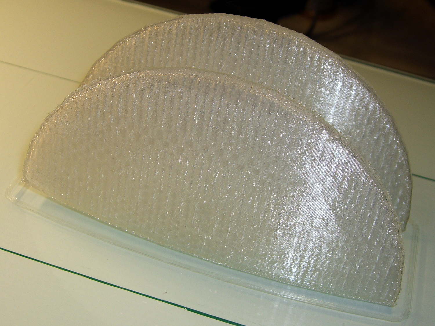
She submitted to all this nonsense with good grace and cooked up an OpenSCAD model that prints the “lens” in two halves:
Printed Lens – halves on platform
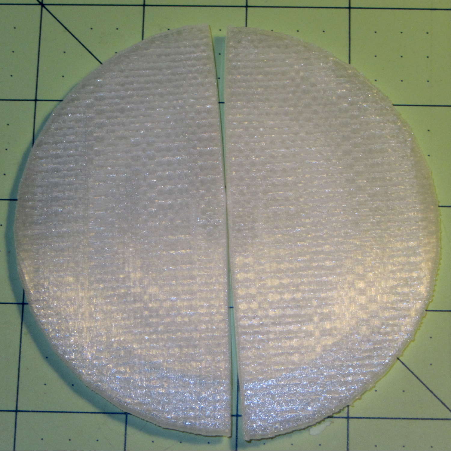
Alas, those thin flanges have too little area on the platform to resist the contraction of the plastic above, so they didn’t fit together very well at all:
Printed Lens – base distortion
We figured a large brim would solve that problem, but then it was time for her to return to the hot, fast core of college life…
In the quest for More Light around the Kenmore 158’s needle, I’m replacing the pair of 10 mm LEDs with a pair of 21 V / 115 mA = 2.5 W surface-mount emitters that require a good heatsink. Because the heatsink must mount inside the sewing machine’s end cap, there’s not much air circulation: when sizing the heatsink, I figure that nothing exceeds like excess.
There doesn’t seem to be any way to measure the available space inside the hinged end cap, so the plan is to fit the largest possible heatsink, run it for a while, and then build a smaller (and presumably less awkward) heatsink based on those measurements.
I sawed a slice off an aluminum heatsink harvested from a junked PC, wrapped masking tape around it, and filled it with machinable wax to prevent the fins from chattering:
Heatsink filled with machinable wax
Pouring the wax into a cold heatsink worked about as poorly as you’d expect, so I held the heatsink over the stove burner, slowly remelted the wax into the bottom of the fins, and topped it off with more wax from the pot. I’m almost certainly using too little fire; the stuff melts at a bit under 300 °F and doesn’t really get liquid at any temperature I was comfortable with. The double boiler we use for candle wax won’t get nearly hot enough.
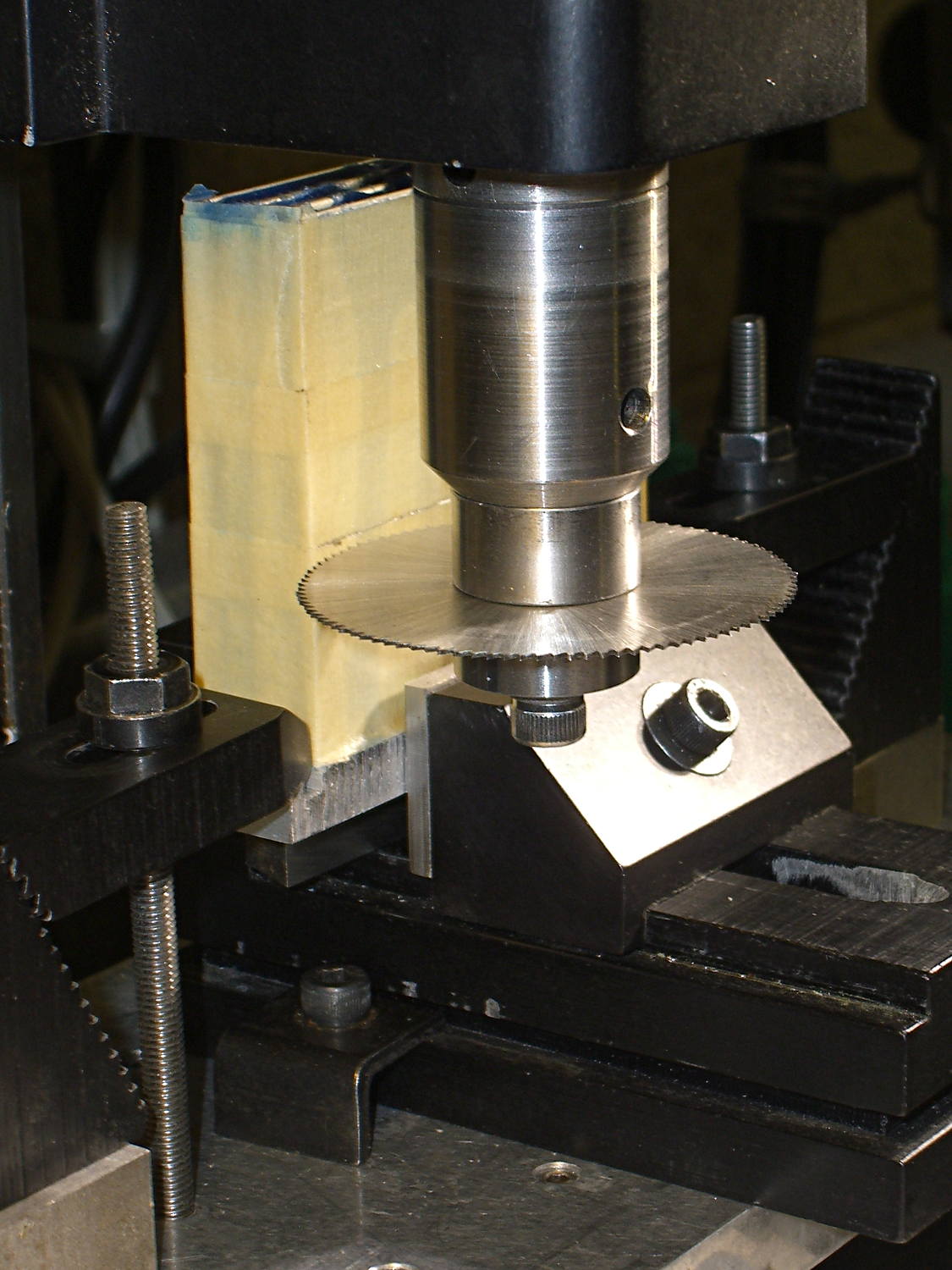
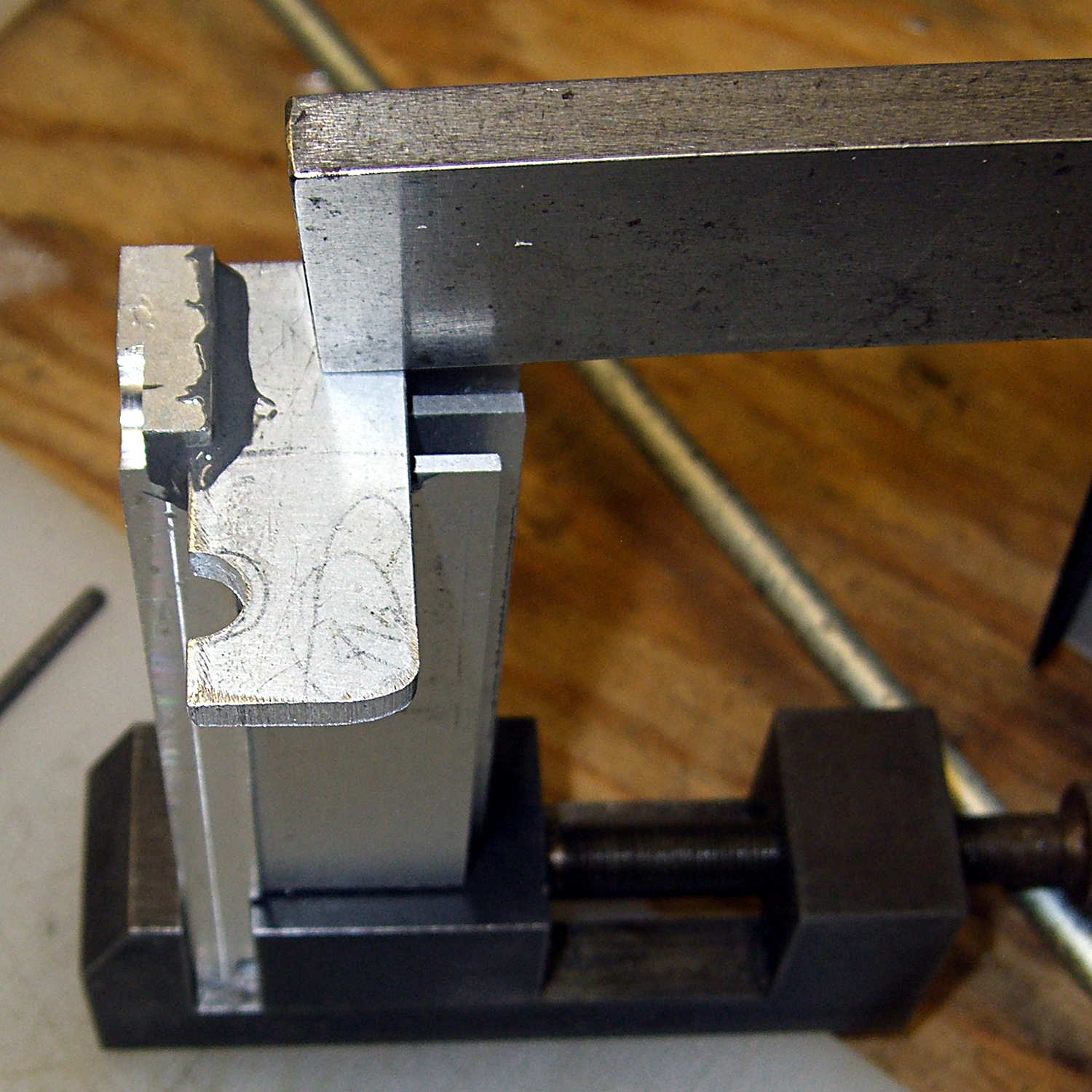
Clamped into the Sherline’s vise, it’s obvious that the slitting saw won’t quite reach all the way through:
Heatsink – slitting saw setup
I figured the height by working backwards from the outside of the end cap and forward from the bulkhead at the end of the arm. As it turned out, the middle fins fit and the outer two didn’t, but it was surprisingly close. The length turned out to be spot on, which is the sort of coincidence that tells me I’m on the right track. This is not an exact science.
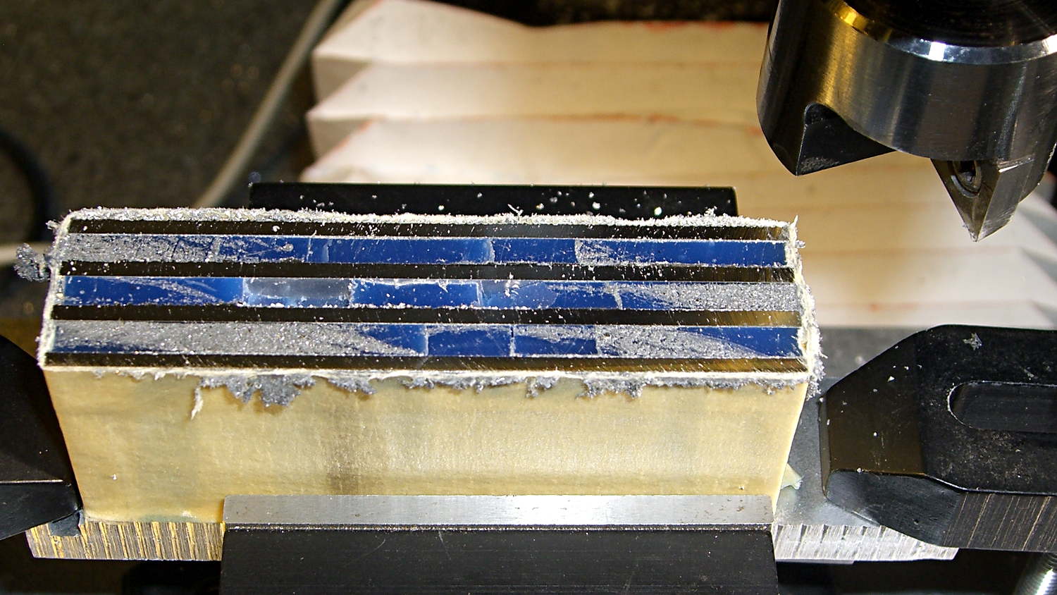
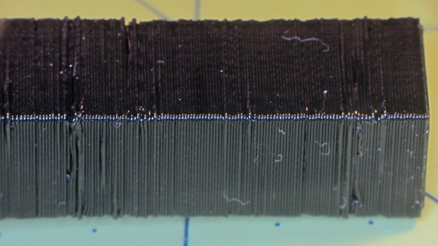
One cut along the front, another along the rear, and the fins popped right off:
Heatsink – cut detail
Those aren’t broken teeth on the blade, they’re just loaded with wax and aluminum dust.
My plan to secure the heatsink to the sewing machine by repurposing two convenient screws was foiled by the lower screw: it’s too short and sports a fine 6-40 thread. Not only does my heap lack 6-40 screws, Eks doesn’t have any, either; I would have lost big money on that bet.
Brownell’s has a fillister-head screw assortment including 6-40 threads, so that problem will Go Away in short order, but they’re out of stock at the moment. My other Brownell’s assortment (which they no longer carry) includes 5-40 screws, but …
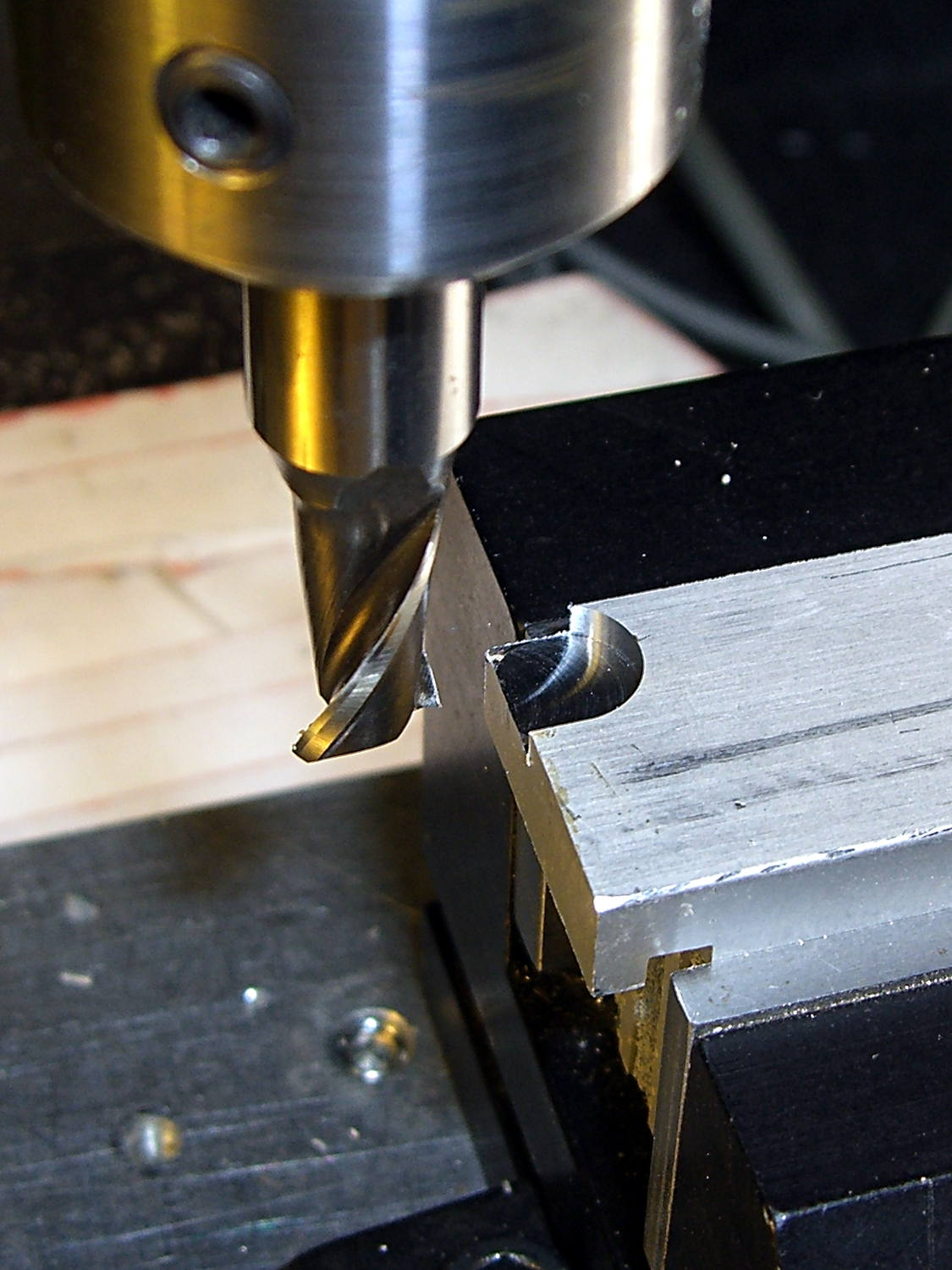
This being a prototype, I simply milled a recess to accommodate the offending screw head:
Heatsink – screw head clearance slot
The upper screw originally held the incandescent lamp socket in place and will be long enough to hold the heatsink.
In there somewhere, the ragged bandsawed edge on the far side got itself milled smooth.
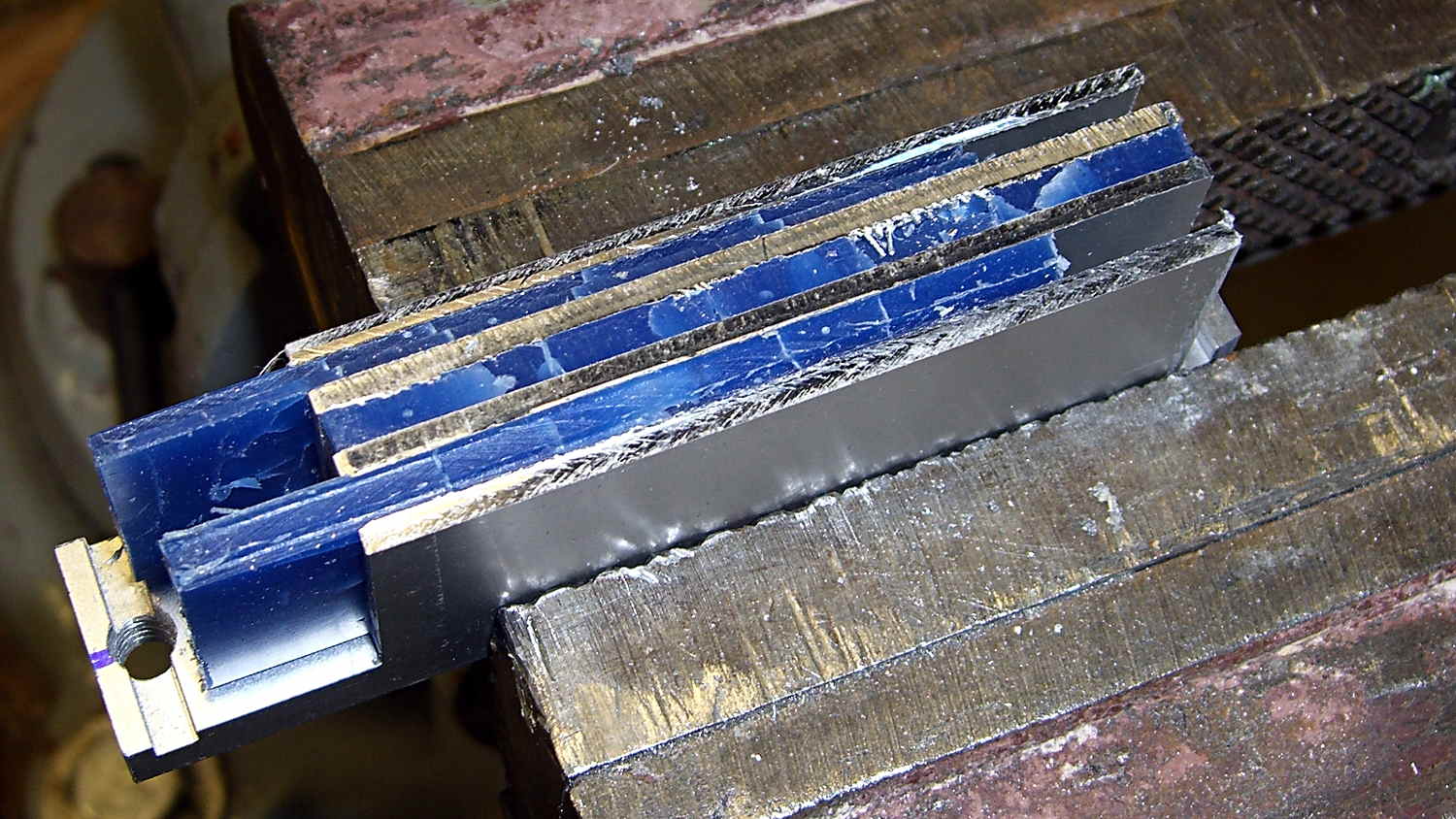
Some trial fitting showed the two outer fins must be 2 mm shorter to fit inside the end cap, so the finish on those isn’t nearly as nice:
Heatsink – removing machinable wax
That shows the machinable wax on its way out of the fins, urged along by whacking the ends with a wooden stick. The wax doesn’t adhere to the aluminum and leaves a clean surface, although I’m sure I should scrub it down with solvent to remove any residue.
A bit of paper-doll cutout work provided a shape for the plate that will hold the LEDs, then some bandsaw and hand-filing and milling trimmed it to fit. The heatsink has a slot along the edge, barely visible at the right end of the previous photo, so I hand-filed a rabbet in the plate to let it sit flat against the bottom of the slot and the end of the fins.
Steel-filled epoxy (good old JB Weld) secures the plate and provides good thermal transfer. The steel bar holds the plate against the fins while the epoxy cures:
Heatsink – epoxying LED mount
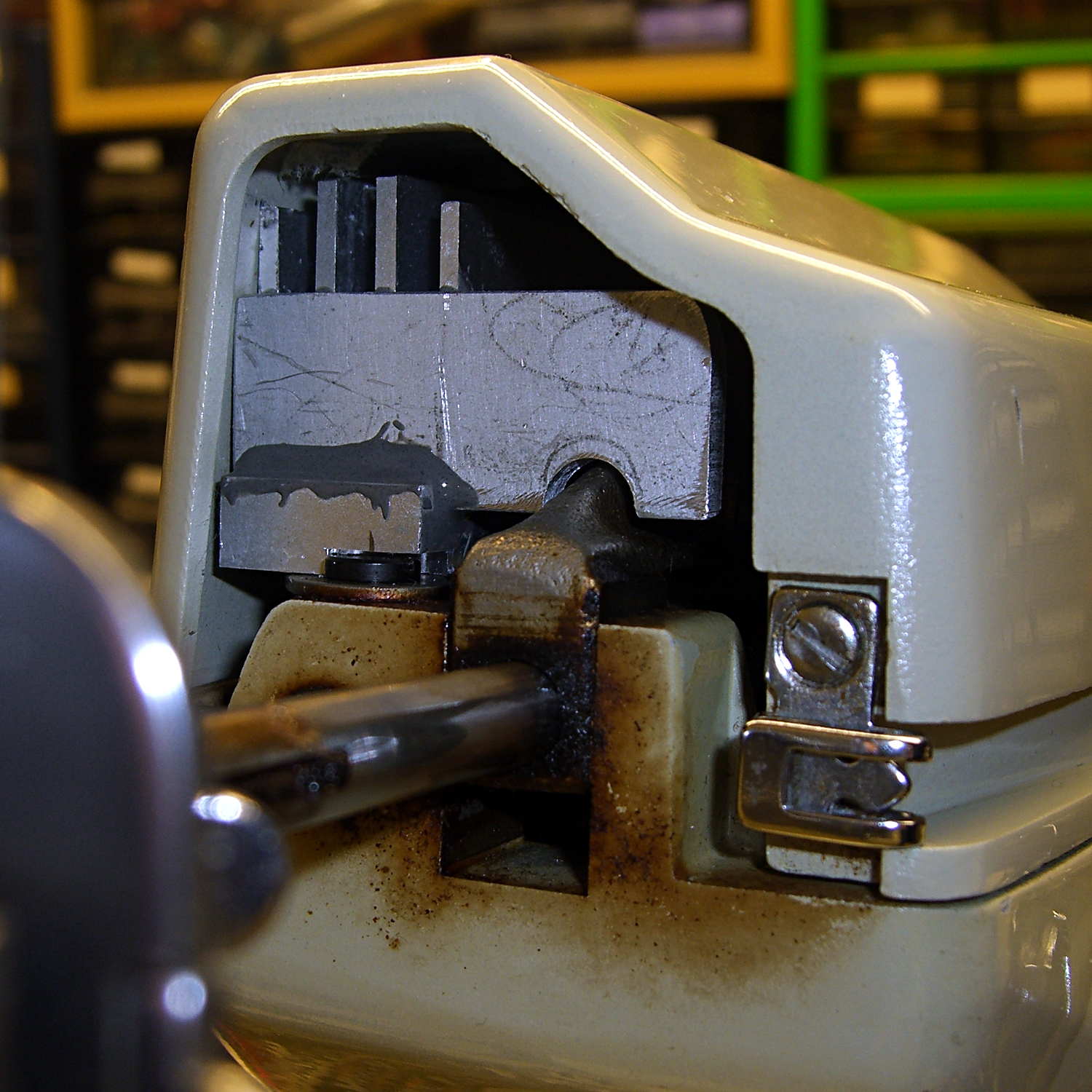
After some iterative abrasive adjustment on the belt sander, the assembly just barely fits inside the end cap. This view looks through the bobbin access hatch opening in the bed:
Heatsink – endcap trial fit
The two outer fins hit various mold sprues / vents / protrusions inside the cast (!) end cap. I think the next version will have three fins, as the cap rides right against the outer fin; the abrasive adjustment came into play on that fin and the end of the LED plate.
The plate could be a bit longer, but let’s see how this one works out.
The notch just barely clears the arm that moves the needle sideways during zig-zag stiches. The rectangular joint guides the arm left-to-right (vertically in this image), but doesn’t slide up-and-down. I think it’s as far out as it’ll ever get, but, again, this is a prototype.
Back when I started fiddling with 3D printed chain mail, the whole process from model to plastic worked wonderfully well. That continued with the larger sheets, but now, occasionally, the OpenSCAD model would produce weirdly sliced links. Depending on nothing repeatable, some links wouldn’t bridge correctly: the thread paths in the bottom layer across the gap would mysteriously stop just short of one pillar, return to the start, and leave an unsupported shelf that would, of course, fall into the gap.
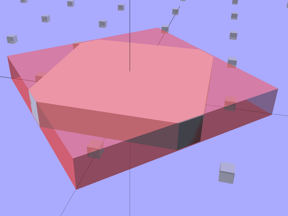
Shortly before Christmas, I managed to get a consistent failure that manifested differently: upon loading the STL file, Slic3r would quietly perform dozens of automatic corrections that (sometimes!) produced bizarrely distorted results. Feeding a failing model into Meshlab showed an irregular assortment of “self intersecting faces”, highlighted in red:
Chain Mail Square Armor – open – 2×2 – Meshlab self-intersecting faces
Although all four outer links in that image come from the same OpenSCAD module with identical sizes, they don’t all exhibit the same problem in the (nominally identical) faces on each of their four corners. In fact, those faces come from the intersection of two square slabs, carefully sized and positioned to avoid creating coincident planes:
Chain Mail Link – Outer shape
The central opening comes from a similar, slightly smaller, intersected-squares shape, but all four interior corner faces in each link show that they’re self-intersecting.
The STL looked fine in Meshlab, except for the highlit self-intersecting faces, so the geometry seemed OK.
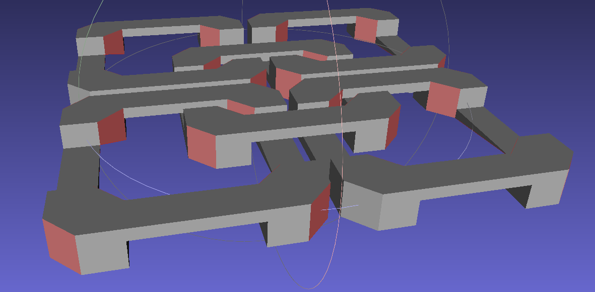
When Slic3r autocorrected the “problems”, it apparently removed one vertex on the bottom surface of each bar, deleted the triangles connected to that vertex, then repaired the mesh to produce a delightfully symmetric pattern:
Chain Mail Square Armor – open – 2×2 – Slic3r corrections
Although the links are resolutely symmetric, Slic3r seemed happy with the identical vertices at the other end of the bar.
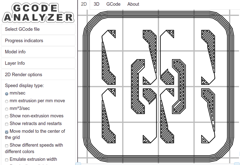
Unfortunately, the resulting G-Code won’t produce good links:
Chain Mail Square Armor – open – 2×2 – first layer G-code visualization
So, shortly before Christmas, I filed an issue on OpenSCAD’s Github repository.
The ensuing discussion showed that Meshlab flags faces as “self intersecting” when they have different vertices, even if their values are numerically equal, as well as vertices that differ by teeny amounts. Slic3r applies slightly different criteria to vertices & faces when it automagically corrects “problems” in the STL file, so that Meshlab may:
Highlight faces that don’t bother Slic3r
Apply the same highlight to faces that cause horrible problems
I don’t profess to understand much of that and may have the details wrong, but, apparently, OpenSCAD formerly used quantized coordinates that ensured all vertices within a tiny volume would have the same numeric value. In particular, all three faces that meet at a common point would, in fact, have numerically equal coordinate values for that point. The STL file format consists of a list of separate triangles, each with three coordinates for each of the three axes, and (without quantization) it was entirely possible for each of the three triangles with a common point to have three very slightly different positions for that point.
In theoretic terms, quantized coordinates cause horrible problems during geometric manipulation, because numeric values that aren’t exact can make repeated transformations come out wrong; running an object through a transformation and it’s inverse might not yield an object identical to the original one.
In practical terms, it seems that slicers and STL repair algorithms can reach incorrect conclusions based on minute differences produced by floating-point operations and numeric-to-text conversions. Those differences depend on slight changes in position, rotation, and size, so doing anything to the model produces completely different results.
That notwithstanding, the day after Christmas brought a new OpenSCAD version that uses quantized coordinates. A bit of rummaging in the source shows that the 3D grid (defined in src/grid.h) isn’t all that coarse:
const double GRID_FINE = 0.00000095367431640625;
STL files don’t carry units, so that could be in either millimeters (the Slic3r / RepRap convention) or inches (Sketchup, but we won’t go there). It’s exactly 1/10242, in case you were wondering, which produces a 5% speedup in the geometry engine compared to the more human-readable 1/10002.
With that commit in hand, all the chain mail links slice perfectly again.
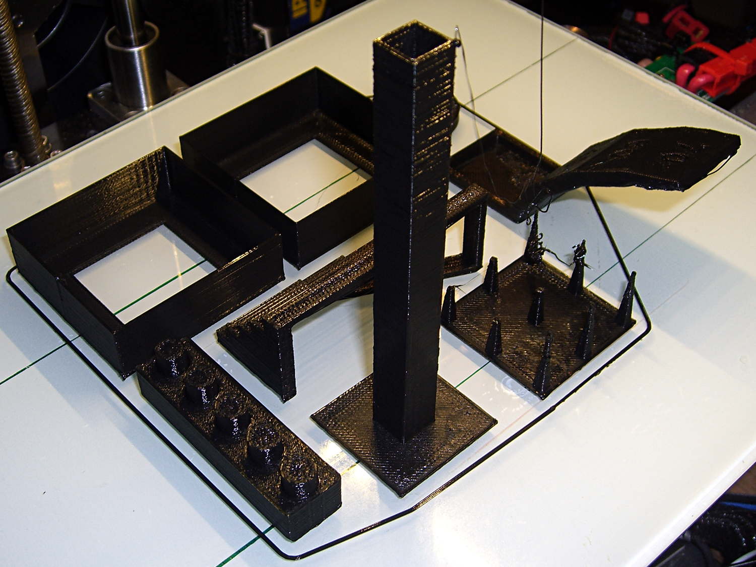
Just for completeness, here’s how the MAKE Magazine 2015 Test Objects came out on my somewhat modified MakerGear M2. I ignored the instructions, lumped all the models together, sliced ’em with my ordinary Slic3r settings, and printed the entire lot in one go:
MAKE Magazone 2015 Test Objects – on platform
Some details…
There’s no point in showing the Dimension Accuracy Tower-of-Hanoi (hiding behind the smokestack), as it looks exactly like it should. The 20 mm diameter platter came out at 19.7 ± 0.05 mm in both X and Y, so that’s a score of 2 or 3. It’s exactly the same along both axes, both diagonals, and, in fact, all the way around, within ±0.07 mm tolerance. In fact, all the layers worked out about that way; it’s consistently a bit too small. That’s what I’d expect for an uncalibrated model.
The Bridging Performance lattice gets a 5, with all the bars having dead-flat perimeters and no dropped infill. That would be a 1 if “dropped” should be “drooped”; I have no idea which is correct or exactly what they mean, but I have seen bridge threads drop off the sides, so I’ll assume it means what it says.
The front view shows the first bridging layer getting droopy under the longer bars, as you’d expect:
Bridging – front
All those drooping threads remain above the 2 mm tolerance, assuming that’s what they intended.
The bottom view shows the loose strands below the bars:
Bridging – bottom
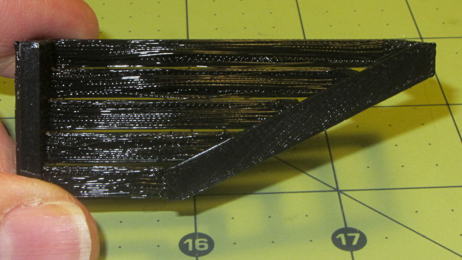
The Overhang Performance arch gets a 5, because the top surface finish remains pretty much the same from 30° through 70° overhang:
Overhang – upper
Underneath, things look weirder:
Overhang – lower
I think the oddness on the left (the underside of the 30° section) is due to interference from the Fine Positive Space Features spire array; the nozzle came directly from there. The 70° overhang looks ugly, but I wouldn’t have imagined that would work at all, let alone as well as it did.
The Negative Space Tolerance block weighs in at 2, as the pins with 0.6 and 0.5 mm clearance pushed out with finger pressure. The 0.3 and 0.4 mm clearance pins have air nearly all the way around, but would require a sharp rap from a mallet. The 0.2 mm pin remains firmly stuck:
Negative Space Tolerance
I don’t know how to judge the Fine Positive Space Features bed-o’-nails:
Fine Positive
I think it’s either a 2 or a 3, but opinions will certainly differ. Hot off the platform, five of the nine spires completed successfully. Three other got almost done, but broke off in handling. The collection of drool on the left-middle spire seems to be from the uncompleted spires in the foreground; I think there just wasn’t enough adhesion to hold them together. The perimeters ran at 50 mm/s and the infill at 150 mm/s, because it’s printed with everything else, so it wasn’t done with the delicacy it would get in isolation.
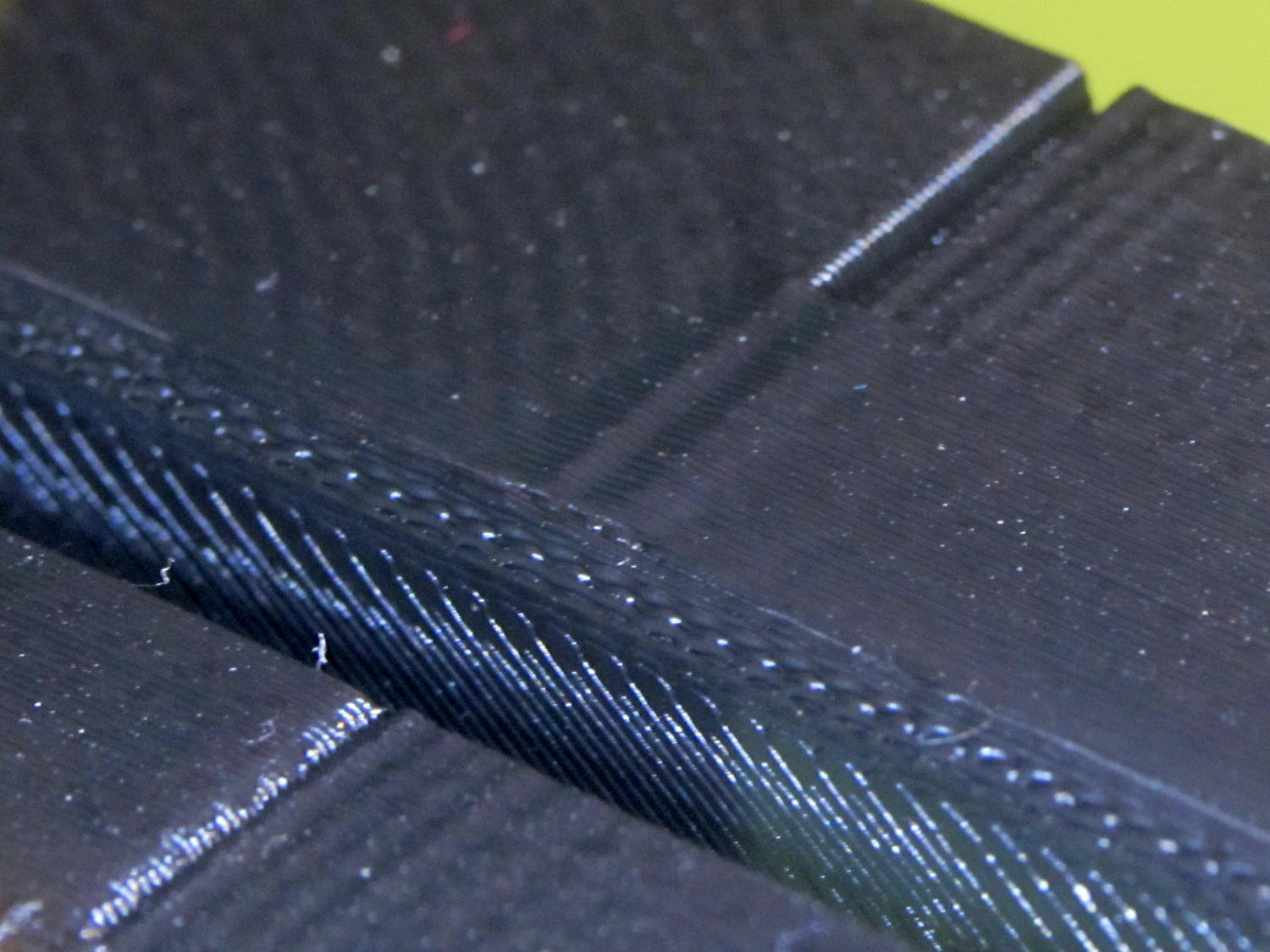
Both Mechanical Resonance in XY boxes look fine to me:
XY Resonance – notch
The ripples are visible, but barely perceptible to the thumbnail. The Rules call for 0 or 2, I’d give it a 1: if those ripples pose a problem, then sheesh you’re using the wrong process.
Also, the perimeters ran at 50 mm/s perimeter and the thick walls got 150 mm/s infill.
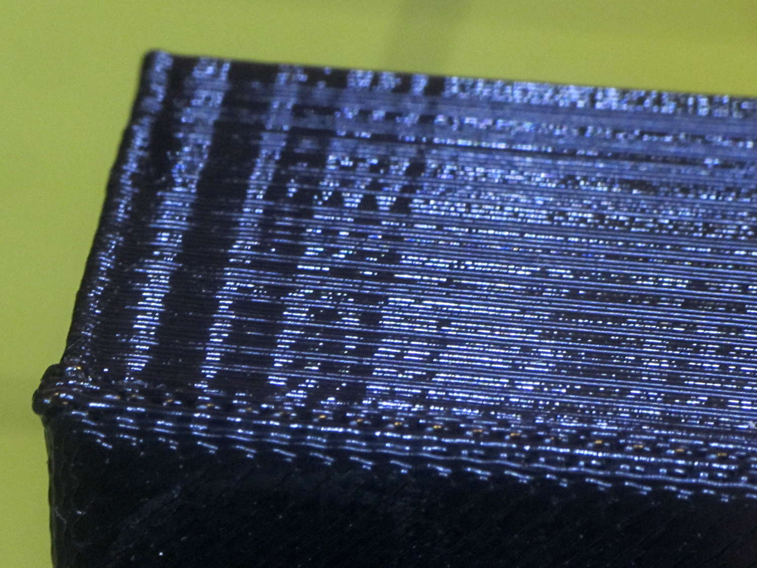
A corner of the single-wall box looks about the same as the corresponding point on the 1 mm box (which isn’t shown):
XY Resonance – corner
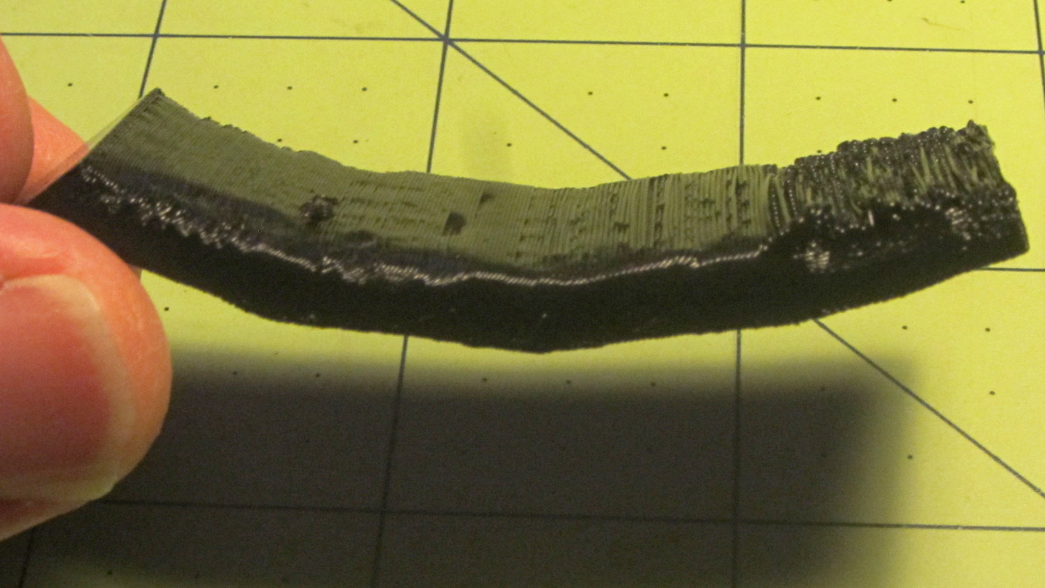
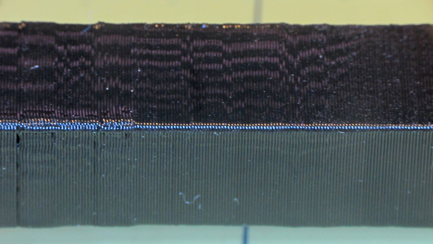
I think the Mechanical Resonance in Z smokestack gets a 1 (the Rules allow either 0 or 2); I stopped it after 100 mm, because bedtime. The bottom section shows the influence of all the other stuff going on around it:
Z Resonance – lower
That’s not a missed step over there on the far left: it lines up with the bottom bar of the adjacent Bridging Performance lattice. The next glitch lines up with the top of the Negative Space block. And so forth and so on.
The top, done all by itself at 11 mm/s, shows some misalignment:
Z Resonance – upper
Each layer took 15 seconds, so I suspect it’d look better with more cooling.
So, using ordinary default settings for everything and with all the handwaving in mind, I’ll call the total score 19-ish of a possible 29. The M2 would definitely do better on individual objects sliced with carefully hand-tuned parameters after considerable iteration; this is its ordinary, day-in-and-day-out performance on crazy models that I’d never attempt without tweaking.
The score would be much much much higher if I judged it with criteria similar to what I see applied to some of the Thingiverse groupings.
The M2 works well for me, anyhow.
For reference, here’s the current Slic3r configuration:
# generated by Slic3r 1.2.1 on Sun Dec 7 12:19:19 2014
avoid_crossing_perimeters = 0
bed_shape = -100x-125,100x-125,100x125,-100x125
bed_temperature = 70
bottom_solid_layers = 3
bridge_acceleration = 0
bridge_fan_speed = 100
bridge_flow_ratio = 1
bridge_speed = 150
brim_width = 0
complete_objects = 0
cooling = 1
default_acceleration = 0
disable_fan_first_layers = 1
dont_support_bridges = 1
duplicate_distance = 6
end_gcode = ;-- Slic3r End G-Code for M2 starts --\n; Ed Nisley KE4NZU - 15 November 2013\nM104 S0 ; drop extruder temperature\nM140 S0 ; drop bed temperature\nM106 S0 ; bed fan off\nG1 Z160 F2000 ; lower bed\nG1 X130 Y125 F30000 ; nozzle to right, bed front\nM84 ; disable motors\n;-- Slic3r End G-Code ends --
external_perimeter_extrusion_width = 0
external_perimeter_speed = 50
external_perimeters_first = 0
extra_perimeters = 1
extruder_clearance_height = 25
extruder_clearance_radius = 15
extruder_offset = 0x0
extrusion_axis = E
extrusion_multiplier = 1.07
extrusion_width = 0.4
fan_always_on = 0
fan_below_layer_time = 30
filament_diameter = 1.72
fill_angle = 45
fill_density = 20%
fill_pattern = 3dhoneycomb
first_layer_acceleration = 0
first_layer_bed_temperature = 70
first_layer_extrusion_width = 0.4
first_layer_height = 100%
first_layer_speed = 25
first_layer_temperature = 175
gap_fill_speed = 50
gcode_arcs = 0
gcode_comments = 0
gcode_flavor = reprap
infill_acceleration = 0
infill_every_layers = 2
infill_extruder = 1
infill_extrusion_width = 0
infill_first = 1
infill_only_where_needed = 0
infill_speed = 150
interface_shells = 0
layer_gcode =
layer_height = 0.2
max_fan_speed = 100
min_fan_speed = 75
min_print_speed = 4
min_skirt_length = 15
notes =
nozzle_diameter = 0.35
only_retract_when_crossing_perimeters = 1
ooze_prevention = 0
output_filename_format = [input_filename_base].gcode
overhangs = 1
perimeter_acceleration = 0
perimeter_extruder = 1
perimeter_extrusion_width = 0.4
perimeter_speed = 150
perimeters = 2
post_process =
raft_layers = 0
resolution = 0.01
retract_before_travel = 1
retract_layer_change = 0
retract_length = 1
retract_length_toolchange = 5
retract_lift = 0
retract_restart_extra = 0
retract_restart_extra_toolchange = 0
retract_speed = 60
seam_position = nearest
skirt_distance = 3
skirt_height = 1
skirts = 3
slowdown_below_layer_time = 10
small_perimeter_speed = 50
solid_fill_pattern = rectilinear
solid_infill_below_area = 5
solid_infill_every_layers = 0
solid_infill_extrusion_width = 0
solid_infill_speed = 150
spiral_vase = 0
standby_temperature_delta = -5
start_gcode = ;-- Slic3r Start G-Code for M2 starts --\n; Ed Nisley KE4NZU - 15 Nov 2013\n; 28 Feb 2014 - 6 Mar 2014 - tweak Z offset June July 2014\n; Z-min switch at platform, must move nozzle to X=130 to clear\nM140 S[first_layer_bed_temperature] ; start bed heating\nG90 ; absolute coordinates\nG21 ; millimeters\nM83 ; relative extrusion distance\nG92 Z0 ; set Z to zero, wherever it might be now\nG1 Z10 F1000 ; move platform downward to clear nozzle; may crash at bottom\nG28 Y0 ; home Y to be sure of clearing probe point\nG92 Y-127 ; set origin so 0 = center of plate\nG28 X0 ; home X\nG92 X-95 ; set origin so 0 = center of plate\nG1 X130 Y0 F30000 ; move off platform to right side, center Y\nG28 Z0 ; home Z with switch near center of platform\nG92 Z-4.65 ; set origin to measured z offset\nG0 Z2.0 ; get air under switch\nG0 Y-127 F10000 ; set up for priming, zig around corner\nG0 X0 ; center X\nM109 S[first_layer_temperature] ; set extruder temperature and wait\nM190 S[first_layer_bed_temperature] ; wait for bed to finish heating\nG1 Z0.0 F500 ; put extruder at plate \nG1 E30 F300 ; prime to get pressure, generate blob\nG1 Z5 F2000 ; rise above blob\nG1 X15 Y-125 F20000 ; jerk away from blob, move over surface\nG1 Z0.0 F1000 ; dab nozzle to attach outer snot to platform\nG4 P0.5 ; pause to attach\nG1 X35 F500 ; slowly smear snot to clear nozzle\nG1 Z1.0 F2000 ; clear bed for travel\n;-- Slic3r Start G-Code ends --
support_material = 0
support_material_angle = 0
support_material_enforce_layers = 0
support_material_extruder = 1
support_material_extrusion_width = 0
support_material_interface_extruder = 1
support_material_interface_layers = 3
support_material_interface_spacing = 0
support_material_interface_speed = 100%
support_material_pattern = pillars
support_material_spacing = 2.5
support_material_speed = 150
support_material_threshold = 0
temperature = 175
thin_walls = 1
threads = 2
toolchange_gcode =
top_infill_extrusion_width = 0
top_solid_infill_speed = 50
top_solid_layers = 3
travel_speed = 250
use_firmware_retraction = 0
use_relative_e_distances = 0
vibration_limit = 0
wipe = 0
xy_size_compensation = 0
z_offset = 0