The Smell of Molten Projects in the Morning

Ed Nisley's Blog: Shop notes, electronics, firmware, machinery, 3D printing, laser cuttery, and curiosities. Contents: 100% human thinking, 0% AI slop.

Tag: CNC

Making parts with mathematics

  • Hard Drive Platter Mood Light: 3D Printed Structure

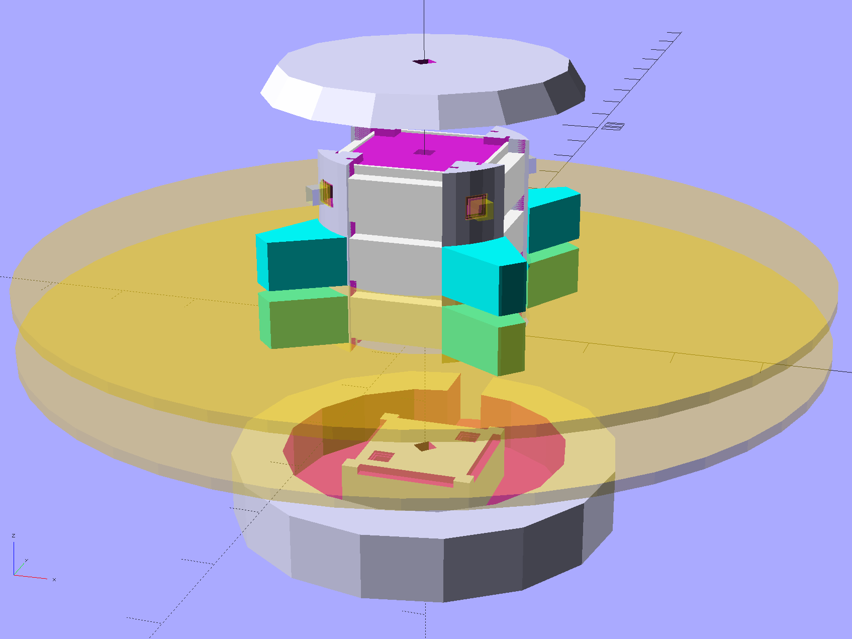
    Harvesting a stack of hard drive platters and discovering that four Neopixel strips could stand vertically inside the central hole suggested this overall structure:
    Hard Drive Mood Light - solid model - Show view
    Hard Drive Mood Light – solid model – Show view

    The model includes a parameter for the number of strips, but not everything respects that. I’m not sure I’ll ever make a three-LED column and five strips won’t fit, so it probably doesn’t matter.

    The central pillar holds everything together:

    Hard Drive Mood Light - solid model - Pillar
    Hard Drive Mood Light – solid model – Pillar

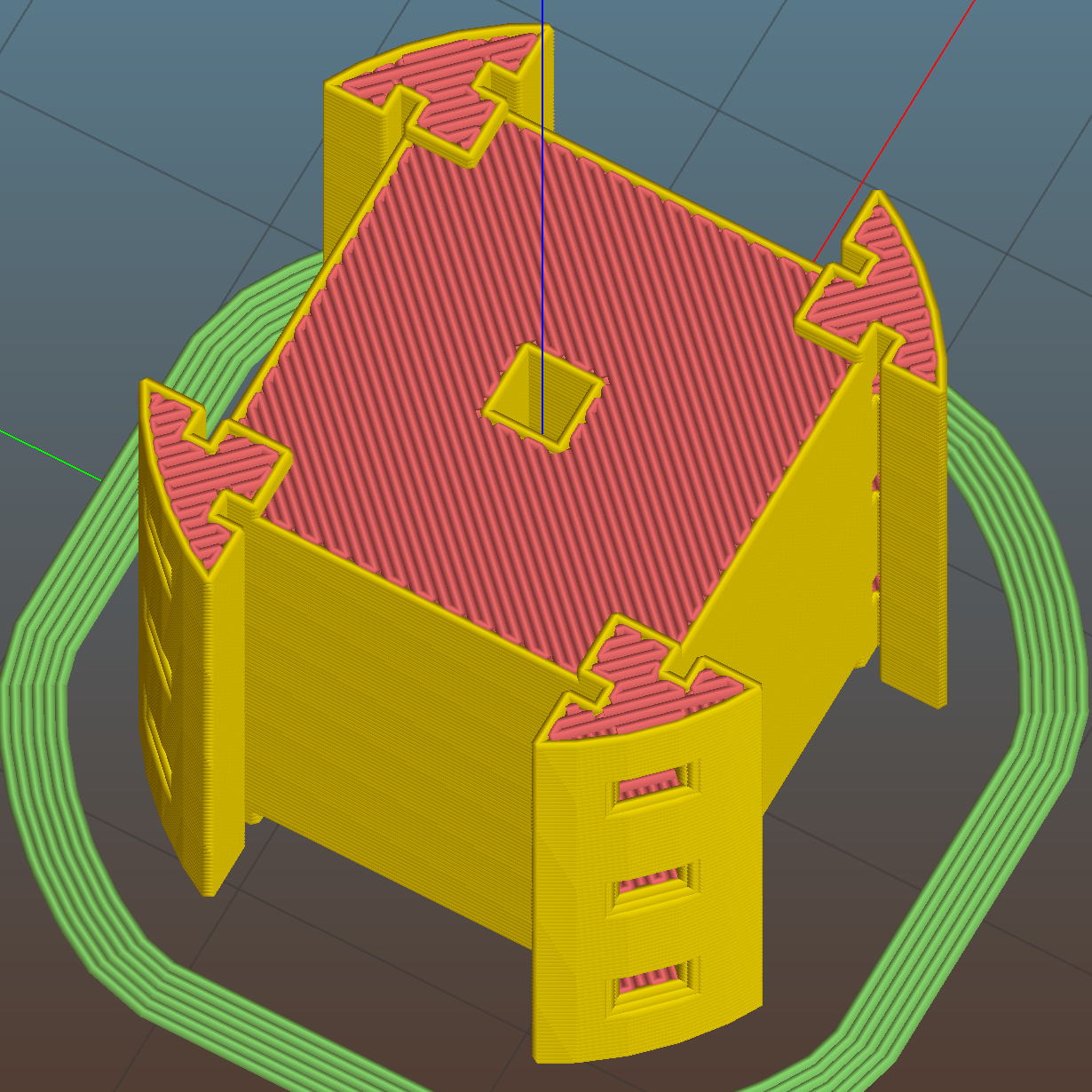
    The Neopixel strips slide into those slots, which turned out to be too small to actually print, because the molten plastic pretty much squeezed the slots closed. Some deft pull saw action enlarged them enough to pass the strips, at the cost of tedious hand-fitting and considerable hidden ugliness. Printing the slots slightly larger bangs against the (lack of) printer resolution, because there’s not much wiggle room between the tiny slots and the outer diameter of the column:
    Hard Drive Mood Light - Pillar - Slic3r preview
    Hard Drive Mood Light – Pillar – Slic3r preview

    The three alignment pin holes along each edge sit 6.944 mm on center, which is what you get when you divide the nominal 1 meter strip length by 144 Neopixels. I’m using knockoff Neopixels from halfway around the planet, but they’re probably pretty close to the real thing (also from halfway around the planet, I’m sure).

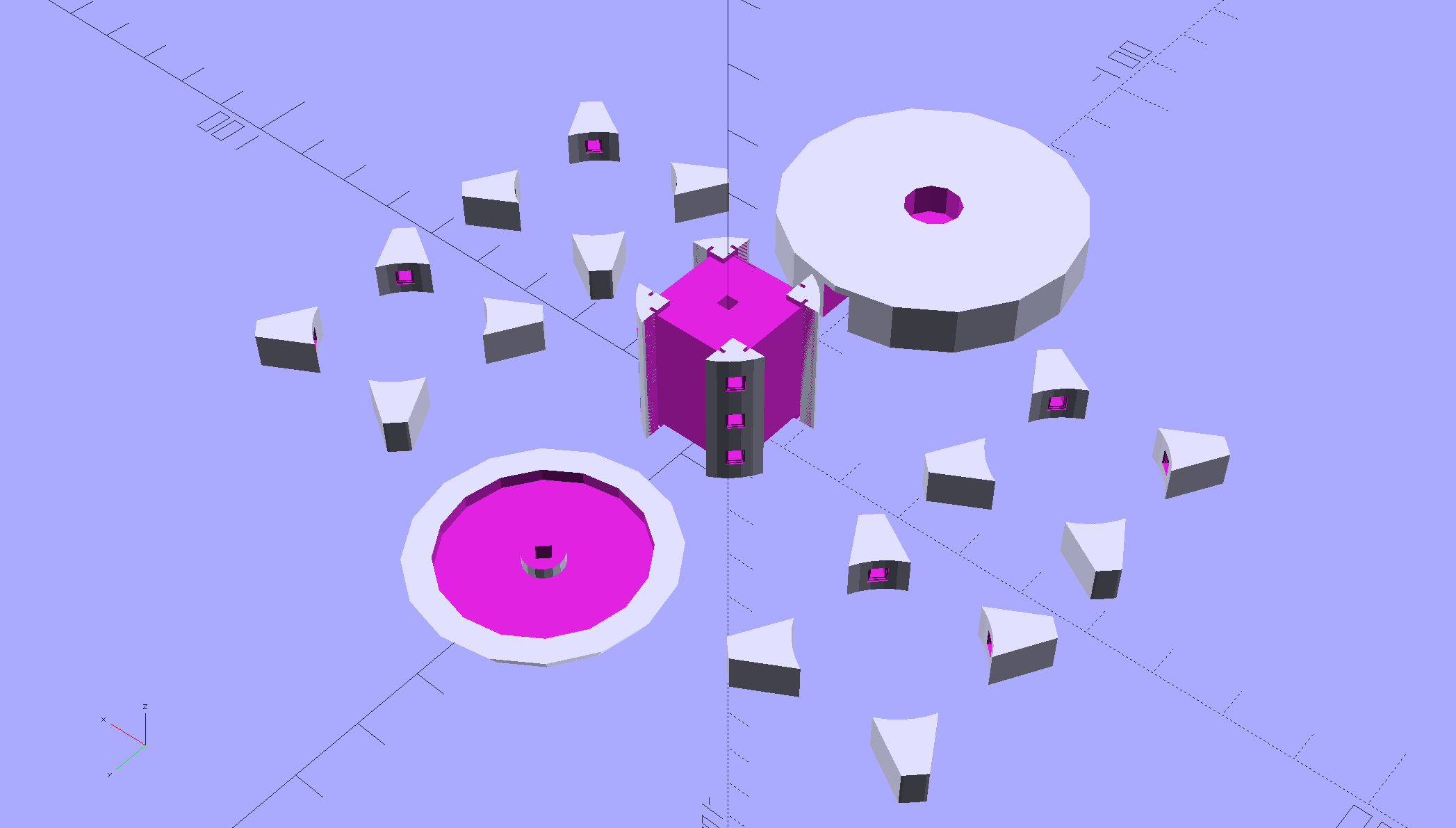
    All those parts laid out on the platform, along with a fourth set of spacers in case I drop one:
    Hard Drive Mood Light - solid model - Build view
    Hard Drive Mood Light – solid model – Build view

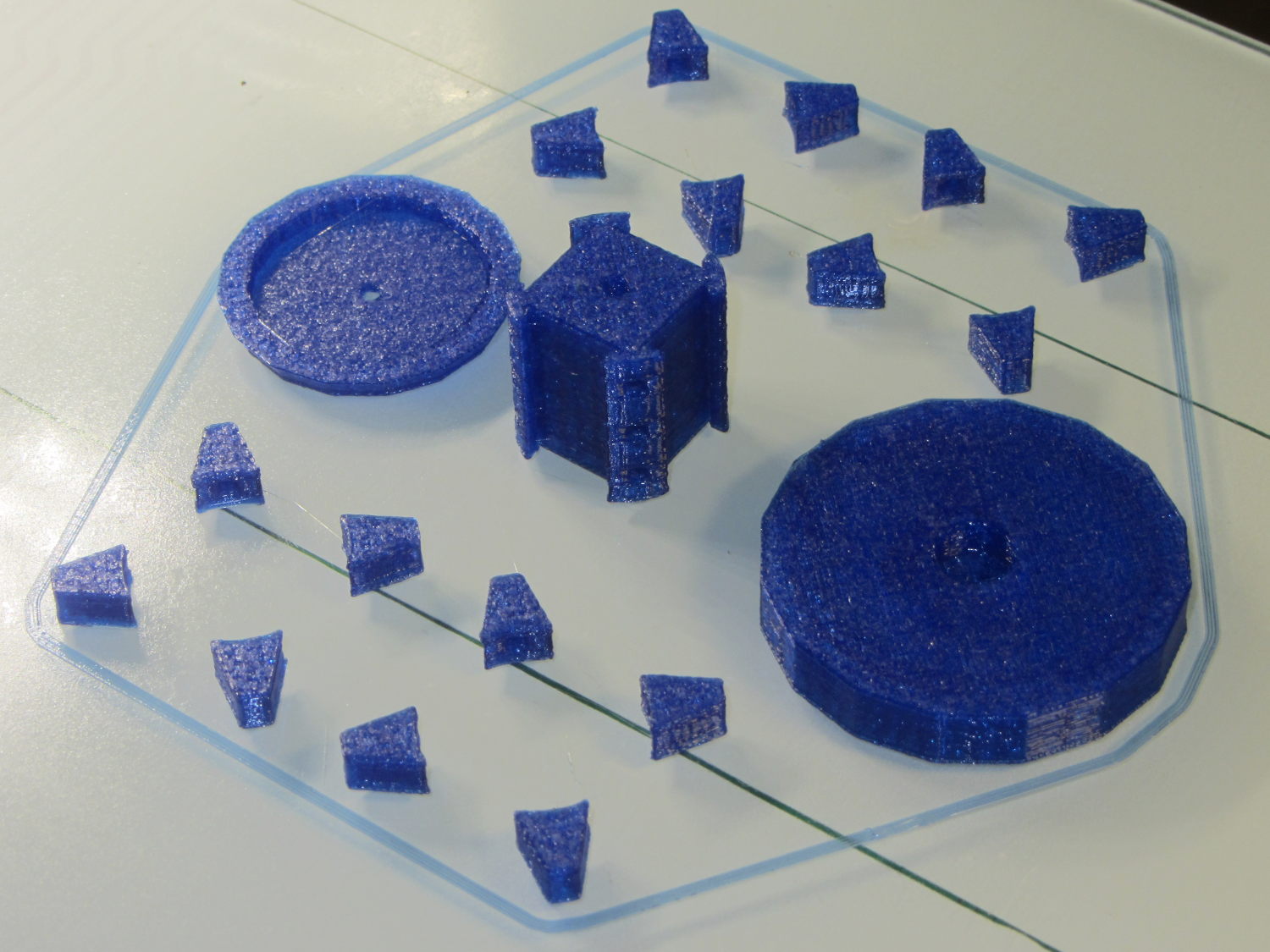
    And they print in cyan PETG just like you’d expect:
    Hard Drive Mood Light - parts on platform
    Hard Drive Mood Light – parts on platform

    The round base (on the right) prints bottom-side-up, with bridging from the rim to the central pillar, and came out looking just fine. The top doesn’t have the central post and the pillar doesn’t have the top recess shown in the model: those tweaks will appear in the next iteration.

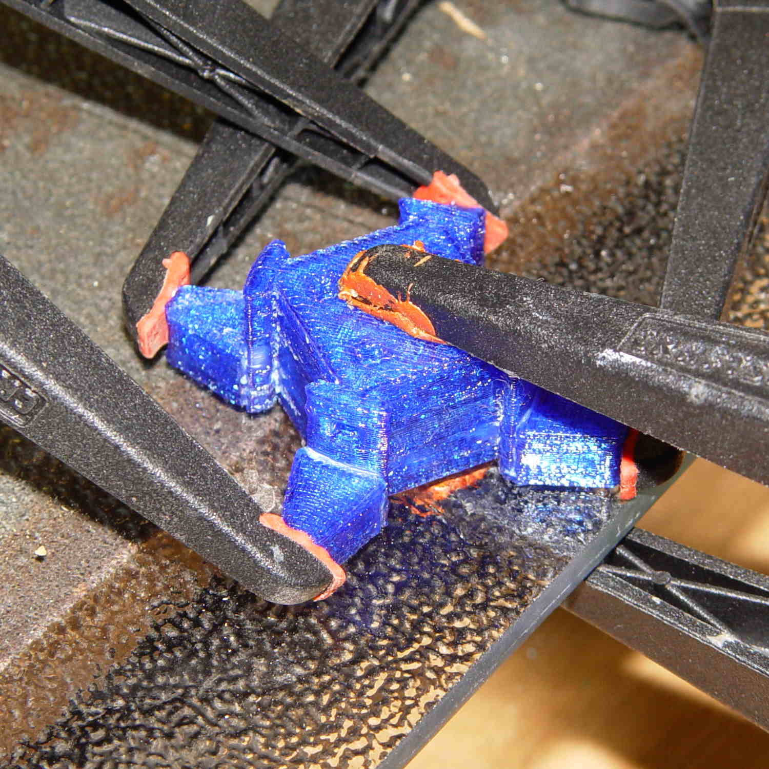
    Each tiny triangular spacer gets an alignment pin glued into its inner surface, then four of them get glued to the pillar. This crash test dummy pillar worked out the dimensions, so it’s squat and ugly:
    Hard Drive Platter Mood Light - pillar gluing
    Hard Drive Platter Mood Light – pillar gluing

    It’s clamped to a glass plate (smooth side up!) to force the spacers onto on a plane, with the other clamps smashing them against the pillar. All the other spacers get glued in situ atop each platter as it’s installed, which is a definite downside.

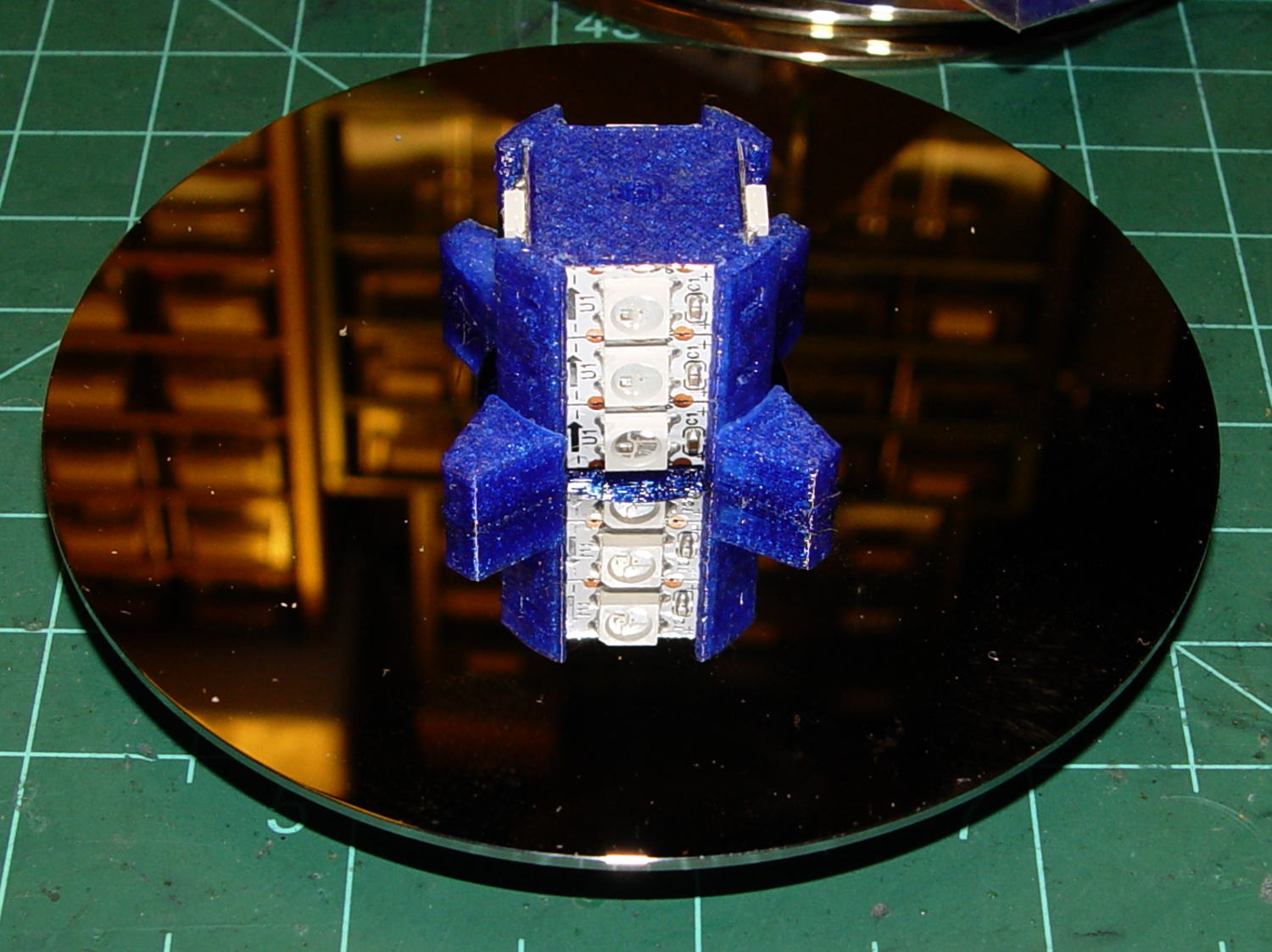
    Installing the Neopixels before assembling the platters seemed to be the right way to go:
    Hard Drive Mood Light - first platter assembly
    Hard Drive Mood Light – first platter assembly

    After that, just stack ’em up:

    Hard Drive Mood Light - top Neopixels
    Hard Drive Mood Light – top Neopixels

    I dry-assembled the upper two spacer sets, so I could pull it apart in case that seemed necessary. Turned out to be a good idea.

    And then screw the lid on top to see what it looks like:

    Hard Drive Mood Light - trial assembly
    Hard Drive Mood Light – trial assembly

    That top screw should be a pan-head or something similarly smooth, rather than a random PC case screw. The sacrificial hard drives provided a bunch of Torx screws that would surely look better; most are far too small.

    I thought a taller stack would be appropriate, but I kinda like the short, squat aspect ratio.

    Now for some wiring…

    The OpenSCAD source code:

    // Hard Drive Platter Mood Light
    // Ed Nisley KE4ZNU November 2015
    
    Layout = "Show";					// Build Show Pixel LEDString Platters Pillar Spacers TopCap Base
    
    ShowDisks = 2;						// number of disks in Show layout
    
    //- Extrusion parameters must match reality!
    
    ThreadThick = 0.20;
    ThreadWidth = 0.40;
    
    HoleWindage = 0.2;
    
    Protrusion = 0.1;			// make holes end cleanly
    
    inch = 25.4;
    
    function IntegerMultiple(Size,Unit) = Unit * ceil(Size / Unit);
    
    //----------------------
    // Dimensions
    
    ID = 0;
    OD = 1;
    LENGTH = 2;
    
    Platter = [25.0,95.0,1.27];						// hard drive platters
    
    LEDStringCount = 3;								// number of LEDs on each strip (Show mode looks odd for less than 3)
    LEDStripCount = 4;								// number of strips (verify locating pin holes & suchlike)
    
    WireSpace = 1.0;								// allowance for wiring along strip ends
    
    BaseSize = [40,14,3.0];							// overall base plate outside engine controller slot
    
    Pixel = [13.0, 1000 / 144, 0.5];				// smallest indivisible unit of LED strip
    PixelMargin = [1.0, 1.0, 2.0];					// LED and circuitry atop the strip
    
    BeamAngle = 120;								// LED viewing angle
    BeamShape = [
    	[0,0],
    	[Platter[OD]*cos(BeamAngle/2),-Platter[OD]*sin(BeamAngle/2)],
    	[Platter[OD]*cos(BeamAngle/2), Platter[OD]*sin(BeamAngle/2)]
    ];
    
    PillarSides = 12*4;
    
    PillarCore = Platter[ID] - 2*(Pixel[2] + PixelMargin[2] + 2.0);		// LED channel distance across pillar centerline
    PillarLength = LEDStringCount*Pixel[1] + Platter[LENGTH];
    echo(str("Pillar core size: ",PillarCore));
    echo(str("      ... length:"),PillarLength);
    
    Cap = [Platter[ID] + 4.0,Platter[ID] + 4.0 + 10*2*ThreadWidth,2*WireSpace + 6*ThreadThick];		// cap over top of pillar
    CapSides = 16;
    
    Base = [Platter[ID] + 10.0,0.5*Platter[OD],8.0];
    BaseSides = 16;
    
    Screw = [2.0,3.0,20.0];							// screws used to secure cap & pillar
    
    Spacer = [Platter[ID],(Platter[ID] + 2*8),(Pixel[1] - Platter[LENGTH])];
    echo(str("Spacer  OD: ",Spacer[OD]));
    echo(str(" ... thick:",Spacer[LENGTH]));
    
    LEDStripProfile = [
    	[0,0],
    	[Pixel[0]/2,0],
    	[Pixel[0]/2,Pixel[2]],
    	[(Pixel[0]/2 - PixelMargin[0]),Pixel[2]],
    	[(Pixel[0]/2 - PixelMargin[0]),(Pixel[2] + PixelMargin[2])],
    	[-(Pixel[0]/2 - PixelMargin[0]),(Pixel[2] + PixelMargin[2])],
    	[-(Pixel[0]/2 - PixelMargin[0]),Pixel[2]],
    	[-Pixel[0]/2,Pixel[2]],
    	[-Pixel[0]/2,0]
    ];
    
    //----------------------
    // Useful routines
    
    module PolyCyl(Dia,Height,ForceSides=0) {			// based on nophead's polyholes
    
      Sides = (ForceSides != 0) ? ForceSides : (ceil(Dia) + 2);
    
      FixDia = Dia / cos(180/Sides);
    
      cylinder(r=(FixDia + HoleWindage)/2,
    		h=Height,
    	$fn=Sides);
    }
    
    //- Locating pin hole with glue recess
    //  Default length is two pin diameters on each side of the split
    
    PinOD = 1.70;
    
    module LocatingPin(Dia=PinOD,Len=0.0) {
    	
    	PinLen = (Len != 0.0) ? Len : (4*Dia);
    	
    	translate([0,0,-ThreadThick])
    		PolyCyl((Dia + 2*ThreadWidth),2*ThreadThick,4);
    
    	translate([0,0,-2*ThreadThick])
    		PolyCyl((Dia + 1*ThreadWidth),4*ThreadThick,4);
    		
    	translate([0,0,-(PinLen/2 + ThreadThick)])
    		PolyCyl(Dia,(PinLen + 2*ThreadThick),4);
    
    }
    //----------------------
    // Pieces
    
    //-- LED strips
    
    module OnePixel() {
    	
    	render()
    		rotate([-90,0,0]) rotate(180)				// align result the way you'd expect from the dimensions
    			difference() {
    				linear_extrude(height=Pixel[1],convexity=3)
    					polygon(points=LEDStripProfile);
    				translate([-Pixel[0]/2,Pixel[2],-PixelMargin[0]])
    					cube([Pixel[0],2*PixelMargin[2],2*PixelMargin[0]]);
    				translate([-Pixel[0]/2,Pixel[2],Pixel[1]-PixelMargin[0]])
    					cube([Pixel[0],2*PixelMargin[2],2*PixelMargin[0]]);
    			}
    }
    
    module LEDString(n = LEDStringCount) {
    	
    	for (i=[0:n-1])
    		translate([0,i*Pixel[1]])
    //			resize([0,Pixel[1] + 2*Protrusion,0])
    				OnePixel();
    }
    
    //-- Stack of hard drive platters
    
    module Platters(n = LEDStringCount + 1) {
    	
    	color("gold",0.4)
    	for (i=[0:n-1]) {
    		translate([0,0,i*Pixel[1]])
    			difference() {
    				cylinder(d=Platter[OD],h=Platter[LENGTH],center=false,$fn=PillarSides);
    				cylinder(d=Platter[ID],h=3*Platter[LENGTH],center=true,$fn=PillarSides);
    			}
    	}
    }
    
    //-- Pillar holding the LED strips
    
    module Pillar() {
    	
    	difflen = PillarLength + 2*Protrusion;
    	
    //	render(convexity=5)
    	difference() {
    		linear_extrude(height=PillarLength,convexity=4)
    			difference() {
    				rotate(180/(12*4))
    					circle(d=Platter[ID] - 1*ThreadWidth,$fn=PillarSides);
    				
    				for (i=[0:LEDStripCount-1]) 					// clearance for LED beamwidth, may not actually cut surface
    					rotate(i*360/LEDStripCount)
    						translate([PillarCore/2,0,0])
    							polygon(points=BeamShape);
    							
    				for (i=[0:LEDStripCount-1])						// LED front clearance
    					rotate(i*360/LEDStripCount)
    						translate([(PillarCore/2 + Pixel[2]),(Pixel[0] - 2*PixelMargin[0])/2])
    							rotate(-90)
    								square([Pixel[0] - 2*PixelMargin[0],Platter[ID]]);
    
    			}
    			
    		for (i=[0:LEDStripCount-1])								// LED strip slots
    			rotate(i*360/LEDStripCount)
    				translate([PillarCore/2,0,-Protrusion])
    					linear_extrude(height=difflen,convexity=2)
    						rotate(-90)
    							polygon(points=LEDStripProfile);
    		
    		for (i=[0,90])											// wiring recess on top surface
    			rotate(i)
    				translate([0,0,(PillarLength - (WireSpace/2 - Protrusion))])
    					cube([(PillarCore + 2*Protrusion),Pixel[0] - 2*PixelMargin[0],WireSpace],center=true);
    							
    		for (i=[0:LEDStripCount-1])								// wiring recess on bottom surface
    			rotate(i*90)
    				translate([PillarCore/2 - (WireSpace - Protrusion)/2,0,WireSpace/2 - Protrusion])
    					cube([WireSpace + Protrusion,Pixel[0] - 2*PixelMargin[0],WireSpace],center=true);
    							
    		for (j=[0:LEDStringCount-1])							// platter spacer alignment pins
    			for (i=[0:LEDStripCount-1])
    				rotate(i*360/LEDStripCount + 180/LEDStripCount)
    					translate([(Platter[ID] - 1*ThreadWidth)/2,0,(j*Pixel[1] + Pixel[1]/2 + Platter[LENGTH]/2)])
    						rotate([0,90,0])
    							rotate(45)
    								LocatingPin();
    								
    		translate([0,0,-Protrusion])							// central screw hole
    			rotate(180/4)
    				PolyCyl(Screw[ID],difflen,4);
    		
    		if (false)
    		for (i=[-1,1])											// vertical wire channels
    			rotate(i*360/LEDStripCount + 180/LEDStripCount)
    				translate([PillarCore/2 - 2.0,0,-Protrusion])
    					PolyCyl(2.0,difflen,4);
    					
    		for (i=[-1,1])											// locating pins
    			rotate(i*360/LEDStripCount - 180/LEDStripCount)
    				translate([PillarCore/2 - 2.0,0,0])
    					LocatingPin();
    	}
    }
    
    //-- Spacers to separate platters
    
    module Spacers() {
    
    	difference() {
    		linear_extrude(height=Spacer[LENGTH],convexity=4)
    			difference() {
    				rotate(180/PillarSides)
    					circle(d=Spacer[OD],$fn=PillarSides);
    				
    				for (i=[0:LEDStripCount-1]) 					// clearance for LED beamwidth, may not actually cut surface
    					rotate(i*360/LEDStripCount)
    						translate([PillarCore/2,0,0])
    							polygon(points=BeamShape);
    							
    				for (i=[0:LEDStripCount-1])						// LED front clearance
    					rotate(i*360/LEDStripCount)
    						translate([(PillarCore/2 + Pixel[2]),(Pixel[0] - 2*PixelMargin[0])/2])
    							rotate(-90)
    								square([Pixel[0] - 2*PixelMargin[0],Platter[ID]]);
    
    							
    				rotate(180/PillarSides)
    					circle(d=Spacer[ID],$fn=PillarSides);		// central pillar fits in the hole
    			}
    			
    		for (i=[0:LEDStripCount-1])
    			rotate(i*360/LEDStripCount + 180/LEDStripCount)
    				translate([Platter[ID]/2,0,(Pixel[1] - Platter[LENGTH])/2])
    					rotate([0,90,0])
    						rotate(45)
    							LocatingPin();
    
    	}
    }
    
    //-- Cap over top of pillar
    
    module TopCap() {
    	
    	difference() {
    		cylinder(d1=(Cap[OD] + Cap[ID])/2,d2=Cap[OD],h=Cap[LENGTH],$fn=CapSides);		// outer lid
    		
    		translate([0,0,-Protrusion])
    			PolyCyl(Screw[ID],Cap[LENGTH] + WireSpace + Protrusion,4);					// screw hole
    		
    		translate([0,0,Cap[LENGTH] - 2*WireSpace])
    			difference() {
    				cylinder(d=Cap[ID],h=2*Cap[LENGTH],$fn=CapSides);						// cutout
    				cylinder(d=2*Screw[OD],h=Cap[LENGTH],$fn=CapSides);						// boss
    			}
    		
    		translate([0,0,Cap[LENGTH] - ThreadThick])
    			cylinder(d=Cap[ID]/2,h=ThreadThick + Protrusion,$fn=CapSides);				// recess boss
    	}
    }
    
    //-- Base below pillar
    
    module Base() {
    	
    	SideWidth = 0.5*Base[OD]*sin(180/BaseSides);						// close enough
    	
    	difference() {
    		union() {
    			difference() {
    				cylinder(d=Base[OD],h=Base[LENGTH],$fn=BaseSides);			// outer base
    
    				translate([0,0,6*ThreadThick])								// main cutout
    					cylinder(d=Base[ID],h=Base[LENGTH],$fn=BaseSides);
    					
    				translate([-SideWidth/2,0,6*ThreadThick]) 					// cable port
    					cube([SideWidth,Base[OD],Base[LENGTH]]);
    			}
    			
    			translate([0,0,Base[LENGTH]/2])									// pillar support is recessed below rim
    				cube([PillarCore,PillarCore,Base[LENGTH] - ThreadThick],center=true);
    		}
    
    		for (i=[0:LEDStripCount-1])											// wiring recesses
    			rotate(i*90)
    				translate([PillarCore/2 - (WireSpace - Protrusion)/2,0,Base[LENGTH] - WireSpace/2])
    					cube([WireSpace + Protrusion,PillarCore - 4*WireSpace,WireSpace],center=true);
    		
    		translate([0,0,-Protrusion])
    			PolyCyl(Screw[ID],2*Base[LENGTH],4);						// screw hole
    			
    		translate([0,0,-Protrusion])									// screw head recess
    			PolyCyl(8.5,5.0 + Protrusion,$fn=6);
    			
    		for (i=[-1,1])													// locating pins
    			rotate(i*360/LEDStripCount - 180/LEDStripCount)
    				translate([PillarCore/2 - 2.0,0,Base[LENGTH] - ThreadThick])
    					LocatingPin();
    
    	}
    		
    }
    
    //----------------------
    // Build it
    
    if (Layout == "Pixel")
    	OnePixel();
    	
    if (Layout == "LEDString")
    	LEDString(LEDStringCount);
    	
    if (Layout == "Platters")
    	Platters(LEDStringCount + 1);
    	
    if (Layout == "Pillar")
    	Pillar(LEDStringCount);
    	
    if (Layout == "TopCap")
    	TopCap();
    		
    if (Layout == "Base")
    	Base();
    
    if (Layout == "Spacers")
    	Spacers();
    	
    if (Layout == "Show") {
    	Pillar();
    
    	for (i=[0:LEDStripCount-1])											// LED strips
    		rotate(i*360/LEDStripCount)
    			translate([PillarCore/2,0,Platter[LENGTH]/2])
    				rotate([90,0,90])
    					color("lightblue") LEDString();
    	if (true)	
    	for (j=[0:max(1,ShowDisks - 2)])									// spacers
    		translate([0,0,(j*Pixel[1] + Platter[LENGTH])])
    			color("cyan") Spacers();
    							
    	for (j=[0:max(2,ShowDisks - 2)])										// spacer alignment pins
    		for (i=[0:LEDStripCount-1])
    			rotate(i*360/LEDStripCount + 180/LEDStripCount)
    				translate([(Platter[ID] - 1*ThreadWidth)/2,0,(j*Pixel[1] + Pixel[1]/2 + Platter[LENGTH]/2)])
    					rotate([0,90,0])
    						rotate(45)
    							 color("Yellow",0.25) LocatingPin(Len=4);
    	translate([0,0,PillarLength + 3*Cap[LENGTH]])
    		rotate([180,0,0])
    			TopCap();
    	
    	translate([0,0,-3*Base[LENGTH]])
    		Base();
    		
    	if (ShowDisks > 0)	
    		Platters(ShowDisks);
    	
    }
    
    // Ad-hoc build layout
    
    if (Layout == "Build") {
    	Pillar();
    	
    	translate([0,Cap[OD],0])
    		TopCap();
    	
    	translate([0,-Base[OD],Base[LENGTH]])
    		rotate([0,180,0])
    			Base();
    	
    	Ybase = Spacer[OD] * (LEDStringCount%2 ? (LEDStringCount - 1) : (LEDStringCount - 2)) / 4;
    	for (i=[0:LEDStringCount])										// build one extra set of spacers!
    		translate([(i%2 ? 1 : -1)*(Spacer[OD] + Base[OD])/2,		// alternate X sides to shrink Y space
    				   (i%2 ? i-1 : i)*Spacer[OD]/2 - Ybase,			// same Y for even-odd pairs in X
    				   0])
    			Spacers();
    }
    

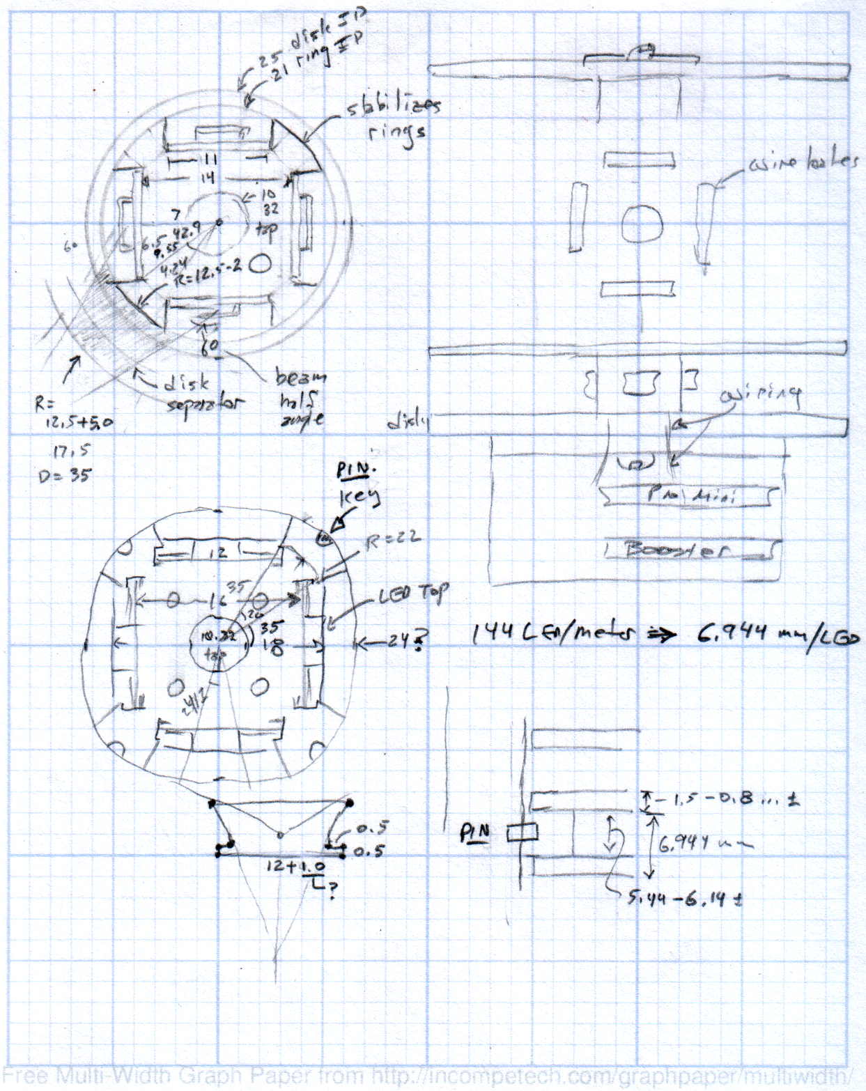
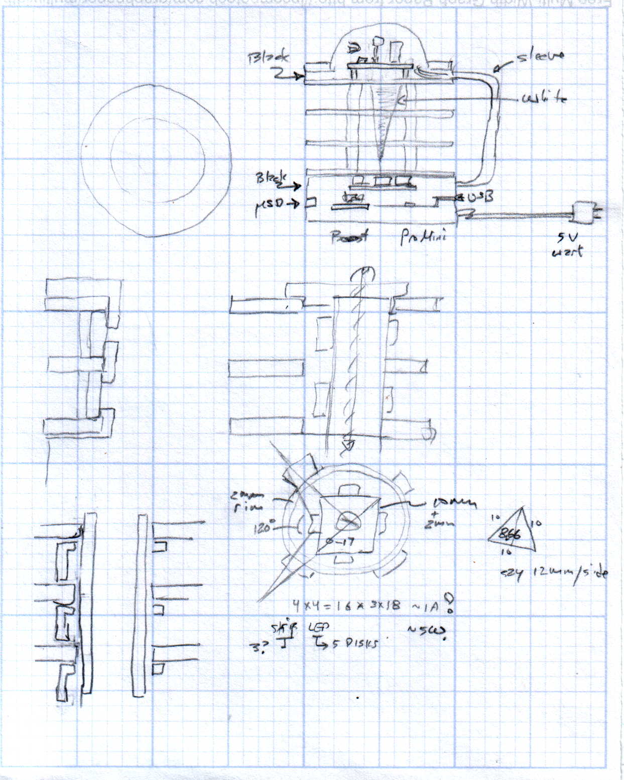
    The original doodles showing this might work, along with some ideas that wouldn’t:
    Hard Drive Mood Light - Doodles 1
    Hard Drive Mood Light – Doodles 1
    Hard Drive Mood Light - Doodles 2
    Hard Drive Mood Light – Doodles 2
    Hard Drive Mood Light - Doodles 3
    Hard Drive Mood Light – Doodles 3
  • Tiny Cylinder Test Object

    A discussion on the M2 forums prompted this test object:
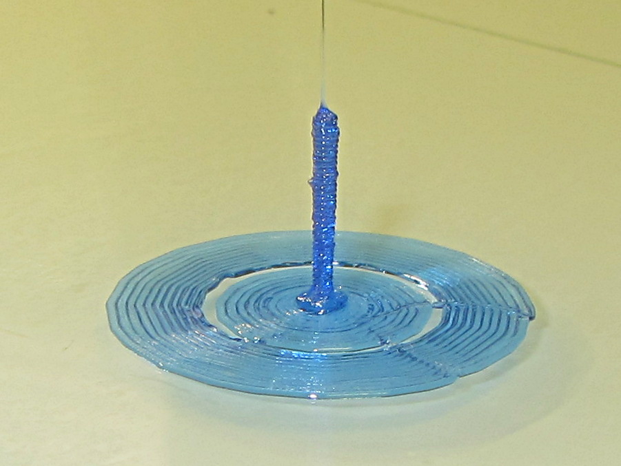
    Tiny Cylinder - 0.9x9.0 mm
    Tiny Cylinder – 0.9×9.0 mm

    Sliced with Slic3r for PETG at 1 mm/s, with fans in full effect. It sits amid a 5 mm brim, inside a skirt that uses 15 mm of filament, giving it a Washington Monument aspect.

    The challenge was to print a 0.7x9.0 cylinder, which doesn’t work well with a 0.35 mm nozzle. Instead, I went with 0.9 mm diameter. The result measures 1.1 mm over all the obvious bumps, so it’s surprisingly close. The “nail head” at the bottom most likely comes from the hot end depressurizing as it suddenly transitions from 15 mm/s in the brim to 1 mm/s for the cylinder.

    Fairly obviously, you can’t print something like that at full speed (50 mm/s was claimed for a Rep 2 and I don’t believe that for an instant). Indeed, it’s such a pathological model that Slic3r’s minimum layer time and small perimeter settings had no effect; I had to manually set the extrusion speed to 1 mm/s in order to make it work. Plus adding that brim, because I knew it wouldn’t stand by itself.

    Other than that, printing it was no big deal.

    A picture from that M2 forum discussion suggests you can go crazy with this stuff:
    20 mm, 40 mm, 60 mm and 120 mm
    20 mm, 40 mm, 60 mm and 120 mm

    The OpenSCAD source code for my version:

    cylinder(d=0.9,h=9,$fn=8);
    

    There, now, that wasn’t so hard, was it?

  • Stabbing Guides

    Many of my solid models have holes for alignment pins made from filament snippets that let me glue the pieces together with near-perfect registration:

    Alignment Hole and Pin
    Alignment Hole and Pin

    A reader who designs oil-field equipment for a living pointed out that, in his world, they’re called “stabbing guides”:

    Stabbing_Point_on_Leg_1
    Stabbing_Point_on_Leg_1

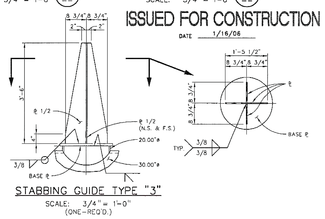
    He specifies steel plate and welding instructions:

    Stabbing_Guide_Type_3
    Stabbing_Guide_Type_3

    Stabbing guides for large modules may rise 25 feet above the deck plates…

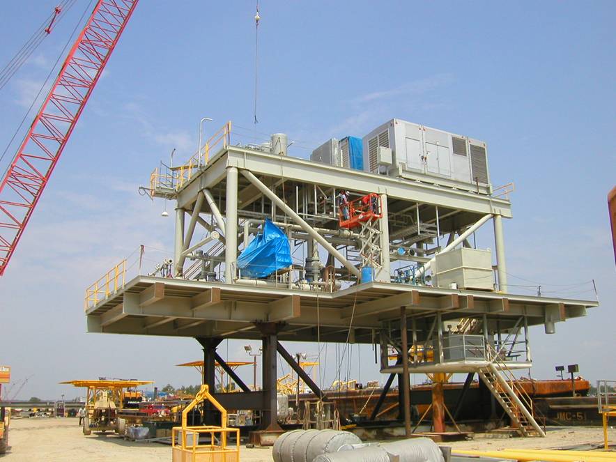
    After they install all the little bits on a “part” like this:

    Generator Module - during assembly
    Generator Module – during assembly

    It fits neatly atop the stabbing guides and gets welded to a somewhat larger structure:

    Generator Module - installed
    Generator Module – installed

    No sissy plastic for him!

    My puny pins don’t qualify as stabbing guides, but forgive me if I sneak the term in every now and then…

    Thanks, Tom!

  • Thinwall Hollow Box for Platform Alignment: Bottom Layer Images

    Sticking an extruded plastic thread to the platform of a 3D printer requires absolutely accurate alignment and spacing, maybe ±0.05 mm across the entire platform. I’ll leave the topic of automatic alignment measurement & compensation for another day; here’s how to measure the actual platform alignment.

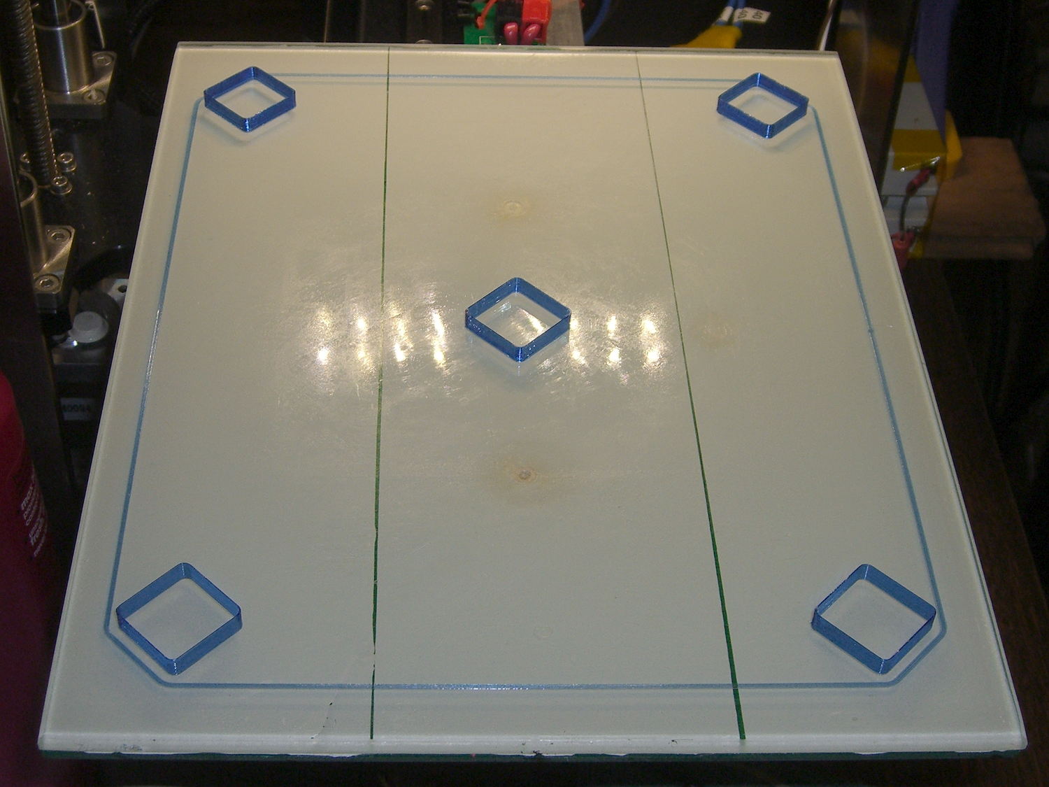
    Distribute five thinwall hollow boxes across the build platform:

    M2 V4 nozzle - thinwall boxes
    M2 V4 nozzle – thinwall boxes

    If the wall thickness (in the XY plane) doesn’t come out exactly right, fix that first by verifying the filament diameter setting, then adjusting the Extrusion Multiplier. If the extruder doesn’t produce the same wall thickness that the slicer calls for, you won’t get good results from anything else. In this case, they all have 0.40 mm thick walls, with 0.25 mm layers.

    The first layer of all five boxes should be identical:

    M2 V4 nozzle - thinwall box first layer
    M2 V4 nozzle – thinwall box first layer

    If the platform isn’t absolutely flat and properly aligned, those five first layers won’t be the same thickness. It’s surprisingly easy to spot differences under 0.05 mm, so pay attention to what’s happening.

    When they’re done, pop them off and measure their actual height. I measure across adjacent sides, leaving the corners / stray hairs / snot out of the measurement, and figure the eyeballometric average of the values, which usually differ by less than ±0.03 mm. Write the height on the side to eliminate future angst:

    Thinwall Box - platform height
    Thinwall Box – platform height

    The boxes should be 5.00 mm tall, so the leftmost box is short by -0.02 mm and the rightmost by -0.15 mm. The five boxes were 4.98, 4.95, 4.93, 4.92, and 4.85, with a mean of 4.93 mm. The variation across the 200×250 mm platform is 0.13 mm, which is pretty good.

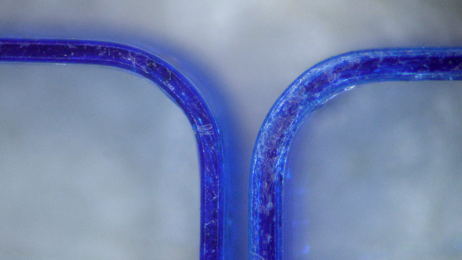
    Comparing the bottom layers of those boxes, the first layer of the 4.85 mm box is definitely squashed:

    Thinwall Hollow Boxes - first layer bottom view - 4.98 4.85 mm
    Thinwall Hollow Boxes – first layer bottom view – 4.98 4.85 mm

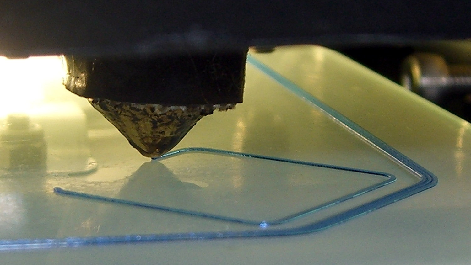
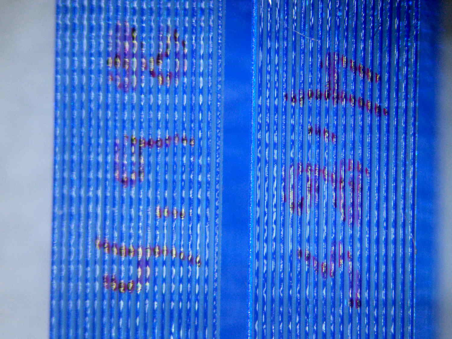
    Once you know what to look for, it’s also obvious from the side (4.98 on the left, 4.85 on the right, bottom layers facing each other):

    Thinwall boxes - 4.98 4.85 - bottom layers
    Thinwall boxes – 4.98 4.85 – bottom layers

    Keep in mind that’s a difference of 0.13 mm = 130 µm, just over the ±0.05 mm I usually bandy about. The nominal layers are 0.25 mm = 250 µm.

    A bit more magnification shows the nicely rounded first layer of the 4.98 mm box (rightmost thread of leftmost set):

    Thinwall Box - 4.98 mm
    Thinwall Box – 4.98 mm

    And the squashed first layer of the 4.85 mm box (likewise):

    Thinwall Box - 4.85 mm
    Thinwall Box – 4.85 mm

    Because the Z axis moves upward (on the M2, the platform moves downward) by exactly the layer thickness at the end of each layer, the first layer must absorb the entire difference between the desired thickness and the actual nozzle-to-platform distance. That squashed first layer is 0.10 mm thick, a bit less than half of the nominal 0.25 mm. The second layer of each box looks just like all the higher layers.

    Adjusting the first layer thickness by tweaking the initial Z-axis home position in the startup G-Code allows fine tuning without fussing with the mechanical settings. Having moved the Z-axis home switch to the middle of the X-axis gantry eliminates all those adjustments; tweaking the G-Code is the only way to go.

    You can set the Z-axis offset for a very slight squish, with the maximum nozzle-to-platform distance at 0.25 mm and the minimum set by the other end of the total misalignment, because the plastic won’t adhere to the platform when the nozzle-to-platform distance exceeds the nozzle diameter.

    Think of it this way: the plastic emerges from a 0.35 mm nozzle as a (slightly larger than) 0.35 mm cylinder that must squash to become a 0.25 mm high x 0.40 mm wide thread. Given the measurements above, setting the Z-axis home position to make the average box height equal to 5.00 mm would make the tallest box come out at 5.07 mm, which requires a 0.32 mm actual first layer that probably wouldn’t stick well at all.

    When your printer can consistently produce five thinwall boxes with the proper wall thickness and height, then you can move on to more complex objects.

    Selah.

  • Epoxy-filled 3D Printed Characters

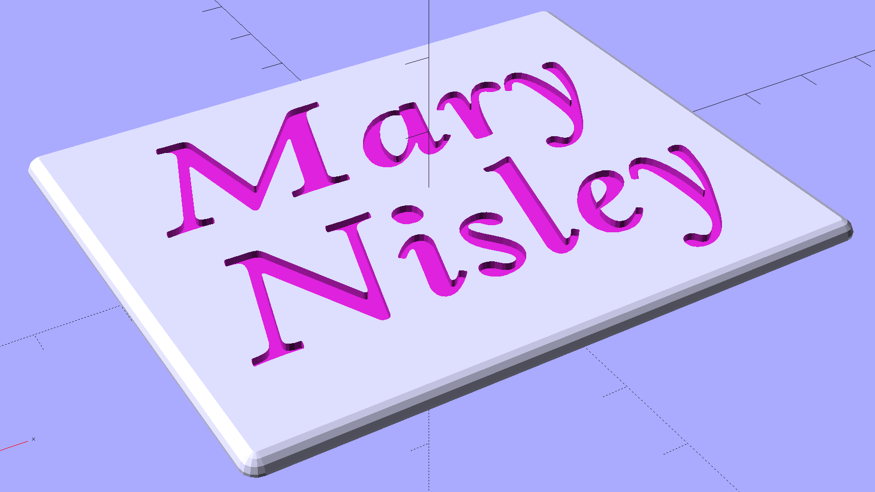
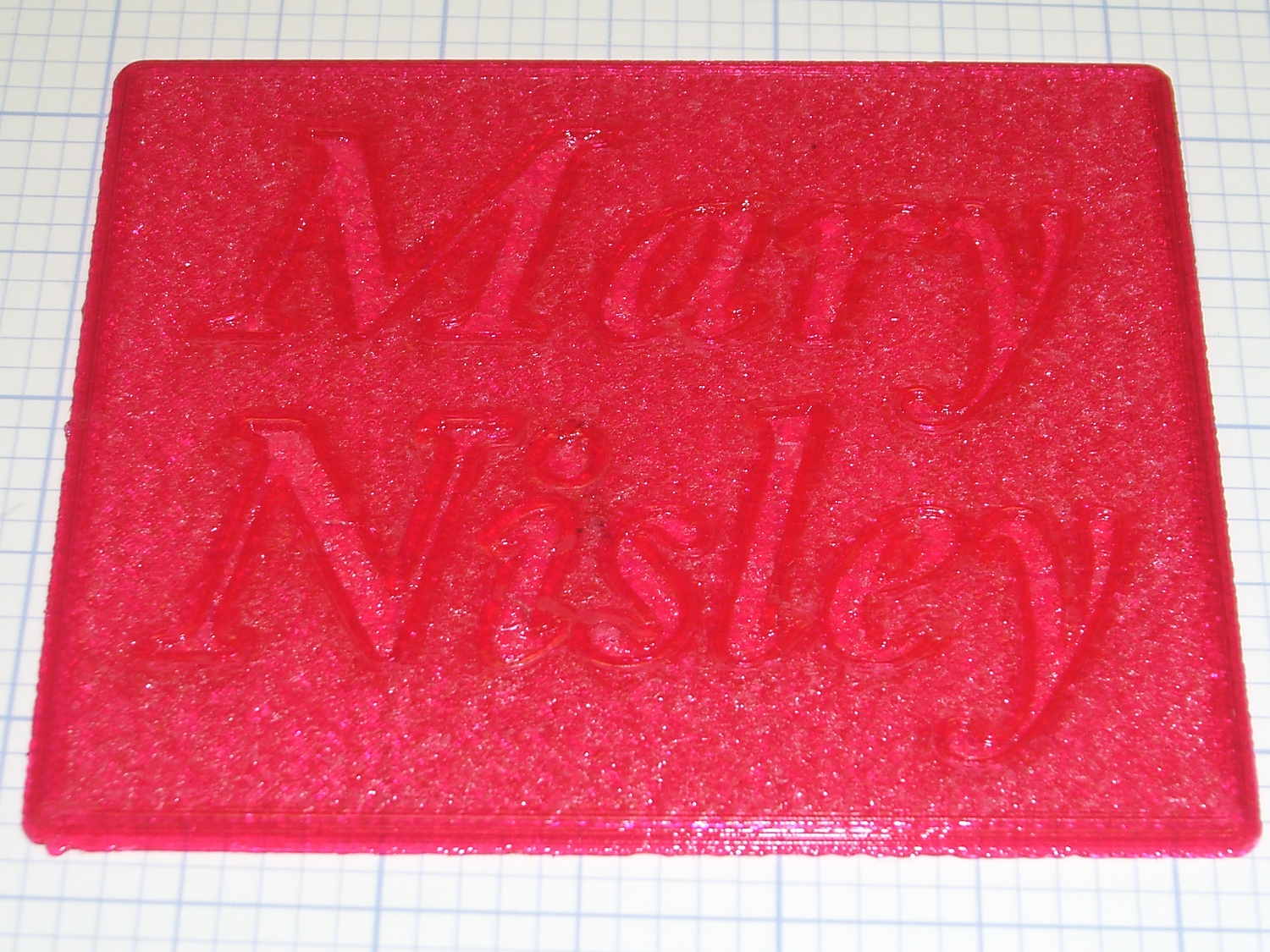
    Although Mary’s name in the base of the Clover Mini Iron holder was readable in person, I wondered what filling the characters with epoxy would do. A bit of tinkering produced a name plate:

    Text Block - solid model
    Text Block – solid model

    Which is more readable in person, but magenta PETG renders it basically unreadable here:

    Text Block - unfilled
    Text Block – unfilled

    The intent of this was not to produce a lovely name block, but to see what various epoxy fills and techniques produced. Think of this as the one you must build to throw away…

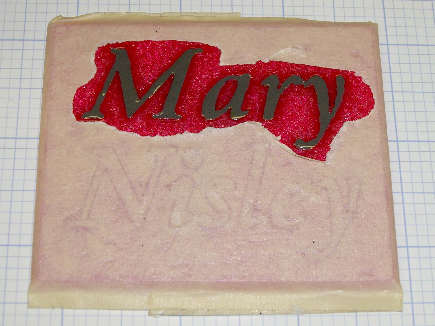
    I tediously filled the first line with straight JB Weld epoxy, deliberately ruining the least functional of my 1 ml syringes to ease a strand of epoxy into each letter, then poking the goo into place with a pointed rod:

    Text Block - plain epoxy fill
    Text Block – plain epoxy fill

    That was way tedious.

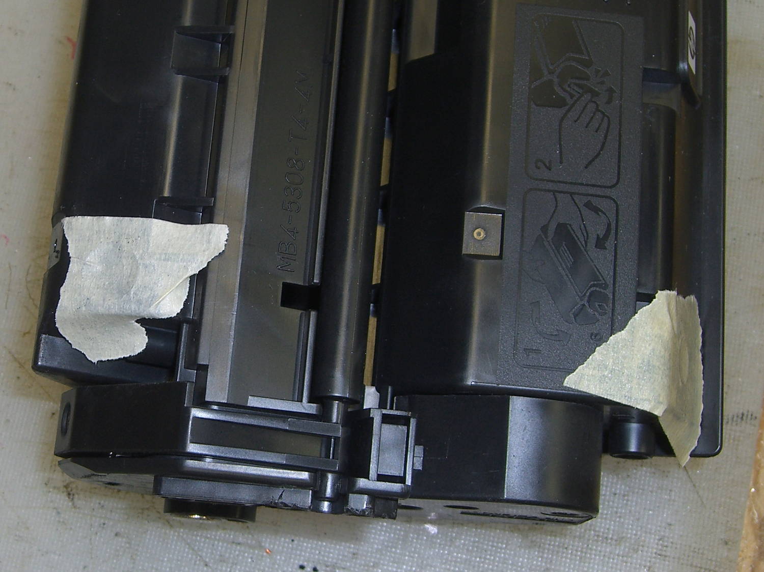
    Having recently replaced the cartridge in our trusty HP Laserjet 1200, I had no qualms about step-drilling the “empty” cartridge to get the toner. For future reference, here’s where you drill into a 7115X cartridge:

    HP 7115X Toner Cartridge - holes in waste and supply compartments
    HP 7115X Toner Cartridge – holes in waste and supply compartments

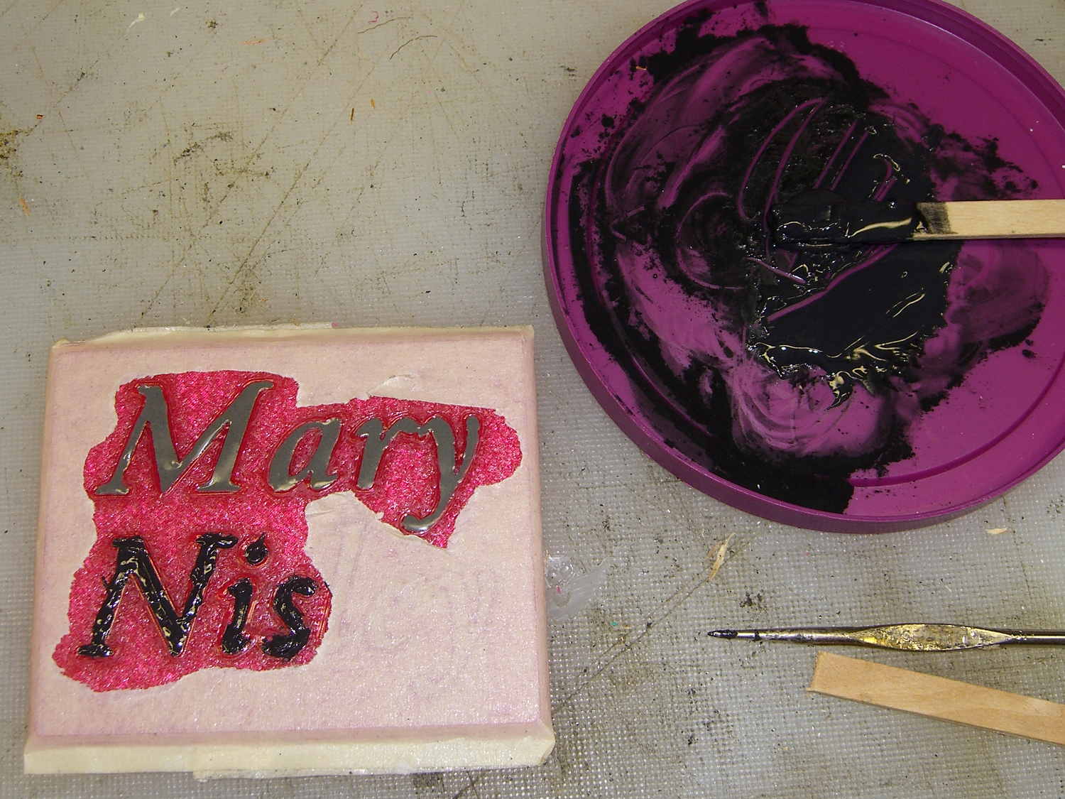
    I probably used too much toner, but one heaping pile on that wooden stick didn’t seem like a lot at the time:

    Text Block - toner black epoxy
    Text Block – toner black epoxy

    This turned the epoxy rather thick and pasty; it didn’t ease into the letters very well at all. After the usual day, it cured into a slightly rubbery solid, quite unlike the usual rock-solid epoxy blob.

    Some rummaging in the Basement Laboratory Warehouse Wing turned up two containers of aluminum powder from an Etch-a-Sketch; I mixed some into another batch of epoxy, to very little effect. With both blends, I just squished the epoxy into the letters and didn’t worry too much about slobbering any over the surface of the block.

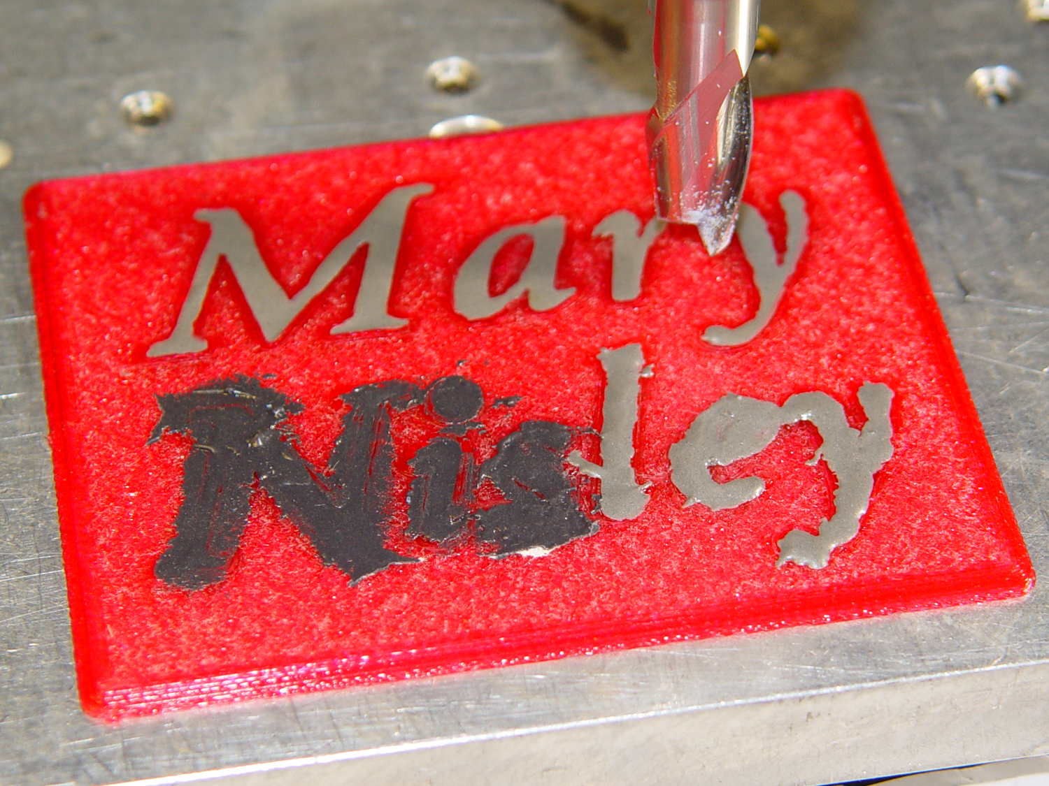
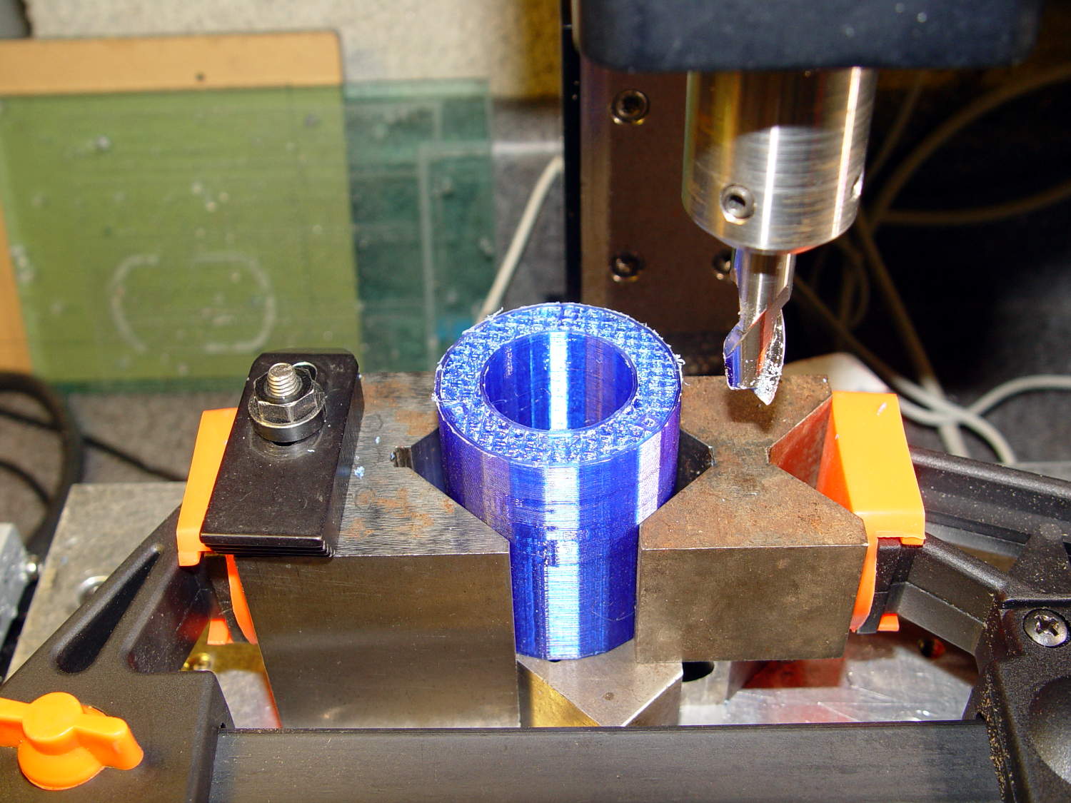
    To even off the top surface, I affixed the block to the Sherline’s tooling plate with tapeless sticky (basically double-sided tape without the tape):

    Text Block - milling setup
    Text Block – milling setup

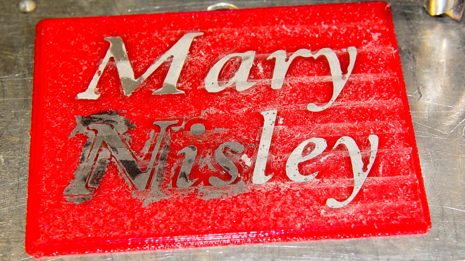
    Manually traversing the surface (3 k rpm, 24 inch/min) and stepping downward about 0.1 mm per pass gradually crisped up the letters. I expected the excess epoxy to vanish after going 0.1 mm or so into the top layer, but it actually required removing the entire 0.25 mm Hilbert-curve-filled surface layer to get rid of the epoxy that soaked into / through the tiny gaps. This is 0.4 mm down from the first pass, maybe 0.1 mm into the plastic:

    Text Block - milled 0.4 mm
    Text Block – milled 0.4 mm

    With the top layer gone, it looked rather gnarly, so I applied a sanding block that didn’t do much at all: smoother, still gnarly. Spreading maybe 0.3 ml of IPS 4 solvent adhesive over the sanded surface smoothed it a bit:

    Text Block - sanded and leveled with IPS 4
    Text Block – sanded and leveled with IPS 4

    Perhaps a topcoat of clear epoxy, along the lines of XTC-3D, would produce better results.

    The small black dots in the top line are holes from bubbles in the epoxy. The missing section of the M started out as a bubble (just visible at 0.4 mm) and gradually enlarged as pieces tore out of the recess. There’s another bubble breaking the right stroke of the “y”.

    The small dots in the “ley” are plastic spheres that carried the aluminum powder in the Etch-a-Sketch; they’re cross-sectioned and perfectly flat. The epoxy color is marginally lighter than the top line, but not enough to notice.

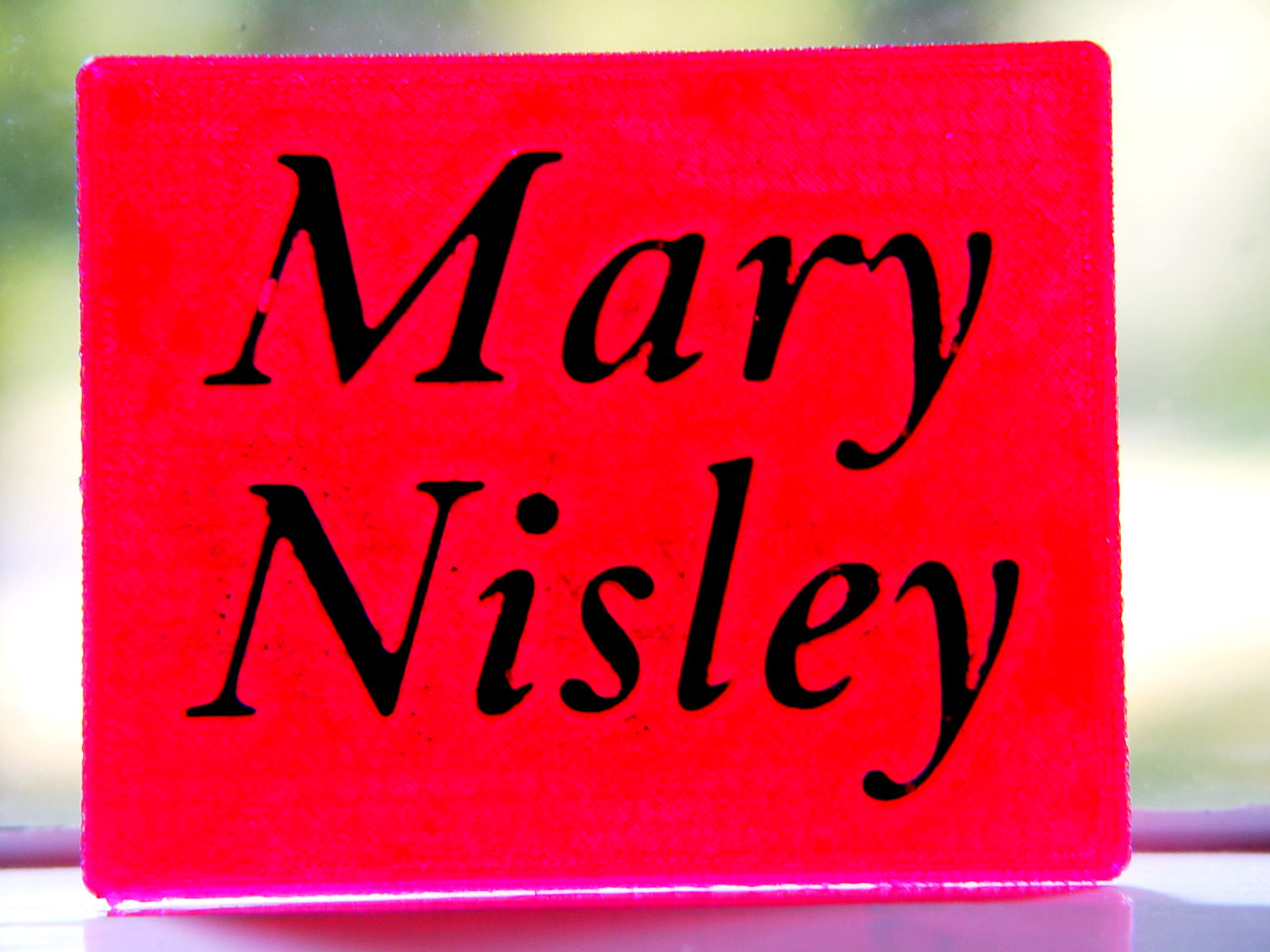
    Backlit on a window, nearly all of the ugly fades away:

    Text Block - backlit
    Text Block – backlit

    It’s definitely not presentation quality, that’s for sure, and I won’t attempt to fill the Mini Iron holder…

    The OpenSCAD source code, which can also produce the soldering iron holder:

    // Clover MCI-900 Mini Iron holder
    // Ed Nisley KE4ZNU - August 2015
    
    Layout = "Text";					// Iron Holder Show Text
    
    //- Extrusion parameters - must match reality!
    
    ThreadThick = 0.25;
    ThreadWidth = 0.40;
    
    function IntegerMultiple(Size,Unit) = Unit * ceil(Size / Unit);
    
    Protrusion = 0.1;
    
    HoleWindage = 0.2;
    
    inch = 25.4;
    
    Tap10_32 = 0.159 * inch;
    Clear10_32 = 0.190 * inch;
    Head10_32 = 0.373 * inch;
    Head10_32Thick = 0.110 * inch;
    Nut10_32Dia = 0.433 * inch;
    Nut10_32Thick = 0.130 * inch;
    Washer10_32OD = 0.381 * inch;
    Washer10_32ID = 0.204 * inch;
    
    //------
    // Dimensions
    
    CornerRadius = 4.0;
    
    CenterHeight = 25;							// center at cord inlet on body
    
    BodyLength = 110;							// cord inlet to body curve at front flange
    
    Incline = 10;								// central angle slope
    
    FrontOD = 29;
    FrontBlock = [20,1.5*FrontOD + 2*CornerRadius,FrontOD/2 + CenterHeight + BodyLength*sin(Incline)];
    
    CordOD = 10;
    CordLen = 10;
    
    RearOD = 22;
    RearBlock = [15 + CordLen,1.5*RearOD + 2*CornerRadius,RearOD/2 + CenterHeight];
    
    PlateWidth = 2*FrontBlock[1];
    
    TextDepth = 4*ThreadThick;
    
    ScrewOC = BodyLength - FrontBlock[0]/2;
    ScrewDepth = CenterHeight - FrontOD/2 - 5;
    
    echo(str("Screw OC: ",ScrewOC));
    
    BuildSize = [200,250,200];					// largest possible thing
    
    module PolyCyl(Dia,Height,ForceSides=0) {			// based on nophead's polyholes
    
      Sides = (ForceSides != 0) ? ForceSides : (ceil(Dia) + 2);
    
      FixDia = Dia / cos(180/Sides);
    
      cylinder(r=(FixDia + HoleWindage)/2,
               h=Height,
    	   $fn=Sides);
    }
    
    // Trim bottom from child object
    
    module TrimBottom(BlockSize=BuildSize,Slice=CornerRadius) {
    	
    	intersection() {
    		translate([0,0,BlockSize[2]/2])
    			cube(BlockSize,center=true);
    		translate([0,0,-Slice])
    			children();
    	}
    }
    
    // Build a rounded block-like thing
    
    module RoundBlock(Size=[20,25,30],Radius=CornerRadius,Center=false) {
    	
    	HS = Size/2 - [Radius,Radius,Radius];
    	translate([0,0,Center ? 0 : (HS[2] + Radius)])
    	hull() {
    		for (i=[-1,1], j=[-1,1], k=[-1,1]) {
    			translate([i*HS[0],j*HS[1],k*HS[2]])
    				sphere(r=Radius,$fn=4*4);
    		}
    	}
    }
    
    // Create a channel to hold something
    // This will eventually be subtracted from a block
    // The offsets are specialized for this application...
    
    module Channel(Dia,Length) {
    	
    	rotate([0,90,0])
    		linear_extrude(height=Length)
    			rotate(90)
    				hull() {
    					for (i=[-1,1])
    						translate([i*Dia,2*Dia])
    							circle(d=Dia/8);
    					circle(d=Dia,$fn=8*4);
    				}
    }
    
    // Iron-shaped series of channels to be removed from blocks
    
    module IronCutout() {
    
    	union() {
    		translate([-2*CordLen,0,0])
    			Channel(CordOD,2*CordLen + Protrusion);
    		Channel(RearOD,RearBlock[0] + Protrusion);
    		translate([BodyLength - FrontBlock[0]/2 - FrontBlock[0],0,0])
    			Channel(FrontOD,2*FrontBlock[0]);
    
    	}
    	
    }
    
    module TextBlock() {
    	translate([2,10,0])
    		linear_extrude(height=TextDepth + Protrusion,convexity=2)		// rendering glitches for convexity > 1
    //			text("Mary",font="Ubuntu:style=Bold Italic",halign="center",valign="center");
    			text("Mary",font="Junicode:style=Bold Italic",halign="center",valign="center",size=20,spacing=1.05);
    			
    	translate([2,-15,0])
    		linear_extrude(height=TextDepth + Protrusion,convexity=2)
    			text("Nisley",font="Junicode:style=Bold Italic",halign="center",valign="center",size=20,spacing=1.05);
    	
    }
    
    //- Build it
    
    if (Layout == "Iron")
    	IronCutout();
    
    if (Layout == "Holder" || Layout == "Show")
    	difference() {
    		union() {
    			translate([(BodyLength + CordLen)/2 - CordLen,0,0])
    				TrimBottom()
    					RoundBlock(Size=[(CordLen + BodyLength),PlateWidth,CornerRadius]);
    
    			translate([(RearBlock[0]/2 - CordLen),0,0])
    				TrimBottom()
    					RoundBlock(Size=RearBlock);
    
    			translate([BodyLength - FrontBlock[0]/2,0,0]) {
    				TrimBottom()
    					RoundBlock(Size=FrontBlock);
    			}
    		}
    		
    		translate([0,0,CenterHeight])
    			rotate([0,-Incline,0])
    				if (Layout == "Show")
    #					IronCutout();
    				else
    					IronCutout();
    		
    		translate([0,0,-Protrusion])
    			PolyCyl(Tap10_32,ScrewDepth + Protrusion,6);
    			
    		translate([ScrewOC,0,-Protrusion])
    			PolyCyl(Tap10_32,ScrewDepth + Protrusion,6);
    
    		translate([(RearBlock[0] - CordLen) + BodyLength/2 - FrontBlock[0],0,CornerRadius - TextDepth])
    			TextBlock();
    		
    	}
    	
    if (Layout == "Text")
    	difference() {
    		translate([0,0,0])
    			TrimBottom(Slice=8*ThreadThick)
    				RoundBlock(Size=[80,65,8*ThreadThick],Radius=8*ThreadThick);
    #		translate([-2,2,8*ThreadThick - TextDepth])
    			TextBlock();
    
    	}
    
  • Stereo Zoom Microscope: USB Camera Mount

    My stereo zoom microscope neatly filled the entrance pupil of the late, lamented Casio EX-Z850, so that a simple adapter holding it on the eyepiece produced credible images:

    Thinwall open boxes - side detail - 4.98 4.85 measured
    Thinwall open boxes – side detail – 4.98 4.85 measured

    Alas, the shutter failed after that image, leaving me with pictures untaken and naught to take them with.

    The least-awful alternative seems to be gimmicking up an adapter for a small USB camera from the usual eBay source:

    Fashion USB video - case vs camera
    Fashion USB video – case vs camera

    The camera’s 640×480 VGA resolution is marginally Good Enough for the purpose, as I can zoom the microscope to completely fill all those pixels. The optics aren’t up to the standard set by the microscope, but we can cope with that for a while.

    A bit of doodling & OpenSCAD tinkering produced a suitable adapter:

    USB Camera Microscope Mount - solid model
    USB Camera Microscope Mount – solid model

    To which Slic3r applied the usual finishing touches:

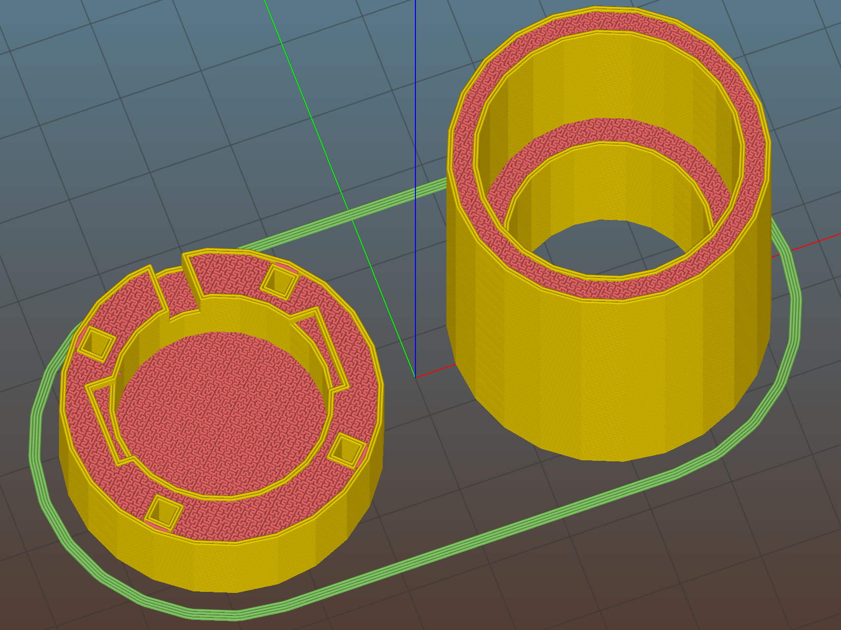
    USB Camera Microscope Mount - Slic3r preview
    USB Camera Microscope Mount – Slic3r preview

    A bit of silicone tape holds the sloppy focusing thread in place:

    USB Camera Microscope Mount - cap with camera
    USB Camera Microscope Mount – cap with camera

    Those are 2-56 screws that will hold the cap onto the tube. I drilled out the clearance holes in the cap and tapped the holes in the eyepiece adapter by hand, grabbing the bits with a pin vise.

    Focus the lens at infinity, which in this case meant an old DDJ cover poster on the far wall of the Basement Laboratory, and then it’ll be just as happy with the image coming out of the eyepiece as a human eyeball would be.

    I put a few snippets of black electrical tape atop the PCB locating tabs before screwing the tube in place. The tube ID is 1 mm smaller than the PCB OD, in order to hold the PCB perpendicular to the optical axis and clamp it firmly in place. Come to find out that the optical axis of the lens isn’t perfectly perpendicular to the PCB, but it’s close enough for my simple needs.

    And then it fits just like you’d expect:

    USB Camera Microscope Mount - on eyepiece
    USB Camera Microscope Mount – on eyepiece

    Actually, that’s the second version. The distance from the camera lens (equivalently: the PCB below the optical block, which I used as the datum plane) to the eyepiece is a critical dimension that determines whether the image fills the entrance pupil. I guesstimated the first version by hand-holding the camera and measuring with a caliper, tried it out, then iteratively whacked 2 mm off the tube until the image lit up properly:

    USB Camera Microscope Mount - adjusting tube length
    USB Camera Microscope Mount – adjusting tube length

    Minus 4 mm made it slightly too short, but then I could measure the correct position, tweak that dimension in the code, and get another adapter, just like the first one (plus a few other minor changes), except that it worked:

    USB Camera Microscope Mount - first light
    USB Camera Microscope Mount – first light

    That’s a screen capture from VLC, which plays from /dev/video0 perfectly. Some manual exposure & color balance adjustment may be in order, but it’s pretty good for First Light.

    It turns out that removing the eyepiece and holding the bare sensor over the opening also works fine. The real image from the objective fills much more area than the camera’s tiny sensor: the video image covers about one digit in that picture, but gimmicking up a bare-sensor adapter might be useful.

    The OpenSCAD source code:

    // USB Camera mount for Microscope Eyepiece
    // Ed Nisley KE4ZNU - August 2015
    
    Layout = "Build";                    // Show Build Mount Cap
    
    //-------
    //- Extrusion parameters must match reality!
    //  Print with 2 shells
    
    ThreadThick = 0.25;
    ThreadWidth = 0.40;
    
    HoleWindage = 0.2;
    
    Protrusion = 0.1;           // make holes end cleanly
    
    function IntegerMultiple(Size,Unit) = Unit * ceil(Size / Unit);
    
    inch = 25.4;
    
    Tap2_56 = 0.070 * inch;
    Clear2_56 = 0.082 * inch;
    Head2_56 = 0.156 * inch;
    Head2_56Thick = 0.055 * inch;
    Nut2_56Dia = 0.204 * inch;
    Nut2_56Thick = 0.065 * inch;
    Washer2_56OD = 0.200 * inch;
    Washer2_56ID = 0.095 * inch;
    
    BuildGap = 5.0;
    
    //-------
    // Dimensions
    
    //-- Camera
    
    PCBThick = 1.1;
    PCBDia = 24.5;
    PCBClampDia = 23.0;
    
    KeySize = [IntegerMultiple(27.6,ThreadWidth),IntegerMultiple(9.5,ThreadWidth),IntegerMultiple(PCBThick,ThreadThick)];
    KeyOffset = [0.0,1.5,0];
    
    CameraOffset = 22.3;                    // distance from eyepiece to camera PCB
    
    WallThick = 4.0;
    
    EyePieceOD = 30.0;
    EyePieceLen = 30.0;
    
    BodyOD = EyePieceOD + 2*WallThick;
    BodyLen = CameraOffset + EyePieceLen - 5.0;
    
    echo(str("Body length: ",BodyLen));
    
    CapSocket = 10;
    CapLen = CapSocket + WallThick;
    CableOD = 3.7;
    
    echo(str("Cap length: ",CapLen));
    
    
    echo(str("Total length: ",BodyLen + CapLen));
    
    NumScrews = 4;
    ScrewAngle = 45;
    
    NumSides = 6*4;
    
    //-------
    
    module PolyCyl(Dia,Height,ForceSides=0) {           // based on nophead's polyholes
        Sides = (ForceSides != 0) ? ForceSides : (ceil(Dia) + 2);
        FixDia = Dia / cos(180/Sides);
        cylinder(r=(FixDia + HoleWindage)/2,
                 h=Height,
                 $fn=Sides);
    }
    
    
    //-------
    // Components
    
    module LensMount() {
        
        difference() {
            cylinder(d=BodyOD,h=BodyLen,$fn=NumSides);
            translate([0,0,CameraOffset])
                PolyCyl(EyePieceOD,EyePieceLen,NumSides);
            translate([0,0,-Protrusion])
                PolyCyl(PCBClampDia,(BodyLen + 2*Protrusion),NumSides);
            for (i=[0:NumScrews-1])
                rotate(ScrewAngle + i*360/NumScrews)
                    translate([(BodyOD/2 - 1.5*Head2_56/2),0,-Protrusion])
                        rotate(180/4)
                            PolyCyl(Tap2_56,10.0,4);
        }
    }
    
    module CamCap() {
        difference() {
            cylinder(d=BodyOD,h=CapLen,$fn=NumSides);
            translate([0,0,WallThick])
                PolyCyl(PCBDia,CapLen,NumSides);
            translate(KeyOffset + [0,0,(CapLen - KeySize[2]/2 + Protrusion/2)])
                cube((KeySize + [0,0,Protrusion]),center=true);
            if (false)
                translate([0,0,-Protrusion])
                    PolyCyl(CableOD,CapLen,8);
            else
                translate([0,BodyOD/2,(CapLen - CableOD/2 + Protrusion/2)])
                    rotate([90,0,0])
                        cube([CableOD,(CableOD + Protrusion),BodyOD],center=true);
            for (i=[0:NumScrews-1])
                rotate(ScrewAngle + i*360/NumScrews)
                    translate([(BodyOD/2 - 1.5*Head2_56/2),0,-Protrusion])
                        rotate(180/4)
                            PolyCyl(Clear2_56,(CapLen + 2*Protrusion),4);
            
        }
    }
    
    //-------
    // Build it!
    
    if (Layout == "Mount")
        LensMount();
    
    if (Layout == "Cap")
        CamCap();
    
    if (Layout == "Show") {
        CamCap();
        translate([0,0,CapLen + 5])
            LensMount();
    }
    if (Layout == "Build") {
        translate([-(BodyOD/2 + BuildGap),0,0])
            CamCap();
            translate([(BodyOD/2 + BuildGap),0,0])
            LensMount();
    }
    
  • DC Motor Mounting Plate

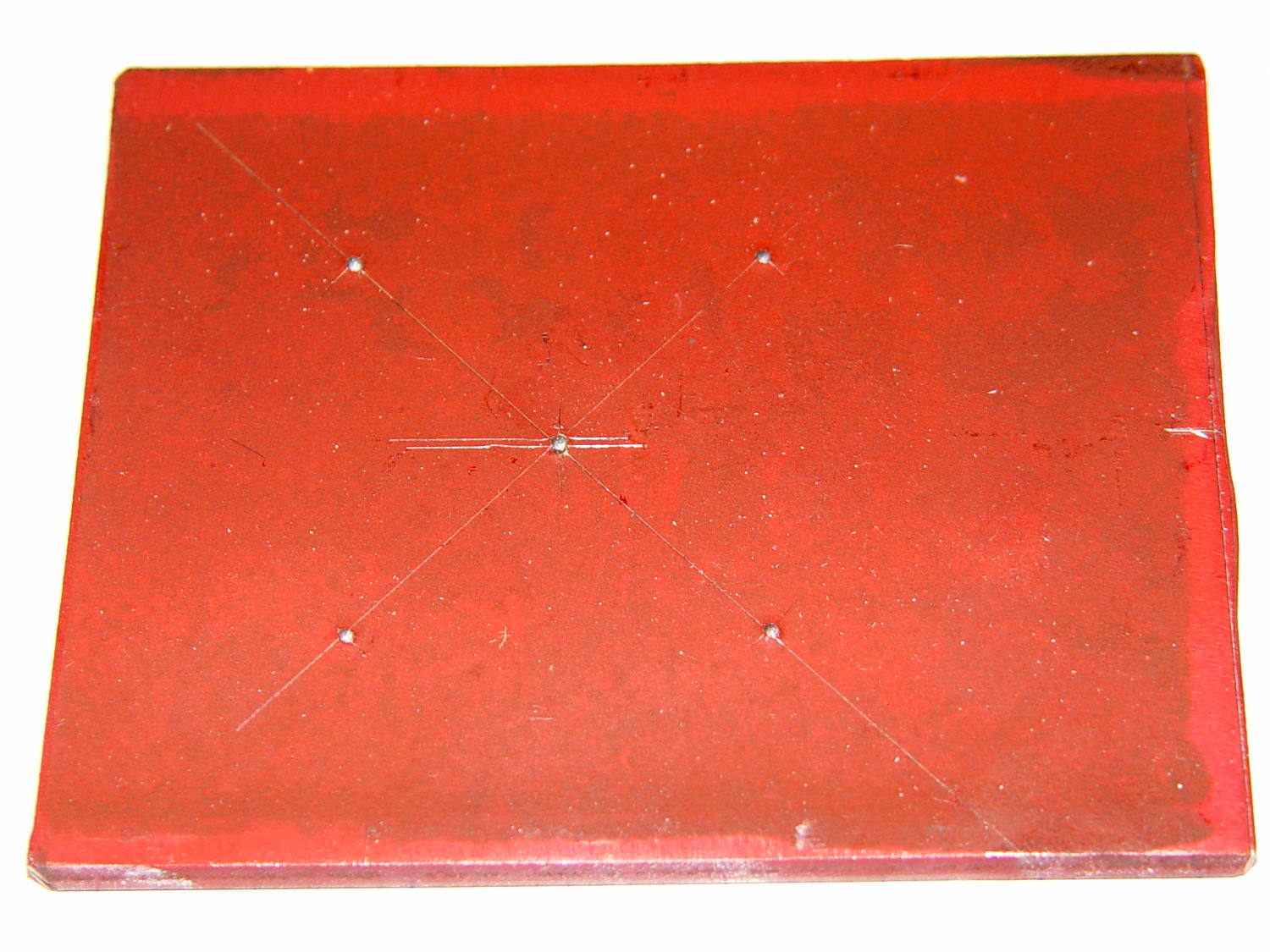
    The Squidwrench Power Wheels Racer needed a mounting bracket for its DC motor, so Matt handed me a precut steel slab and some drawings. I did a manual layout to get a feel for the sizes:

    Motor Mount - dye layout
    Motor Mount – dye layout

    Yes, it’s slightly rhomboid & irregular on the sides; it’ll be welded to a U-channel. The front edge is the straightest and I scribed a perpendicular datum line over on the right, from which to measure the motor center point.

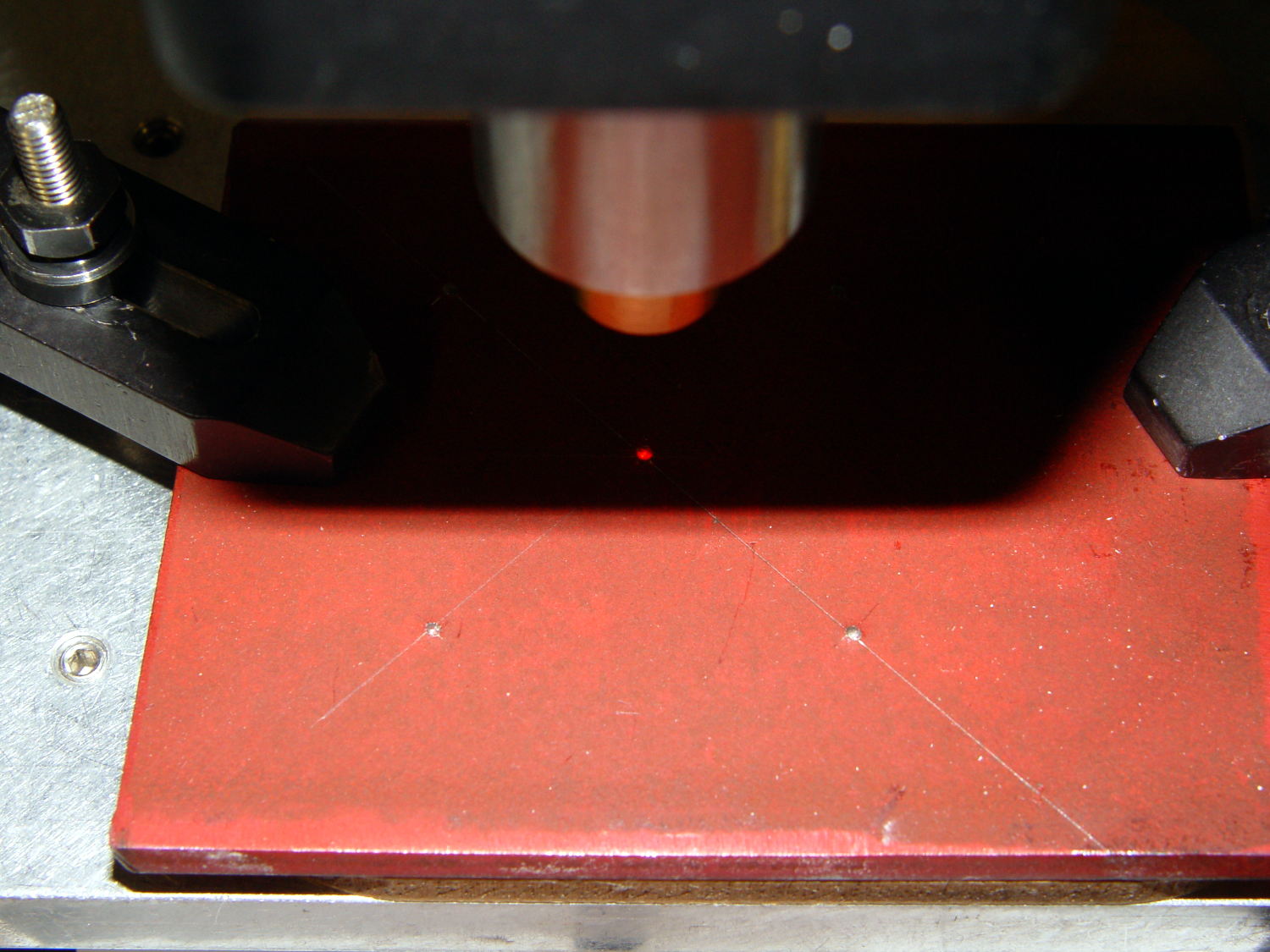
    But then, realizing I’d have to mill the central hole anyway, I did what I should have done from the beginning and lined it up on the Sherline:

    Motor Mount - Sherline laser centering
    Motor Mount – Sherline laser centering

    With the part zeroed at the center, everything has polar coordinates. The bolt holes are #10 on a 50 mm BCD, which is G0 @25^[45+90*i]. Rather than writing & debugging a program, I did it all by feeding manual instructions into the interpreter; the i gets typed as 0, 1, 2, and 3 by clicking on a previous command, backspacing, and retyping, which is both faster and easier than it sounds. The holes are drill cycles: G81 Z-7 R1 F30

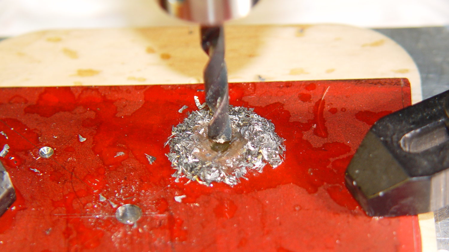
    This being steel on a Sherline, the rule of thumb that says you can drill at 100x the drill diameter (in inch/min or mm/min, as appropriate) at 3000 RPM gets derated by at least factor of 10. I settled on 30 mm/min for a #10 drill (0.194 inch = 4.9 mm → 500 mm/min = hogwash) after trying the first hole at 50 mm/min:

    Motor Mount - bolt holes
    Motor Mount – bolt holes

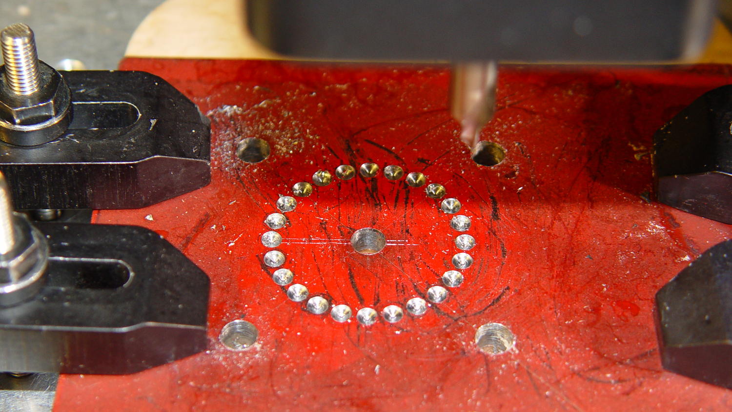
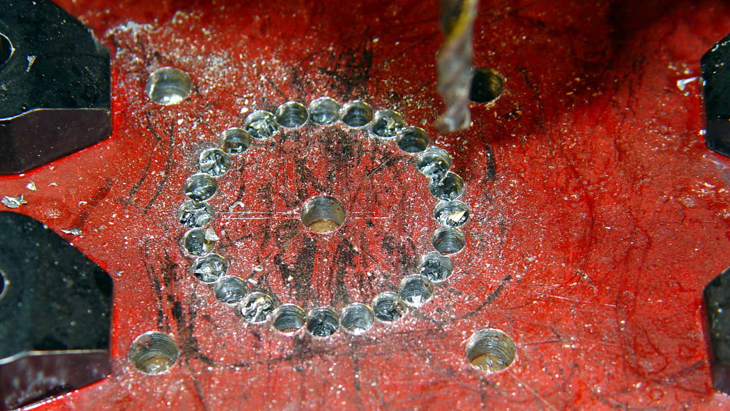
    The least horrible way to cut out the hole for the motor mounting boss involved chain drilling to excavate the most steel with the least effort. These center drill points are at G0 @14 ^[15*i] with i in [0..23]:

    Motor Mount - chain center drilling
    Motor Mount – chain center drilling

    I drilled every even hole #27, then every odd hole #28, both at 50 mm/min, to get a thin web:

    Motor Mount - chain drilled
    Motor Mount – chain drilled

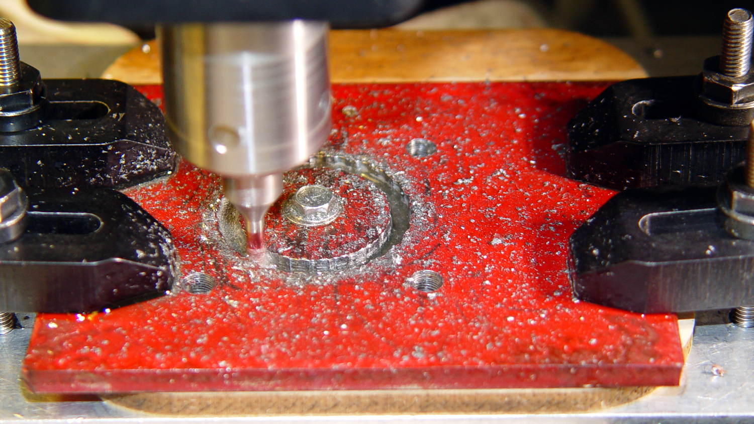
    Then helix-mill downward with a 1/8 inch end mill at 1 mm per pass:

    Motor Mount - helix milling
    Motor Mount – helix milling

    That started at 14 mm from the origin to match the hole circle: G3 I-14 F100 Z-1

    Then I switched to a 3/8 inch = 9.5 mm end mill to bring the hole up to size, ending with G3 I-12.75 F300

    Motor Mount - center hole milled
    Motor Mount – center hole milled

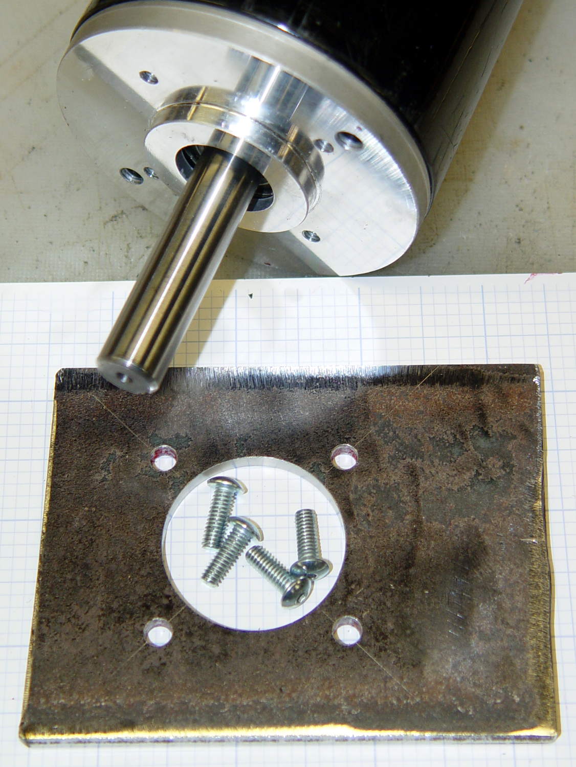
    A trial fit showed the hole was slightly off-round, probably due to a few mils of backlash in both axes, and slightly too small, because that’s how I wanted it. Flipped back-to-front, reclamped, recentered, ran the cutter around at 12.75 mm to clear the ovalness, then crept out to 12.8 mm, and it was all good:

    Motor Mount - test fit
    Motor Mount – test fit

    That’s an easy fit with maybe 0.1 mm = 4 mil radial play around the boss. Better than that, I cannot do.

    Lacquer thinner stripped the layout dye and it’s ready for welding:

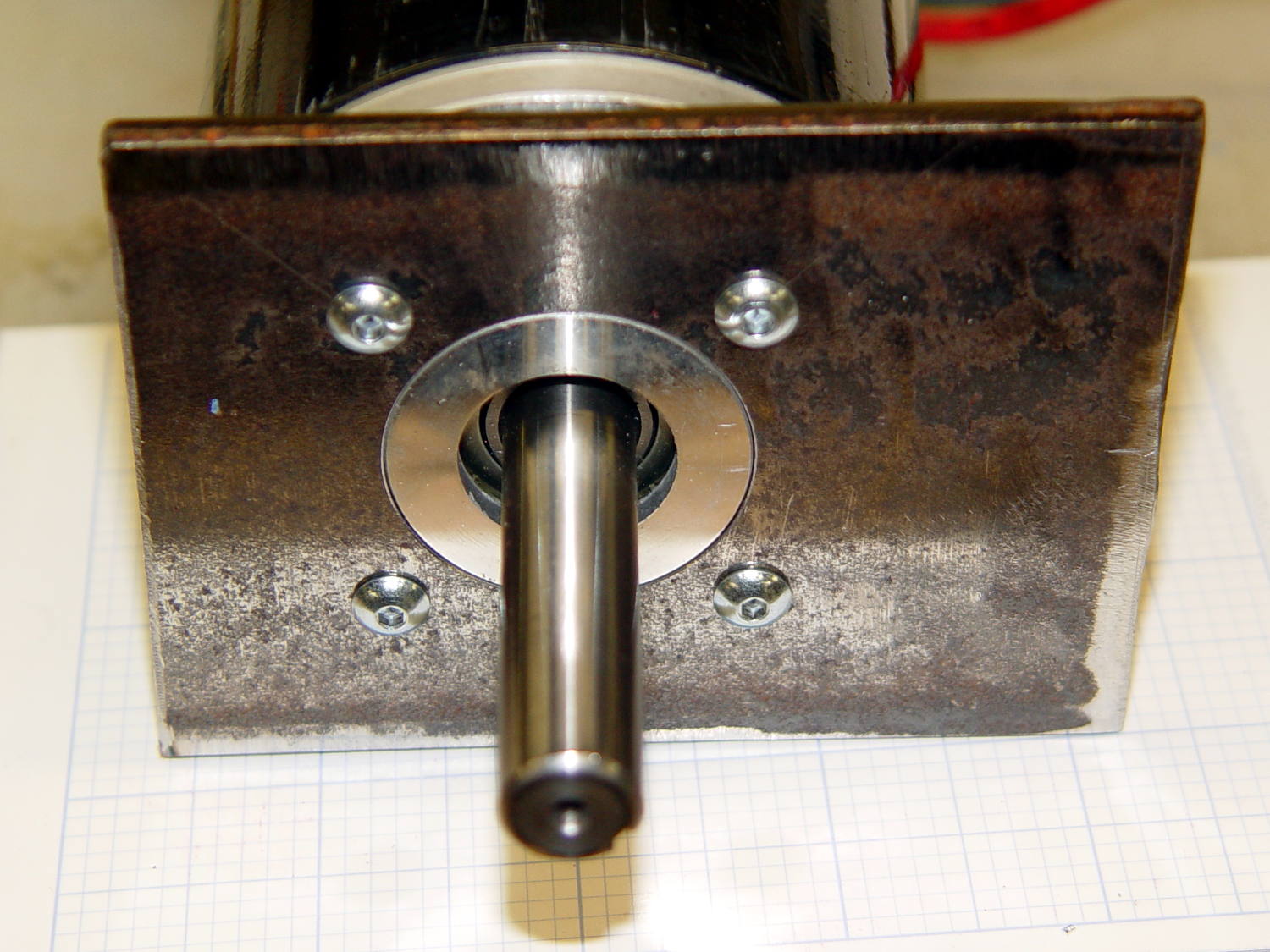
    Motor Mount - with motor
    Motor Mount – with motor

    Reminders for next time…

    The drill feed on a rigid machine with plenty of spindle power is 100 x (drill dia) @ 3000 RPM. On the Sherline, in steel, 10 x dia is optimistic. Aluminum feeds run higher, but don’t get stupid.

    Re-centering to the accuracy required for this job is a matter of noting the coordinates where the cutter kisses the perimeter across a diameter along each axis, adding the coordinates, dividing by two, moving to that position, and zeroing the origin. Do that in X, Y, X, and Y and it’s good enough. You could automate that with a touch probe, of course. Hand-turning the spindle with the cutter in place to feel it kiss the workpiece is fine, but use the same cutting edge on both sides of the diameter.

    Figure the chain drill diameter thusly:

    • Pick a reasonable drill diameter; #10 is about as large as you want on a Sherline
    • Drill circle dia = final milled hole diameter – drill dia – 2 mm, round down to lower integer
    • # holes = π x DCD / drill dia, rounded down to lower integer
    • Hole angle = 360 / # holes
    • Hole radius = DCD / 2

    Wisely is it written that a man with a CNC milling machine has many friends.