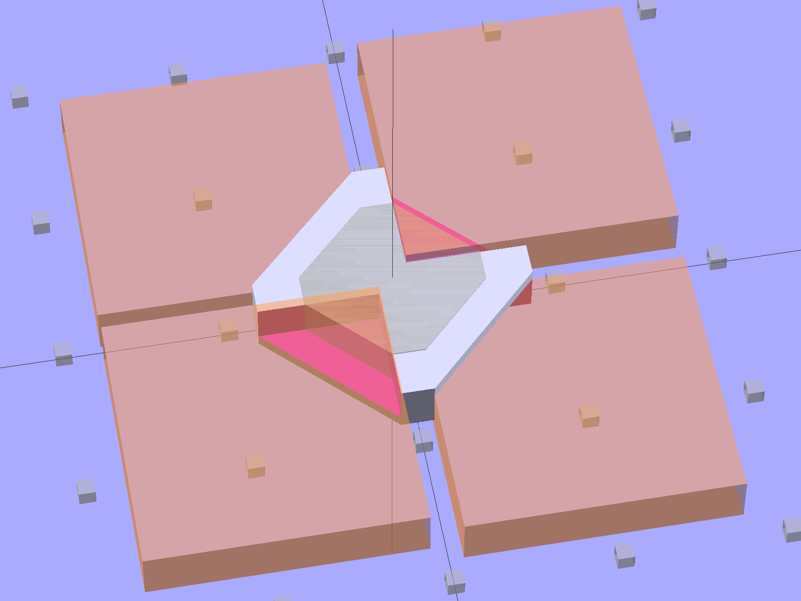
This is a subtractive version of Zomboe’s Chainmail, built by removing chunks from a solid rectangle the size of one link:
Until what’s left is, indeed, a single link:
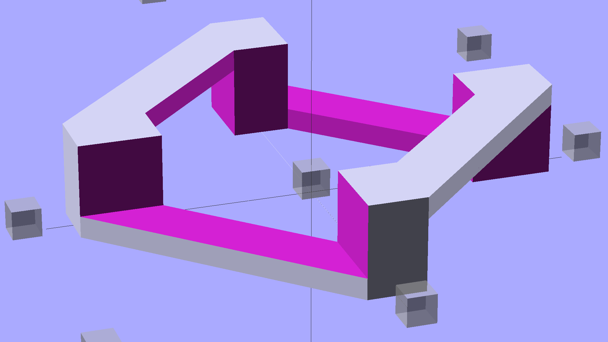
The pillars in the original model weren’t nearly large enough; Slic3r omitted them from the G-Code. They’re now as wide as the bars and √2 times that width long, which means they actually get a bit of fill.
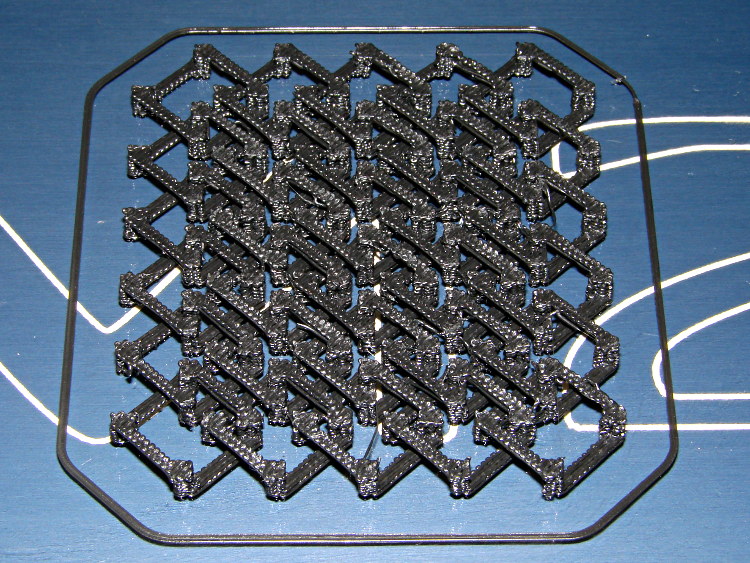
Then a pair of nested loops replicates that link across the entire fabric:

That technique didn’t work with Skeinforge (because it sent the nozzle scampering all over each layer, knocking things loose) and it didn’t work with Slic3r 0.9.8 (because it had problems with bridges), but Slic3r 0.9.10, hot from github, produced good results:
There were some strings connecting adjacent links, but a few minutes with a flush cutter solved that. Retraction was 1 mm at 80 mm/s = 480 mm/min, which seems to work fine in other contexts, but adjacent links fell inside the 1 mm minimum distance setting I’d been using. That’s now down to 0.5 mm, which should suffice for nearly everything.
The M2 sounded like I was hitting it with a hammer: each of the 480 pillar layers (!) required a quick squirt and a retraction, followed by a 500 mm/s move. Worked fine and didn’t miss a step anywhere along the way.
A view from the bottom shows it really is flexy:

I used zero perimeter threads on these tiny links, which means you can see the ripply edges of the second layer that was crosswise to the length of the link bars. Next time, I’ll try one perimeter thread, which should smooth that out.
The links stuck to the glass like they were glued, which, indeed, they were: White Rain Unscented Extra Hold Hairspray in a pump bottle (either they didn’t have Maximum Hold pump spray or I couldn’t see it). I’m not a big fan of aerosol anything and decided to try wiping the stuff across the platform glass, rather than filling the air with a fine mist and getting some on the glass. Seems to work, but more examples are needed…
The Slic3r configuration:
; generated by Slic3r 0.9.10-dev on 2013-04-17 at 17:28:11
; layer_height = 0.25
; perimeters = 0
; top_solid_layers = 3
; bottom_solid_layers = 3
; fill_density = 0.10
; perimeter_speed = 100
; infill_speed = 100
; travel_speed = 500
; nozzle_diameter = 0.35
; filament_diameter = 1.73
; extrusion_multiplier = 0.9
; perimeters extrusion width = 0.40mm
; infill extrusion width = 0.40mm
; solid infill extrusion width = 0.40mm
; top infill extrusion width = 0.40mm
The OpenSCAD source code, with the platform marker cubes expanded to cover the M2’s glass plate:
// Chain Mail Sheet
// For Slic3r and M2 printer
// Ed Nisley KE4ZNU - Apr 2013

Layout = "Build";			// Link Build

//-------
//- Extrusion parameters must match reality!
//  Print with +0 shells and 3 solid layers

ThreadThick = 0.25;
ThreadWidth = 0.40;

HoleWindage = 0.2;

Protrusion = 0.1;			// make holes end cleanly

function IntegerMultiple(Size,Unit) = Unit * ceil(Size / Unit);

//-------
// Dimensions

BarWidth = 5 * ThreadWidth;
BarThick = 3 * ThreadThick;

LinkSquare = IntegerMultiple(13.0,ThreadWidth);
LinkHeight = 2*BarThick + 1*BarThick;

LinkOutDiagonal = LinkSquare*sqrt(2) - BarWidth;
LinkInDiagonal = LinkSquare*sqrt(2) - 2*(BarWidth/2 + BarWidth*sqrt(2));

echo("Outside diagonal: ",LinkOutDiagonal);

SheetSizeX = 75;
SheetSizeY = 100;

NumLinksX = 1 + floor(SheetSizeX / LinkOutDiagonal);
NumLinksY = 1 + floor(SheetSizeY / LinkOutDiagonal);

echo("Links X: ",NumLinksX," Y: ",NumLinksY);

LinkSpacing = 0.59 * LinkOutDiagonal;

//-------

module ShowPegGrid(Space = 10.0,Size = 1.0) {

  RangeX = floor(95 / Space);
  RangeY = floor(125 / Space);

	for (x=[-RangeX:RangeX])
	  for (y=[-RangeY:RangeY])
		translate([x*Space,y*Space,Size/2])
		  %cube(Size,center=true);

}

//-------
// Create basic link

module Link() {

	rotate(45)
		difference(convexity=2) {
			translate([0,0,LinkHeight/2]) {
				difference(convexity=2) {
					intersection() {		// outside shape
						cube([LinkSquare,LinkSquare,LinkHeight],center=true);
						rotate(45)
							cube([LinkOutDiagonal,LinkOutDiagonal,LinkHeight],center=true);
					}
					intersection() {		// inside shape
						cube([(LinkSquare - 2*BarWidth),(LinkSquare - 2*BarWidth),(LinkHeight + 2*Protrusion)],center=true);
						rotate(45)
							cube([LinkInDiagonal,LinkInDiagonal,(LinkHeight +2*Protrusion)],center=true);
					}
				}
			}
			for (i=[-1,1]) {				// create bars
				translate([0,-i*(sqrt(2)*BarWidth/2),BarThick])
					rotate(45 + 180*(i+1)/2)
						cube([LinkOutDiagonal,LinkOutDiagonal,LinkHeight]);
				translate([i*(sqrt(2)*BarWidth/2),0,-BarThick])
					rotate(135 + 180*(i+1)/2)
						cube([LinkOutDiagonal,LinkOutDiagonal,LinkHeight]);
			}
		}
}

//-------
// Build it!

ShowPegGrid();

if (Layout == "Link") {
  Link();
}

if (Layout == "Build") {
	for (ix=[-(NumLinksX/2 - 0):(NumLinksX/2 - 1)])
		for (iy=[-(NumLinksY/2 - 0):(NumLinksY/2 - 1)])
			translate([ix*LinkSpacing + LinkSpacing/2,iy*LinkSpacing + LinkSpacing/2,0])
				Link();
}
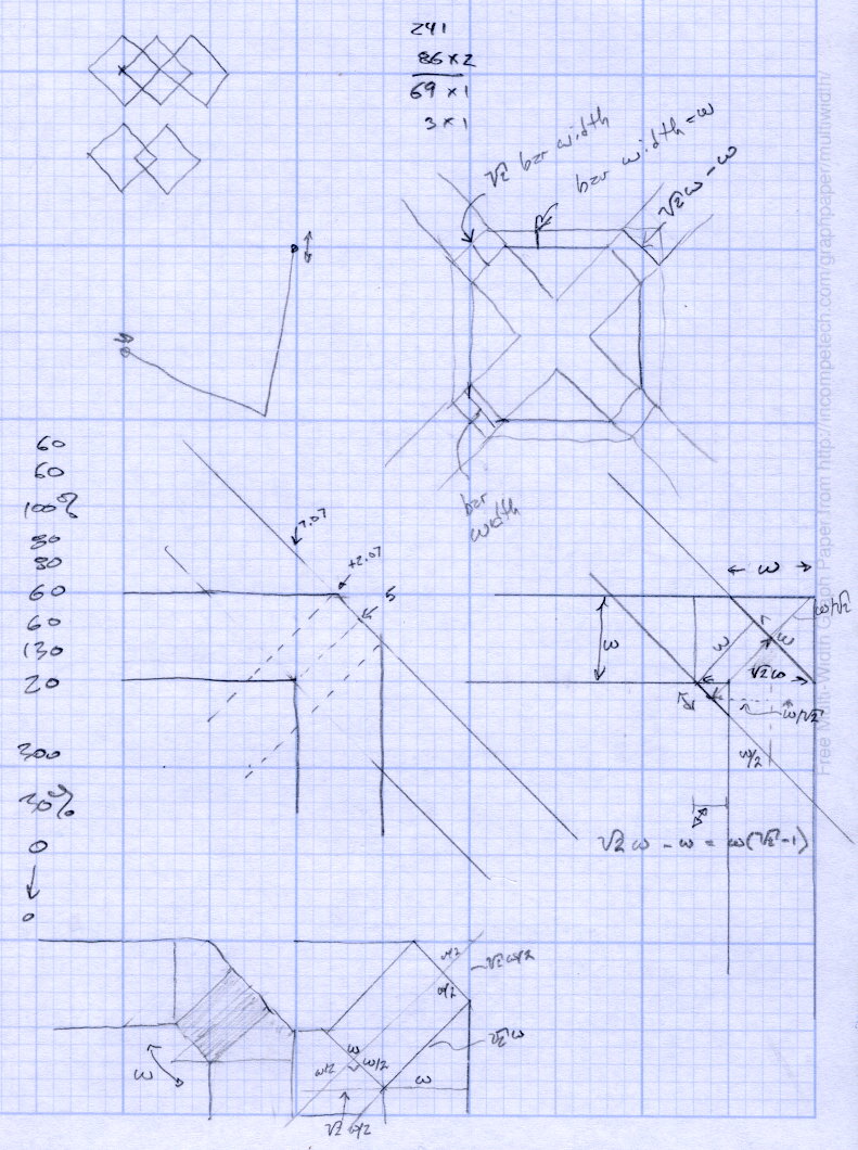
[Update: The original doodles, in case I ever need the background info:]

Comments
6 responses to “Printed Chain Mail: Subtractive Model”
Ed, I see a 3D-printed dress looming large in your future:
or a 3D-printed bikini in case you’re running low on PLA ;) (sorry, cannot find the link from couple years back)
It would definitely take a special kind of dedication to put one printed on an FDM printer on ;) The originals were Shapeway’s SLS – much smoother …
Seriously tho, your OpenSCAD sorcery does not cease to amaze me.
Cheers!
I’ll discuss this with our Larval Engineer at some appropriate moment. [grin]
Practice make, uh, pretty good! Thanks…
Hmm, I wonder what kind of ruckus someone could cause by showing up in a printed hauberk at a SCA meet. Maybe with a CNC sword? [grin]
I get the distinct impression that the SCA tolerates modern production methods for replica antique doodads, but if you can do it in the Olde Manner, that’s better.
It’s worth remembering that “to automate” means “to do something a lot cheaper that a human could do better”. I’m not sure that’s true any more, but for a long time it was…
[…] Some thoughts on rethinking a classic chainmail printed object from Thingiverse with some CAM-specific tuning to improve printing and success with resulting material from Ed Nisley: […]
[…] at the Squidwrench Show-n-Tell loved the chain mail. I printed up a sheet of Ablapo’s hexagonal chain mail before the show (because it takes […]