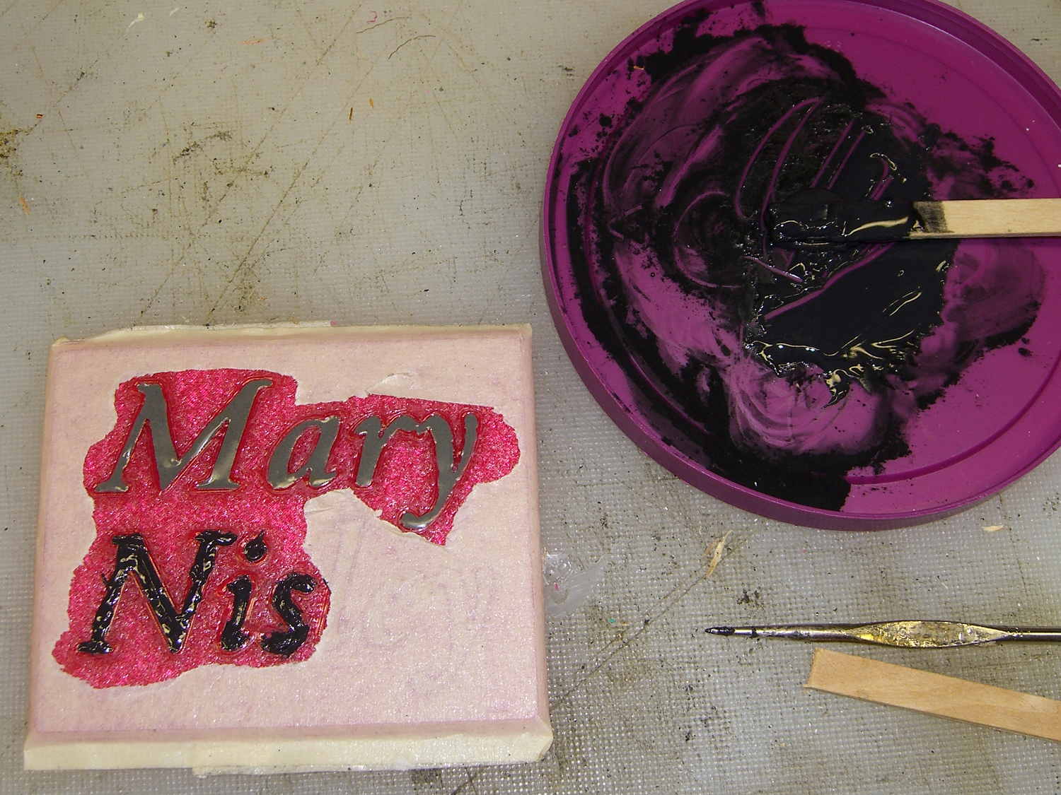
Although Mary’s name in the base of the Clover Mini Iron holder was readable in person, I wondered what filling the characters with epoxy would do. A bit of tinkering produced a name plate:
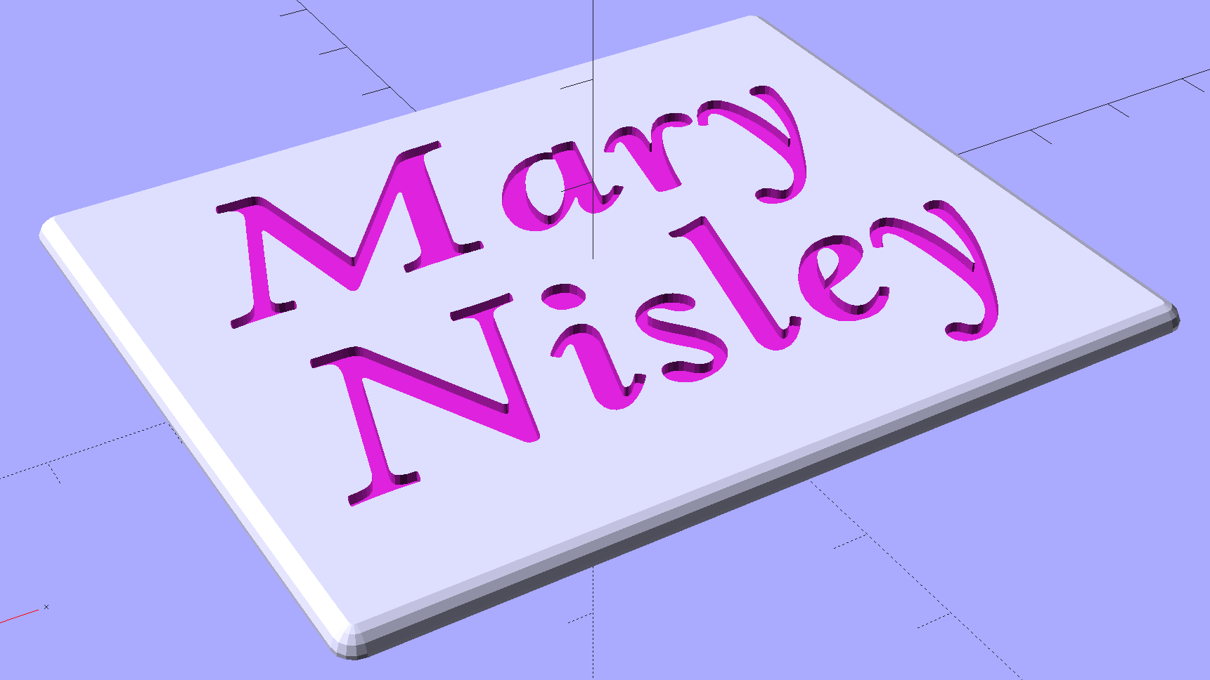
Which is more readable in person, but magenta PETG renders it basically unreadable here:
The intent of this was not to produce a lovely name block, but to see what various epoxy fills and techniques produced. Think of this as the one you must build to throw away…
I tediously filled the first line with straight JB Weld epoxy, deliberately ruining the least functional of my 1 ml syringes to ease a strand of epoxy into each letter, then poking the goo into place with a pointed rod:
That was way tedious.
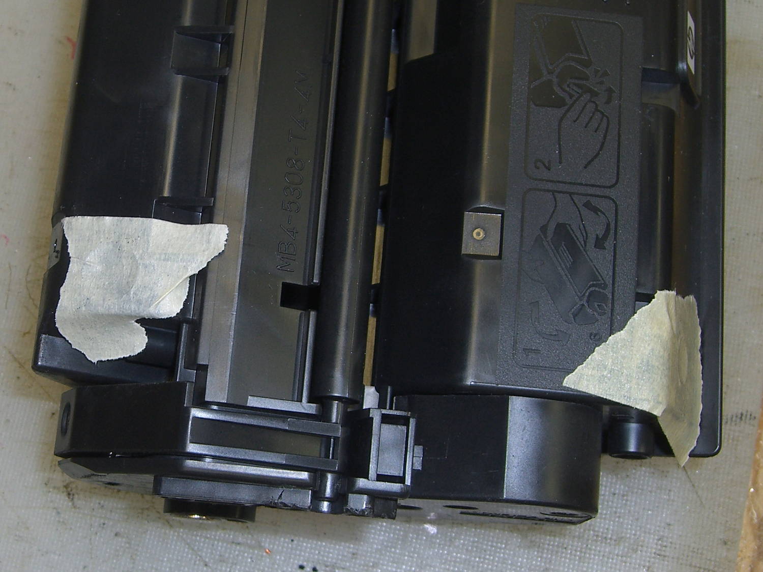
Having recently replaced the cartridge in our trusty HP Laserjet 1200, I had no qualms about step-drilling the “empty” cartridge to get the toner. For future reference, here’s where you drill into a 7115X cartridge:
I probably used too much toner, but one heaping pile on that wooden stick didn’t seem like a lot at the time:
This turned the epoxy rather thick and pasty; it didn’t ease into the letters very well at all. After the usual day, it cured into a slightly rubbery solid, quite unlike the usual rock-solid epoxy blob.
Some rummaging in the Basement Laboratory Warehouse Wing turned up two containers of aluminum powder from an Etch-a-Sketch; I mixed some into another batch of epoxy, to very little effect. With both blends, I just squished the epoxy into the letters and didn’t worry too much about slobbering any over the surface of the block.
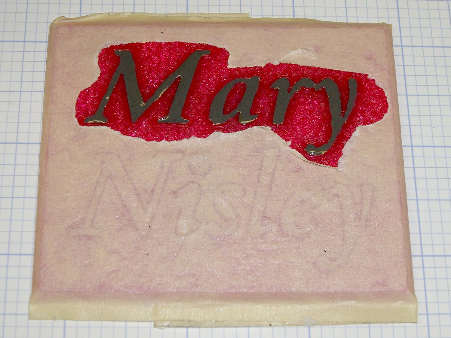
To even off the top surface, I affixed the block to the Sherline’s tooling plate with tapeless sticky (basically double-sided tape without the tape):
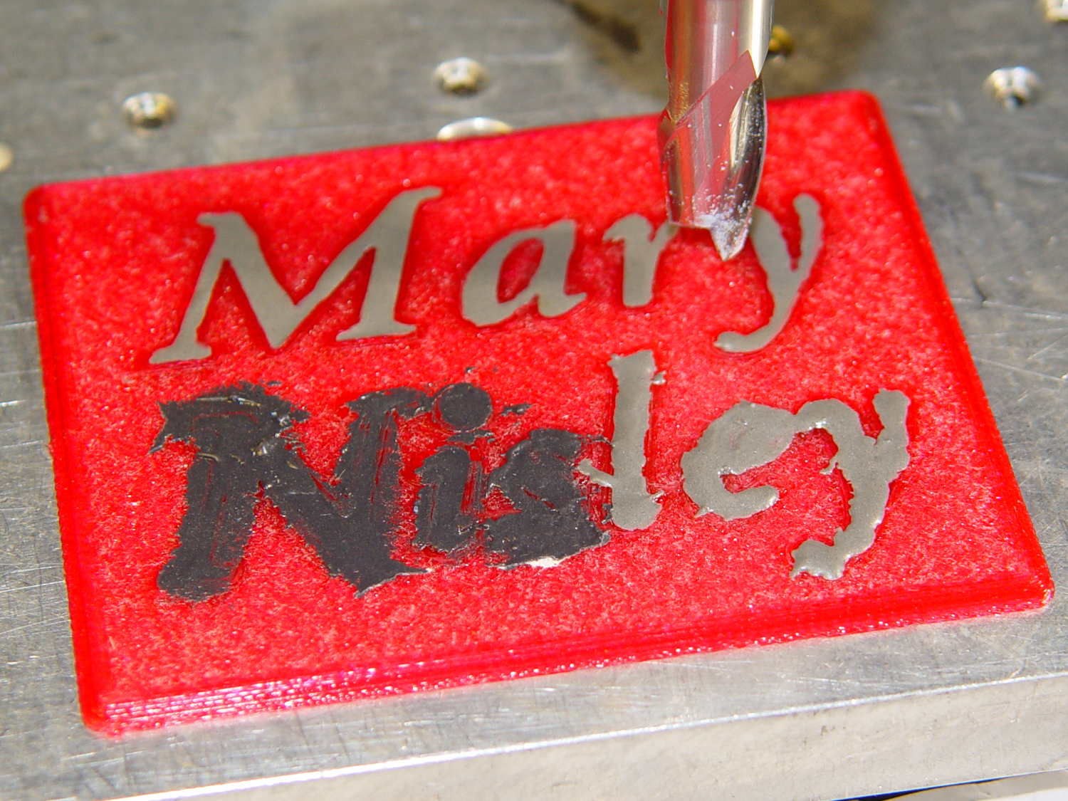
Manually traversing the surface (3 k rpm, 24 inch/min) and stepping downward about 0.1 mm per pass gradually crisped up the letters. I expected the excess epoxy to vanish after going 0.1 mm or so into the top layer, but it actually required removing the entire 0.25 mm Hilbert-curve-filled surface layer to get rid of the epoxy that soaked into / through the tiny gaps. This is 0.4 mm down from the first pass, maybe 0.1 mm into the plastic:
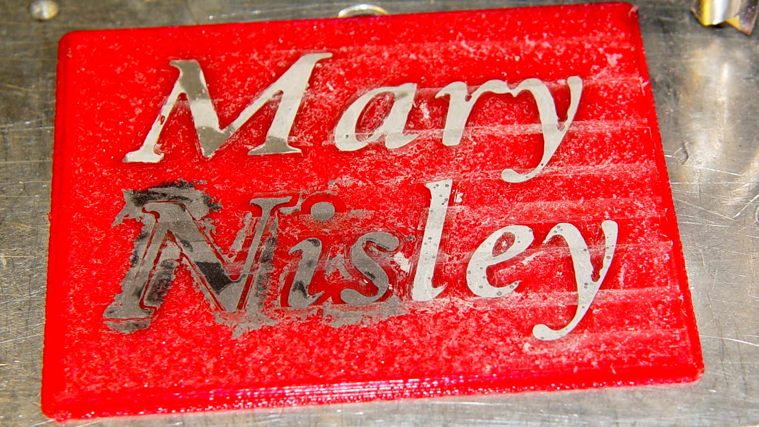
With the top layer gone, it looked rather gnarly, so I applied a sanding block that didn’t do much at all: smoother, still gnarly. Spreading maybe 0.3 ml of IPS 4 solvent adhesive over the sanded surface smoothed it a bit:

Perhaps a topcoat of clear epoxy, along the lines of XTC-3D, would produce better results.
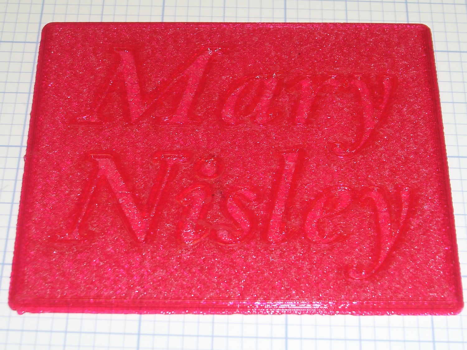
The small black dots in the top line are holes from bubbles in the epoxy. The missing section of the M started out as a bubble (just visible at 0.4 mm) and gradually enlarged as pieces tore out of the recess. There’s another bubble breaking the right stroke of the “y”.
The small dots in the “ley” are plastic spheres that carried the aluminum powder in the Etch-a-Sketch; they’re cross-sectioned and perfectly flat. The epoxy color is marginally lighter than the top line, but not enough to notice.
Backlit on a window, nearly all of the ugly fades away:
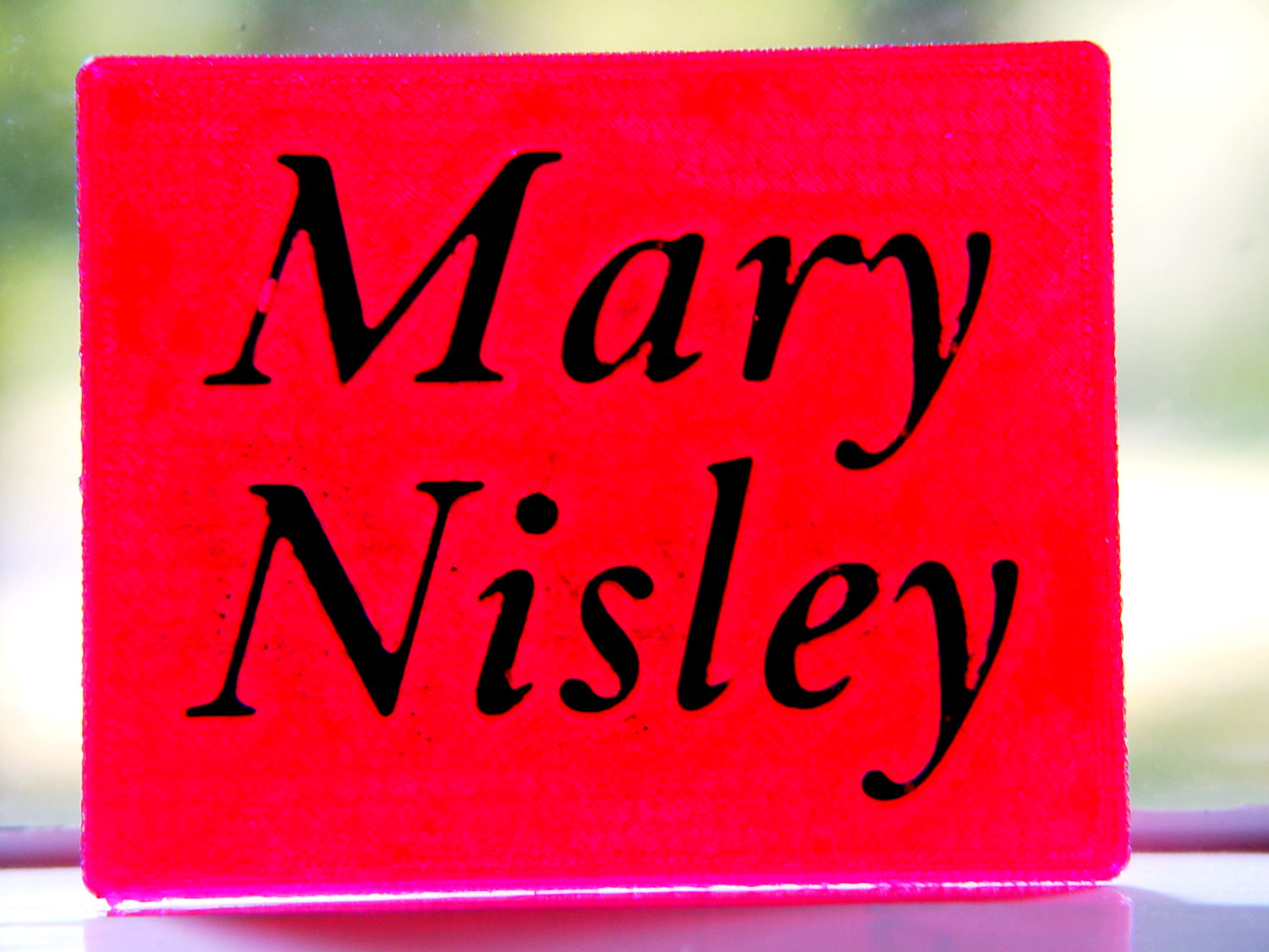
It’s definitely not presentation quality, that’s for sure, and I won’t attempt to fill the Mini Iron holder…
The OpenSCAD source code, which can also produce the soldering iron holder:
// Clover MCI-900 Mini Iron holder
// Ed Nisley KE4ZNU - August 2015

Layout = "Text";					// Iron Holder Show Text

//- Extrusion parameters - must match reality!

ThreadThick = 0.25;
ThreadWidth = 0.40;

function IntegerMultiple(Size,Unit) = Unit * ceil(Size / Unit);

Protrusion = 0.1;

HoleWindage = 0.2;

inch = 25.4;

Tap10_32 = 0.159 * inch;
Clear10_32 = 0.190 * inch;
Head10_32 = 0.373 * inch;
Head10_32Thick = 0.110 * inch;
Nut10_32Dia = 0.433 * inch;
Nut10_32Thick = 0.130 * inch;
Washer10_32OD = 0.381 * inch;
Washer10_32ID = 0.204 * inch;

//------
// Dimensions

CornerRadius = 4.0;

CenterHeight = 25;							// center at cord inlet on body

BodyLength = 110;							// cord inlet to body curve at front flange

Incline = 10;								// central angle slope

FrontOD = 29;
FrontBlock = [20,1.5*FrontOD + 2*CornerRadius,FrontOD/2 + CenterHeight + BodyLength*sin(Incline)];

CordOD = 10;
CordLen = 10;

RearOD = 22;
RearBlock = [15 + CordLen,1.5*RearOD + 2*CornerRadius,RearOD/2 + CenterHeight];

PlateWidth = 2*FrontBlock[1];

TextDepth = 4*ThreadThick;

ScrewOC = BodyLength - FrontBlock[0]/2;
ScrewDepth = CenterHeight - FrontOD/2 - 5;

echo(str("Screw OC: ",ScrewOC));

BuildSize = [200,250,200];					// largest possible thing

module PolyCyl(Dia,Height,ForceSides=0) {			// based on nophead's polyholes

  Sides = (ForceSides != 0) ? ForceSides : (ceil(Dia) + 2);

  FixDia = Dia / cos(180/Sides);

  cylinder(r=(FixDia + HoleWindage)/2,
           h=Height,
	   $fn=Sides);
}

// Trim bottom from child object

module TrimBottom(BlockSize=BuildSize,Slice=CornerRadius) {

	intersection() {
		translate([0,0,BlockSize[2]/2])
			cube(BlockSize,center=true);
		translate([0,0,-Slice])
			children();
	}
}

// Build a rounded block-like thing

module RoundBlock(Size=[20,25,30],Radius=CornerRadius,Center=false) {

	HS = Size/2 - [Radius,Radius,Radius];
	translate([0,0,Center ? 0 : (HS[2] + Radius)])
	hull() {
		for (i=[-1,1], j=[-1,1], k=[-1,1]) {
			translate([i*HS[0],j*HS[1],k*HS[2]])
				sphere(r=Radius,$fn=4*4);
		}
	}
}

// Create a channel to hold something
// This will eventually be subtracted from a block
// The offsets are specialized for this application...

module Channel(Dia,Length) {

	rotate([0,90,0])
		linear_extrude(height=Length)
			rotate(90)
				hull() {
					for (i=[-1,1])
						translate([i*Dia,2*Dia])
							circle(d=Dia/8);
					circle(d=Dia,$fn=8*4);
				}
}

// Iron-shaped series of channels to be removed from blocks

module IronCutout() {

	union() {
		translate([-2*CordLen,0,0])
			Channel(CordOD,2*CordLen + Protrusion);
		Channel(RearOD,RearBlock[0] + Protrusion);
		translate([BodyLength - FrontBlock[0]/2 - FrontBlock[0],0,0])
			Channel(FrontOD,2*FrontBlock[0]);

	}

}

module TextBlock() {
	translate([2,10,0])
		linear_extrude(height=TextDepth + Protrusion,convexity=2)		// rendering glitches for convexity > 1
//			text("Mary",font="Ubuntu:style=Bold Italic",halign="center",valign="center");
			text("Mary",font="Junicode:style=Bold Italic",halign="center",valign="center",size=20,spacing=1.05);

	translate([2,-15,0])
		linear_extrude(height=TextDepth + Protrusion,convexity=2)
			text("Nisley",font="Junicode:style=Bold Italic",halign="center",valign="center",size=20,spacing=1.05);

}

//- Build it

if (Layout == "Iron")
	IronCutout();

if (Layout == "Holder" || Layout == "Show")
	difference() {
		union() {
			translate([(BodyLength + CordLen)/2 - CordLen,0,0])
				TrimBottom()
					RoundBlock(Size=[(CordLen + BodyLength),PlateWidth,CornerRadius]);

			translate([(RearBlock[0]/2 - CordLen),0,0])
				TrimBottom()
					RoundBlock(Size=RearBlock);

			translate([BodyLength - FrontBlock[0]/2,0,0]) {
				TrimBottom()
					RoundBlock(Size=FrontBlock);
			}
		}

		translate([0,0,CenterHeight])
			rotate([0,-Incline,0])
				if (Layout == "Show")
#					IronCutout();
				else
					IronCutout();

		translate([0,0,-Protrusion])
			PolyCyl(Tap10_32,ScrewDepth + Protrusion,6);

		translate([ScrewOC,0,-Protrusion])
			PolyCyl(Tap10_32,ScrewDepth + Protrusion,6);

		translate([(RearBlock[0] - CordLen) + BodyLength/2 - FrontBlock[0],0,CornerRadius - TextDepth])
			TextBlock();

	}

if (Layout == "Text")
	difference() {
		translate([0,0,0])
			TrimBottom(Slice=8*ThreadThick)
				RoundBlock(Size=[80,65,8*ThreadThick],Radius=8*ThreadThick);
#		translate([-2,2,8*ThreadThick - TextDepth])
			TextBlock();

	}

Comments
10 responses to “Epoxy-filled 3D Printed Characters”
Next time you could try some lamination or tabletop epoxy as it is clear and much less viscous. Most lamination supply shops also stock epoxy compatible dyes. You can probably order it from http://www.jamestowndistributors.com or https://shop.fiberglasshawaii.com/ or try to find some local vendor. Incidentally, I’m quite jealous about that – it’s hard to get this stuff for a reasonable price in my corner of the world :)
The heavyweights on the LinuxCNC mailing list run their machines at 24 inch/s: obviously, I’m jealous!
Thanks…
XTC-3D is most likely relabeled tabletop epoxy, packaged in small quantities for small-time users.
I expect a relatively thin liquid would seep into and around the threads in the top few layers, because 3D printing sure doesn’t produce a “watertight” object. Perhaps sealing the surface with transparent epoxy, then filling the letters with tinted epoxy, would work. The trick would be keeping crisp edges inside the letter strokes while sealing the bottoms and sides.
The gorgeous artifacts produced by folks on the M2 forums show what’s possible…
What I have done with my laser or CNC is to engrave the block with the letters I want, then cut the same letters out with a thin piece of wood and inset it. Would be interesting to try that with multiple colors in plastic? You would trade all of the facing and sanding work for 3d filament change work, so probably a net 0, but if you planned ahead…. Or simply print the letters out in the same color and paint them prior to snapping them in. Make them thicker so they sit a little proud, textures, etc…. Just some ideas.
Or simply get a dual printhead. They seem to work pretty good these days :)
E3D even makes some that should be almost idiot proof as they combine single nozzle with two filament in-feeds. Since melt chamber is rather small you get fast color changes simply by feeding from other feeder. Well, in theory at least, I’ve never tried one.
My self-sourced Ultimaker is still not capable of this -> https://ultimaker.com/en/community/view/10657-a-different-multi-extrusion-approach-um-tool-printhead-changer
, but hotend changer thingy is definitely lurking somewhere in it’s future :)
The bone-stock M2 dual extruder reduces the X-axis travel by a goodly chunk and, for me, seems a poor tradeoff for something I really don’t need all that often. The Cyclops dual extruder makes sense, although it sure looks like it’s way out on the experimental end: I’d want plenty of evidence that it works under real-world conditions. [grin]
Actually, it doesn’t. The left extruder can traverse the entire width of the bed. Only the right extruder is limited from accessing maybe 30mm on the left.
Point taken, but …
Aye! That would certainly produce a cleaner result with less annoyance. I’d have to fiddle around with the tolerances to get everything to fit properly, but that’s in the nature of fine tuning.
Having the letters stick out a bit would simplify handling those little parts. Good idea!
I’ve done some embossed filling experiments myself. I used ABS slurry in a PLA body. It turned out okay with some sanding, but the dried ABS ended up with many bubbles: http://forum.makergear.com/viewtopic.php?f=2&t=1206
You could do a multicolored print if you extruded the letters out for a few layers, then did a separate print. Although that might not work for you since you home right on top of your print area. You could do it in a single print with some g-code assisted filament swapping, I saw a thread going over the specifics of that in the forum. The trick is to make sure the absolute E coordinate is retained properly through all the backing and purging.
For smoothing, I’ve read that a heat gun can be used to good effect. Don’t own a heat gun, but perhaps you do.
You’re my role model for that stuff…
The least-awful / lowest-labor lettering seems to involve extending the characters upward by a few layers, then doing an on-the-fly filament change as the nozzle starts the first layer. That actually worked on the chain mail, although poking the filament into that teeny hole on a moving extruder poses a bit of a challenge.
Next time, for sure… [grin]