The Smell of Molten Projects in the Morning

Ed Nisley's Blog: Shop notes, electronics, firmware, machinery, 3D printing, laser cuttery, and curiosities. Contents: 100% human thinking, 0% AI slop.

Tag: CNC

Making parts with mathematics

  • Vacuum Tube LEDs: Ersatz Tube Sockets

    Even vacuum tubes destined to be decorations need sockets:
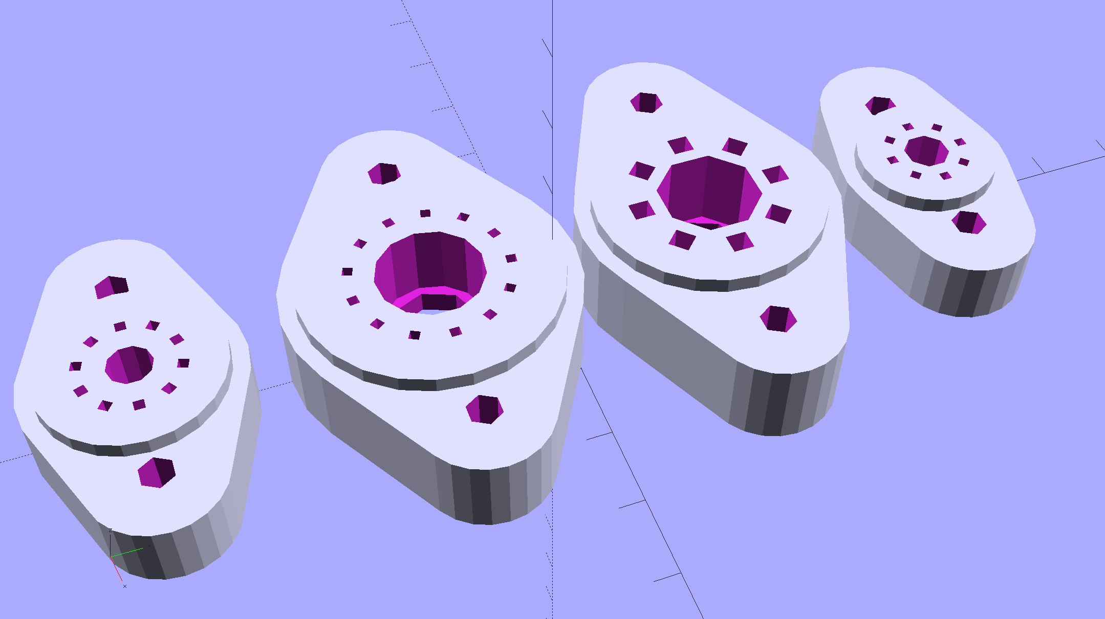
    Vacuum Tube Bases - solid models
    Vacuum Tube Bases – solid models

    They’re entirely plastic, of course, but they match the dimensions of “real” tube sockets pretty closely. The bosses around the pins have hard-inch dimensions, so you (well, I) can unleash Genuine Greenlee Radio Chassis Punches on sheet metal.

    All the key dimensions come from a table, so you can build whatever sockets you need. These four seem to cover the most common relics of the Hollow State Empire:

    T_NAME = 0;                                             // common name
    T_NUMPINS = 1;                                          // total, with no allowance for keying
    T_PINBCD = 2;                                           // tube pin circle diameter
    T_PINOD = 3;                                            //  ... diameter
    T_PINLEN = 4;                                           //  ... length (overestimate)
    T_HOLEOD = 5;                                           // nominal panel hole from various sources
    T_PUNCHOD = 6;                                          // panel hole optimized for inch-size Greenlee punches
    T_TUBEOD = 7;                                           // envelope or base diameter
    T_PIPEOD = 8;                                           // light pipe from LED to tube base
    T_SCREWOC = 9;                                          // mounting screw holes
    
    //    Name      pins     BCD   dia  length   hole            punch       env  pipe screw
    TubeData = [
        ["Mini7",     8,    9.53, 1.016,   7.0,  16.0,        11/16 * inch,  18.0,  5.0, 22.5],
        ["Octal",     8,   17.45, 2.36,   10.0,  36.2,    (8 + 1)/8 * inch,  32.0, 11.5, 39.0],
        ["Noval",    10,   11.89, 1.1016,  7.0,  22.0,          7/8 * inch,  21.0,  5.0, 28.0],
        ["Duodecar", 13,   19.10, 1.05,    9.0,  32.0,         1.25 * inch,  38.0, 12.5, 39.0],
    ];
    

    Given that the tubes lack electrical connections, I omitted the base keying: plug them in for best visual effect.

    The hole through the middle passes light from a knockoff Neopixel on a 10 mm OD PCB:
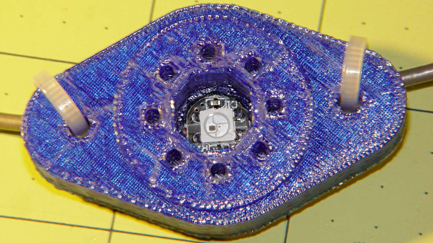
    Vacuum Tube LEDs - Octal base - top
    Vacuum Tube LEDs – Octal base – top

    Seen from the bottom, each base traps a pair of 6-32 nuts for chassis mounting and has a Neopixel press-fit in the middle:

    Vacuum Tube LEDs - Duodecar base - bottom
    Vacuum Tube LEDs – Duodecar base – bottom

    Those recesses require support structures:

    Vacuum Tube Bases - solid models - support
    Vacuum Tube Bases – solid models – support

    The Miniature 7-pin socket has the least space for the 10 mm OD Neopixel PCB and shows the thin layer between the bottom of the pin holes and the top of the openings.
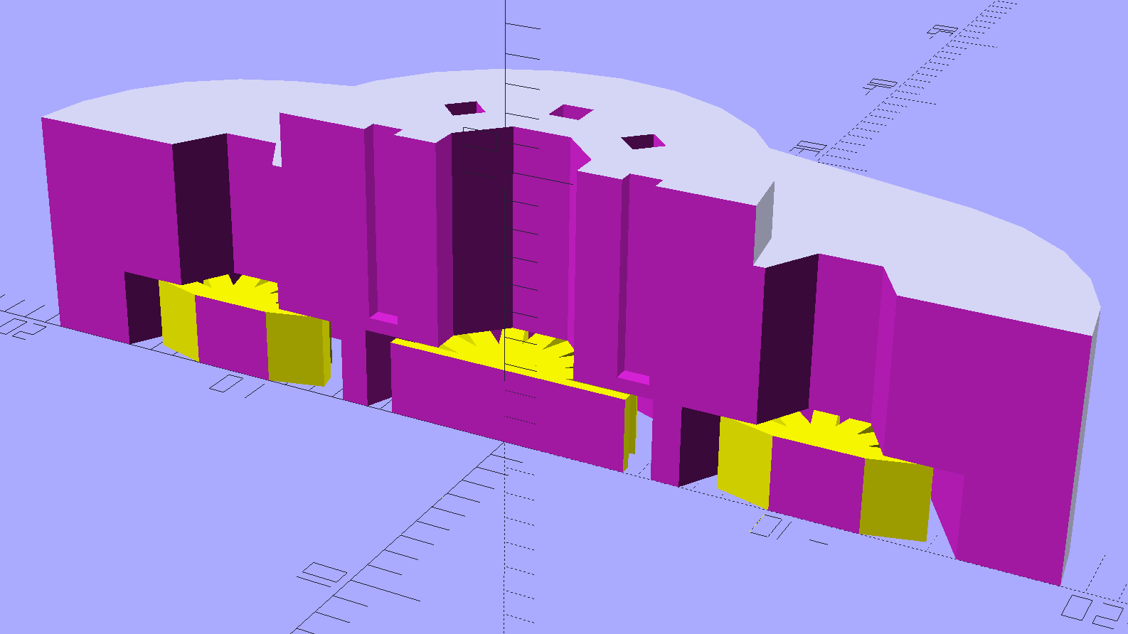
    Vacuum Tube Base - Mini7 - solid model section
    Vacuum Tube Base – Mini7 – solid model section

    You see half of the eight holes in the “7 pin” socket, because it has the eighth hole where a standard socket has a gap between pins 1 and 7.

    Somewhat to my surprise, punching the support spiders out with a 6-32 stud (grabbed in the drill press) worked perfectly:
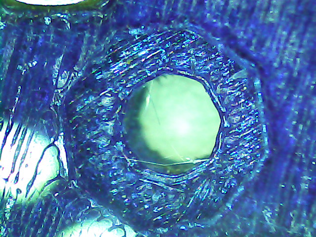
    Vacuum Tube Base - nut trap overhang - detail
    Vacuum Tube Base – nut trap overhang – detail

    They look like I intended to build tiny decorations:
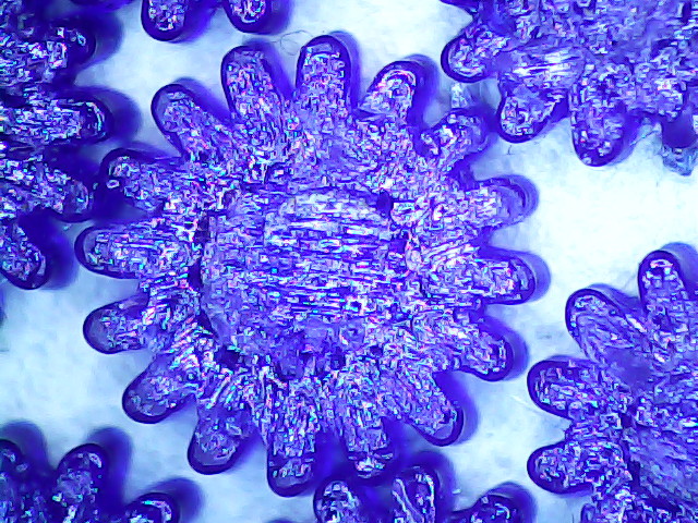
    Vacuum Tube Base - support structure - detail
    Vacuum Tube Base – support structure – detail

    The cookies held on tenuously, then released with a loud bang! as I gradually increased the pressure. A PETG support structure in a blind recess wouldn’t pop out nearly so well.

    The OpenSCAD source code as a GitHub gist:

    // Vacuum Tube LED Lights
    // Ed Nisley KE4ZNU January 2016
    Layout = "Sockets"; // Cap LampBase USBPort Socket(s)
    Section = true; // cross-section the object
    Support = true;
    //- Extrusion parameters must match reality!
    ThreadThick = 0.25;
    ThreadWidth = 0.40;
    HoleWindage = 0.2;
    Protrusion = 0.1; // make holes end cleanly
    inch = 25.4;
    function IntegerMultiple(Size,Unit) = Unit * ceil(Size / Unit);
    //———————-
    // Dimensions
    // https://en.wikipedia.org/wiki/Tube_socket#Summary_of_Base_Details
    T_NAME = 0; // common name
    T_NUMPINS = 1; // total, with no allowance for keying
    T_PINBCD = 2; // tube pin circle diameter
    T_PINOD = 3; // … diameter
    T_PINLEN = 4; // … length (overestimate)
    T_HOLEOD = 5; // nominal panel hole from various sources
    T_PUNCHOD = 6; // panel hole optimized for inch-size Greenlee punches
    T_TUBEOD = 7; // envelope or base diameter
    T_PIPEOD = 8; // light pipe from LED to tube base
    T_SCREWOC = 9; // mounting screw holes
    // Name pins BCD dia length hole punch env pipe screw
    TubeData = [
    ["Mini7", 8, 9.53, 1.016, 7.0, 16.0, 11/16 * inch, 18.0, 5.0, 22.5],
    ["Octal", 8, 17.45, 2.36, 10.0, 36.2, (8 + 1)/8 * inch, 32.0, 11.5, 39.0],
    ["Noval", 10, 11.89, 1.1016, 7.0, 22.0, 7/8 * inch, 21.0, 5.0, 28.0],
    ["Duodecar", 13, 19.10, 1.05, 9.0, 32.0, 1.25 * inch, 38.0, 12.5, 39.0],
    ];
    ID = 0;
    OD = 1;
    LENGTH = 2;
    Pixel = [7.0,10.0,3.0]; // ID = contact patch, OD = PCB dia, LENGTH = overall thickness
    Nut = [3.5,8.0,3.0]; // socket mounting nut recess
    BaseShim = 2*ThreadThick; // between pin holes and pixel top
    SocketFlange = 2.0; // rim around socket below punchout
    PanelThick = 2.0; // socket extension through punchout
    //———————-
    // Useful routines
    module PolyCyl(Dia,Height,ForceSides=0) { // based on nophead's polyholes
    Sides = (ForceSides != 0) ? ForceSides : (ceil(Dia) + 2);
    FixDia = Dia / cos(180/Sides);
    cylinder(r=(FixDia + HoleWindage)/2,h=Height,$fn=Sides);
    }
    //———————-
    // Tube cap
    CapTube = [4.0,3/16 * inch,10.0]; // brass tube for flying lead to cap LED
    CapSize = [Pixel[ID],(Pixel[OD] + 3.0),(CapTube[OD] + 2*Pixel[LENGTH])];
    CapSides = 6*4;
    module Cap() {
    difference() {
    union() {
    cylinder(d=CapSize[OD],h=(CapSize[LENGTH]),$fn=CapSides); // main cap body
    translate([0,0,CapSize[LENGTH]]) // rounded top
    scale([1.0,1.0,0.65])
    sphere(d=CapSize[OD]/cos(180/CapSides),$fn=CapSides); // cos() fixes slight undersize vs cylinder
    cylinder(d1=(CapSize[OD] + 2*3*ThreadWidth),d2=CapSize[OD],h=1.5*Pixel[LENGTH],$fn=CapSides); // skirt
    }
    translate([0,0,-Protrusion]) // bore for wiring to LED
    PolyCyl(CapSize[ID],(CapSize[LENGTH] + 3*ThreadThick + Protrusion),CapSides);
    translate([0,0,-Protrusion]) // PCB recess with clearance for tube dome
    PolyCyl(Pixel[OD],(1.5*Pixel[LENGTH] + Protrusion),CapSides);
    translate([0,0,(1.5*Pixel[LENGTH] – Protrusion)]) // small step + cone to retain PCB
    cylinder(d1=(Pixel[OD]/cos(180/CapSides)),d2=Pixel[ID],h=(Pixel[LENGTH] + Protrusion),$fn=CapSides);
    translate([0,0,(CapSize[LENGTH] – CapTube[OD]/(2*cos(180/8)))]) // hole for brass tube holding wire loom
    rotate([90,0,0]) rotate(180/8)
    PolyCyl(CapTube[OD],CapSize[OD],8);
    }
    }
    //———————-
    // Aperture for USB-to-serial adapter snout
    // These are all magic numbers, of course
    module USBPort() {
    translate([0,28.0])
    rotate([90,0,0])
    linear_extrude(height=28.0)
    polygon(points=[
    [0,0],
    [8.0,0],
    [8.0,4.0],
    // [4.0,4.0],
    [4.0,6.5],
    [-4.0,6.5],
    // [-4.0,4.0],
    [-8.0,4.0],
    [-8.0,0],
    ]);
    }
    //———————-
    // Box for Leviton ceramic lamp base
    module LampBase() {
    Bottom = 3.0;
    Base = [4.0*inch,4.5*inch,20.0 + Bottom];
    Sides = 12*4;
    Retainer = [3.5,11.0,1.0]; // flat fiber washer holding lamp base screws in place
    StudSides = 8;
    StudOC = 3.5 * inch;
    Stud = [0.107 * inch, // 6-32 mounting screws
    min(15.0,1.5*(Base[ID] – StudOC)/cos(180/StudSides)), // OD = big enough to merge with walls
    (Base[LENGTH] – Retainer[LENGTH])]; // leave room for retainer
    union() {
    difference() {
    rotate(180/Sides)
    cylinder(d=Base[OD],h=Base[LENGTH],$fn=Sides);
    rotate(180/Sides)
    translate([0,0,Bottom])
    cylinder(d=Base[ID],h=Base[LENGTH],$fn=Sides);
    translate([0,-Base[OD]/2,Bottom + 1.2]) // mount on double-sided foam tape
    rotate(0)
    USBPort();
    }
    for (i = [-1,1])
    translate([i*StudOC/2,0,0])
    rotate(180/StudSides)
    difference() {
    # cylinder(d=Stud[OD],h=Stud[LENGTH],$fn=StudSides);
    translate([0,0,Bottom])
    PolyCyl(Stud[ID],(Stud[LENGTH] – (Bottom – Protrusion)),6);
    }
    }
    }
    //———————-
    // Tube Socket
    module Socket(Name = "Mini7") {
    NumSides = 6*4;
    Tube = search([Name],TubeData,1,0)[0];
    echo(str("Building ",TubeData[Tube][0]," socket"));
    echo(str(" Punch: ",TubeData[ID][T_PUNCHOD]," mm = ",TubeData[ID][T_PUNCHOD]/inch," inch"));
    echo(str(" Screws: ",TubeData[ID][T_SCREWOC]," mm =",TubeData[ID][T_SCREWOC]/inch," inch OC"));
    OAH = Pixel[LENGTH] + BaseShim + TubeData[Tube][T_PINLEN];
    BaseHeight = OAH – PanelThick;
    difference() {
    union() {
    linear_extrude(height=BaseHeight)
    hull() {
    circle(d=(TubeData[Tube][T_PUNCHOD] + 2*SocketFlange),$fn=NumSides);
    for (i=[-1,1])
    translate([i*TubeData[Tube][T_SCREWOC]/2,0])
    circle(d=2*Nut[OD],$fn=NumSides);
    }
    cylinder(d=TubeData[Tube][T_PUNCHOD],h=OAH,$fn=NumSides);
    }
    for (i=[0:(TubeData[Tube][T_NUMPINS] – 1)]) // tube pins
    rotate(i*360/TubeData[Tube][T_NUMPINS])
    translate([TubeData[Tube][T_PINBCD]/2,0,(OAH – TubeData[Tube][T_PINLEN])])
    rotate(180/4)
    PolyCyl(TubeData[Tube][T_PINOD],(TubeData[Tube][T_PINLEN] + Protrusion),4);
    for (i=[-1,1]) // mounting screw holes & nut traps
    translate([i*TubeData[Tube][T_SCREWOC]/2,0,-Protrusion]) {
    PolyCyl(Nut[OD],(Nut[LENGTH] + Protrusion),6);
    PolyCyl(Nut[ID],(OAH + 2*Protrusion),6);
    }
    translate([0,0,-Protrusion]) { // LED recess
    PolyCyl(Pixel[OD],(Pixel[LENGTH] + Protrusion),8);
    }
    translate([0,0,(Pixel[LENGTH] – Protrusion)]) { // light pipe
    rotate(180/TubeData[Tube][T_NUMPINS])
    PolyCyl(TubeData[Tube][T_PIPEOD],(OAH + 2*Protrusion),TubeData[Tube][T_NUMPINS]);
    }
    }
    // Totally ad-hoc support structures …
    if (Support) {
    color("Yellow") {
    for (i=[-1,1]) // nut traps
    translate([i*TubeData[Tube][T_SCREWOC]/2,0,(Nut[LENGTH] – ThreadThick)/2])
    for (a=[0:5])
    rotate(a*30 + 15)
    cube([2*ThreadWidth,0.9*Nut[OD],(Nut[LENGTH] – ThreadThick)],center=true);
    if (Pixel[OD] > TubeData[Tube][T_PIPEOD]) // support pipe only if needed
    translate([0,0,(Pixel[LENGTH] – ThreadThick)/2])
    for (a=[0:7])
    rotate(a*22.5)
    cube([2*ThreadWidth,0.9*Pixel[OD],(Pixel[LENGTH] – ThreadThick)],center=true);
    }
    }
    }
    //———————-
    // Build it
    if (Layout == "Cap") {
    if (Section)
    difference() {
    Cap();
    translate([-CapSize[OD],0,CapSize[LENGTH]])
    cube([2*CapSize[OD],2*CapSize[OD],3*CapSize[LENGTH]],center=true);
    }
    else
    Cap();
    }
    if (Layout == "LampBase")
    LampBase();
    if (Layout == "USBPort")
    USBPort();
    if (Layout == "Socket")
    if (Section) {
    difference() {
    Socket();
    translate([-100/2,0,-Protrusion])
    cube([100,50,50],center=false);
    }
    }
    else
    Socket();
    if (Layout == "Sockets") {
    translate([0,50,0])
    Socket("Mini7");
    translate([0,20,0])
    Socket("Octal");
    translate([0,-15,0])
    Socket("Duodecar");
    translate([0,-50,0])
    Socket("Noval");
    }


  • Knurled Metric Inserts

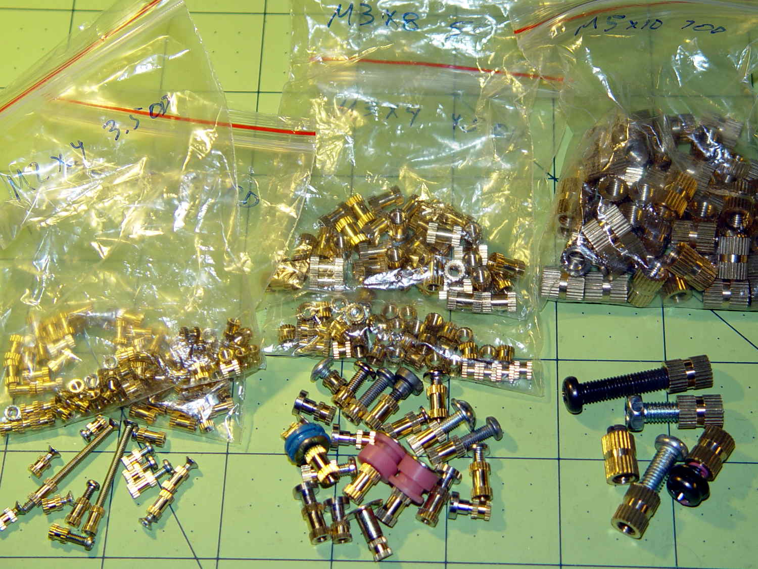
    These seem like they ought to come in handy for fastening things to 3D printed objects:

    Kurled Inserts - M2 M3 M5
    Kurled Inserts – M2 M3 M5

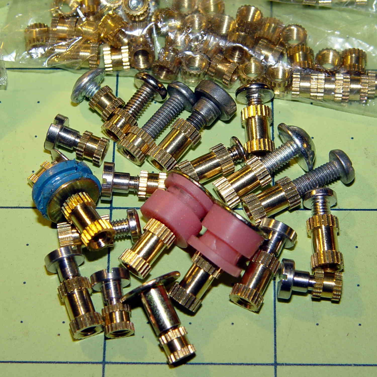
    The assorted screws come from the Small Can o’ Small Screwlike Things, all harvested from various dead bits of consumer electronics:

    Kurled M3 Inserts
    Kurled M3 Inserts

    These would benefit from a heated staking tool that slides them into the hole parallel to the axis and flush with the surface. Such things are commercially available, of course, but for my simple needs something involving a cartridge heater, a wall wart, and a drill press may suffice.

    It would be better if the inserts had actual knurls, rather than splines. So it goes.

    For the record (thread x length x Knurl OD x Body OD):

    • M2 x 4 x 3.5 x 2.8
    • M2 x 6 x 3.5 x 2.7
    • M3 x 4 x 4.5 x 3.8
    • M3 x 8 x 5.0 x 3.9
    • M5 x 10 x 7.5 x 6.9

    The actual measurements seem to vary within ±0.02 of nominal and I doubt the manufacturing consistency justifies any assumption tighter than ±0.1 mm.

    The M3 inserts really do have two different ODs.

    The M5 insert was listed as “7 mm OD” and measures 7.5 mm, which suggests a typo in the description.

    The polygonal hole adjustment I use produces dead-on diameters for small vertical holes:

    HoleWindage = 0.2;
    
    module PolyCyl(Dia,Height,ForceSides=0) {	// based on nophead's polyholes
      Sides = (ForceSides != 0) ? ForceSides : (ceil(Dia) + 2);
      FixDia = Dia / cos(180/Sides);
      cylinder(d=(FixDia + HoleWindage),h=Height,$fn=Sides);
    }
    

    So an ordinary cylinder() with the nominal knurl OD or a PolyCyl() with the nominal body OD should suffice. Horizontal holes can probably use a plain old cylinder() with the nominal body OD, because they need reaming anyway.

    Perhaps a dab of epoxy would bond better with the plastic around a nominal-size hole than forcing the insert into an undersized hole or heat-bonding the insert. Some experimentation is in order.

    Ten bucks for the entire collection (five bags of 50 inserts each = 250 little brass doodads = 4¢ each), shipped free halfway around the planet, seemed reasonable, given that inch size knurled brass inserts run anywhere from 50¢ to upwards of $2 a pop and a Genuine Helicoil 4-40 insert sets you back just shy of a buck.

    An Amazon vendor offers 4-40 inserts for $0.24 each in single quantities, but with $9.25 shipping. [le sigh]

    Inch-size inserts with knurled rings intended for ultrasonic bonding seem to be 5¢ to 15¢ on eBay. I think the straight-side versions will work better than the tapered ones for heat or epoxy bonding.

    It knurls my knuckles that we here in the US haven’t gone solidly metric. Yes, I have a goodly assortment of metric hardware in addition to the harvested fasteners shown above, but it definitely wasn’t cheap & readily available.

  • Ham It Up Noise Source Enable Switch

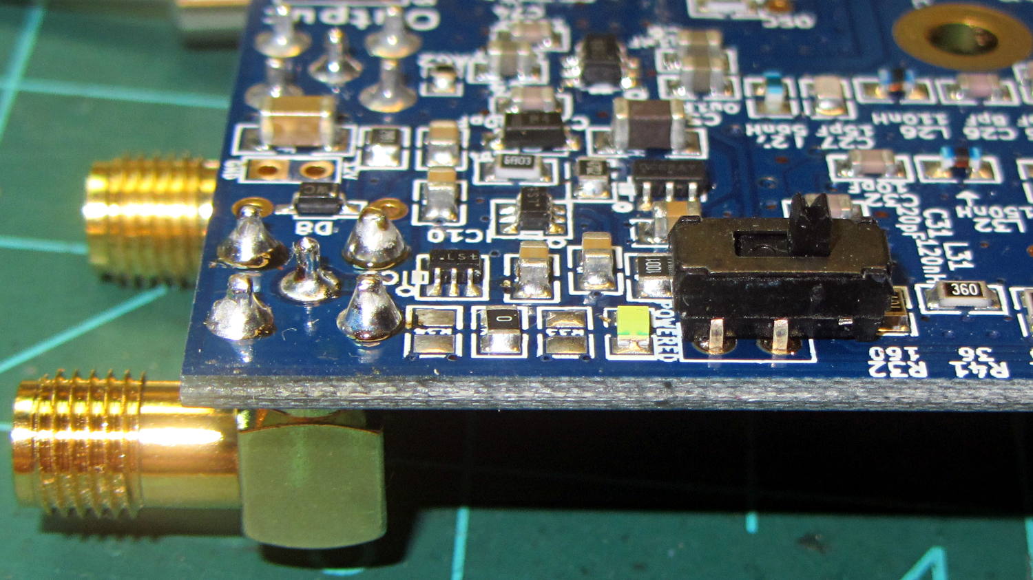
    Some rummaging produced a tiny DPDT switch that actually fit the holes intended for a pin header on the recently arrived Ham It Up board, at least after I amputated 2/3 of the poor thing’s legs:

    Ham-It-Up - noise source switch - B
    Ham-It-Up – noise source switch – B

    The new SMA noise output jack sits in the front left, with the white “noise on” LED just left of the switch:

    Ham-It-Up - noise source switch - A
    Ham-It-Up – noise source switch – A

    There’s no way to measure these things accurately, at least as far as I can tell, but the holes came out pretty close to where they should be. The new SMA connector lined up horizontally with the existing IF output jack and vertically with the measured / rounded-to-the-nearest-millimeter on-center distance:

    Ham It Up - noise SMA drilling
    Ham It Up – noise SMA drilling

    The Enable switch doesn’t quite line up with the LED, so the holes will always look like I screwed up:

    Ham-It-Up - noise source switch - case holes
    Ham-It-Up – noise source switch – case holes

    That’s OK, nobody will ever notice.

    Now, to stack up enough adapters to get from the SMA on the Ham It Up board to the N connector on the spectrum analyzer …


  • Slic3r vs. Sequential 3D Printing

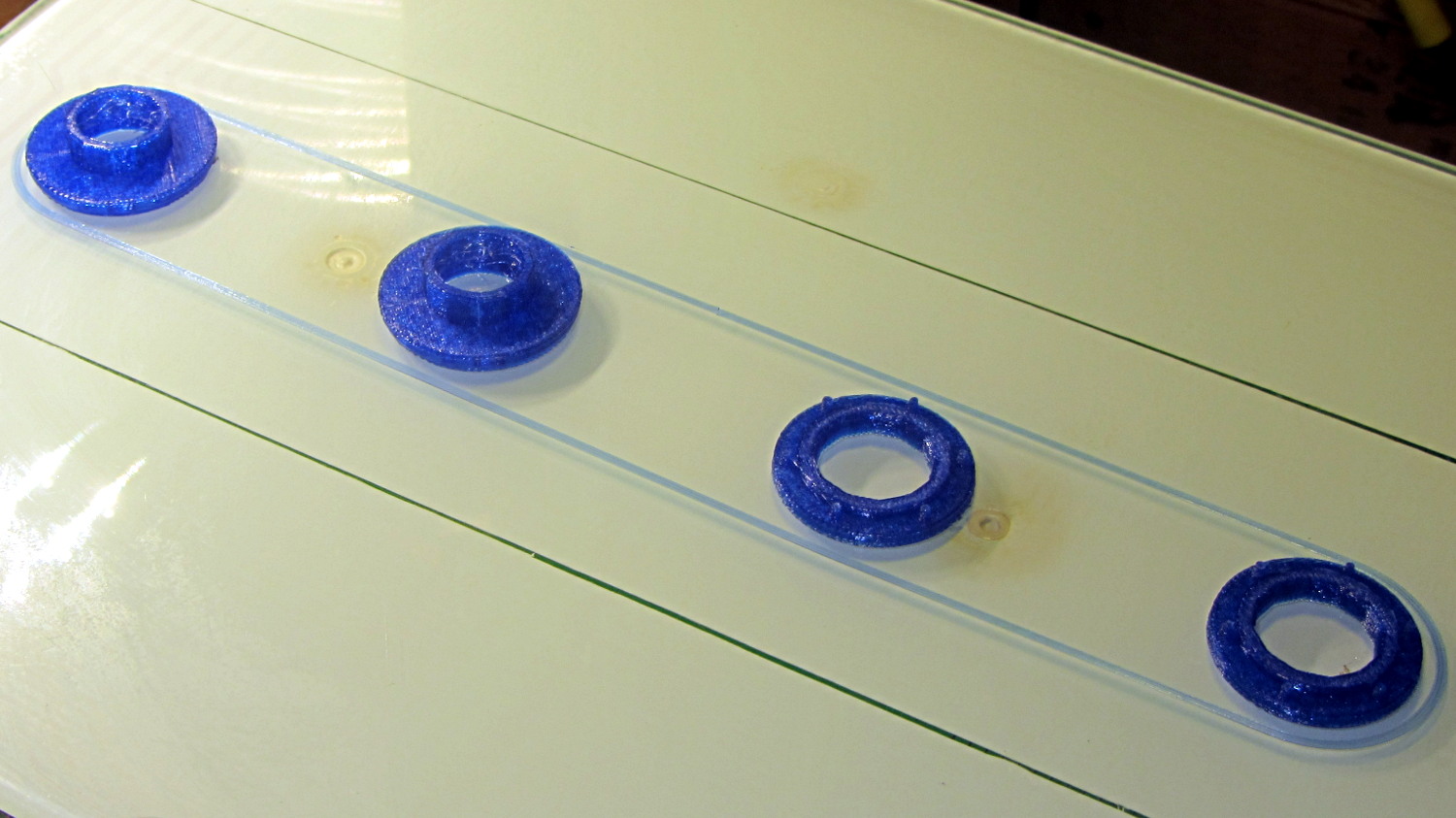
    The tiny posts on the fencing helmet ear grommet produced a remarkable amount of PETG hair, because the nozzle had to skip between four separate pieces on the platform at each layer:

    So I told Slic3r to build each part separately:

    Fencing helmet grommet - separate builds - first attempt
    Fencing helmet grommet – separate builds – first attempt

    Due to absolutely no forethought or planning on my part, that actually worked. Slic3r defines a cylindrical keep-out zone around the nozzle that I set to 15 mm radius and 25 mm height, but those numbers are completely wrong for the M2, particularly with a V4 hot end.

    To the rear, the nuts & bolts along the bottom of the X gantry sit 5 mm above the V4 nozzle, with the relaxed actuator on my re-relocated Z-axis home switch at Z=+1 mm:

    V4 PETG - extruder priming
    V4 PETG – extruder priming

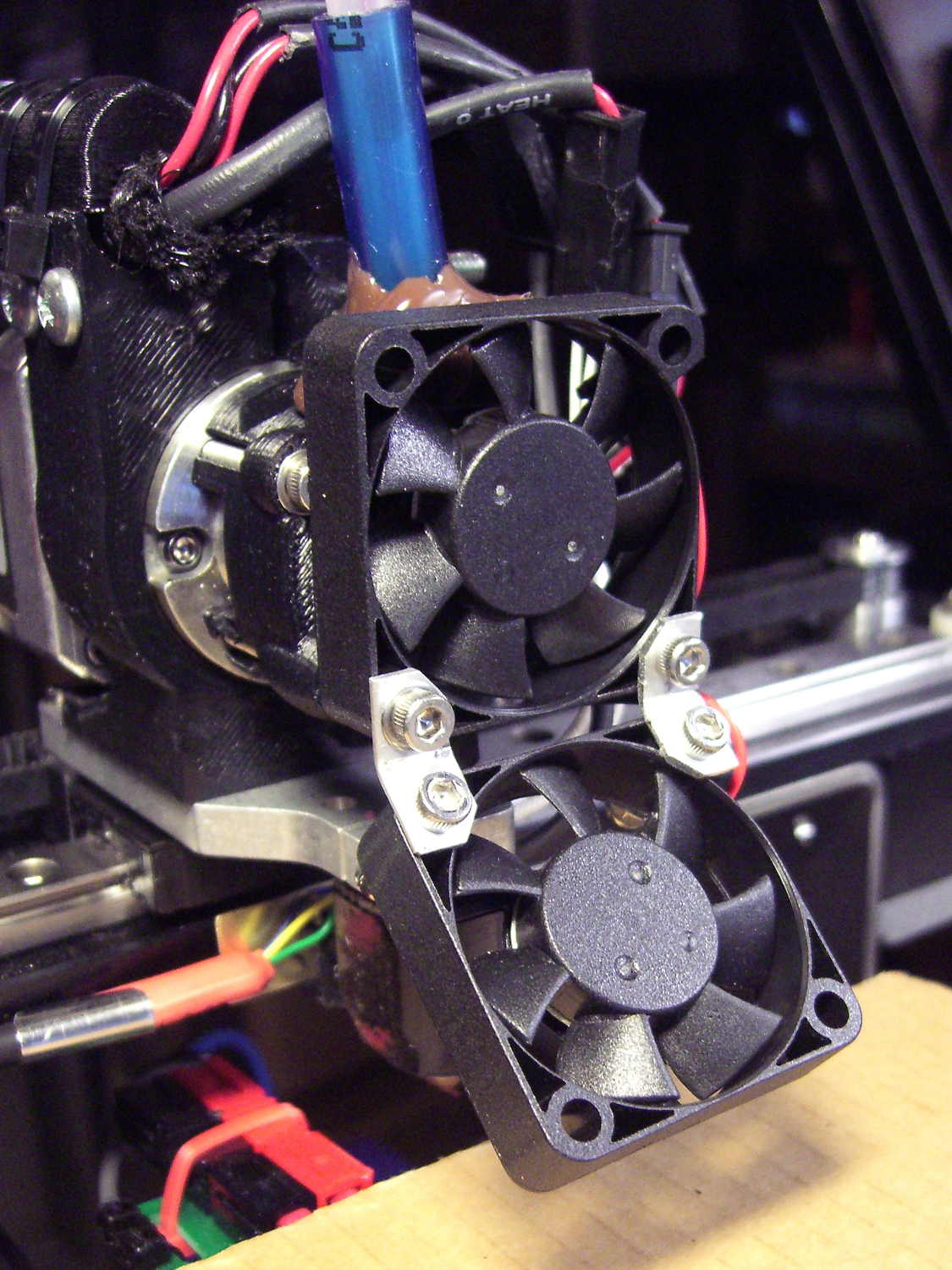
    To the front, the bed fan doesn’t sit much higher:

    M2 V4 Extruder - 24 V fans
    M2 V4 Extruder – 24 V fans

    As it turned out, the front washers built first, sitting there in front of the gantry and behind the fan, the rear washers appeared last, and Everything Just Worked.

    However, even though the M2’s layout won’t allow for automated layout, I figured I could do it manually by building the parts from front to rear:

    Fencing Helmet Ear Grommet - Slic3r layout
    Fencing Helmet Ear Grommet – Slic3r layout

    That way, the already-built parts never pass under the gantry / switch. For particularly tall parts, I could remove / relocate the bed fan to clear the already-built parts as they appear.

    Come to find out that Slic3r, for whatever reason, doesn’t build the parts in the order you’d expect from the nice list on the far right side of the screen:

    Sequential Build Order - Slic3r vs Pronterface
    Sequential Build Order – Slic3r vs Pronterface

    Worse, the Slic3r 3D preview shows the threads by layer (which is what you’d expect), rather than by object for sequential builds:

    Slic3r - sequential preview vs build order
    Slic3r – sequential preview vs build order

    I don’t know how you’d force-fit a four-dimensional preview into the UI, so I won’t complain at all.

    There’s no way to tell which part will build first; selecting the part will highlight its entry in the list (and vice versa), but the order of appearance in that list doesn’t tell you where the G-Code will appear in the output file. That’s not a problem for extruders with a keep-out volume that looks like a cylinder, so there’s no reason for Slic3r to do it any differently: it will manage the extruder position to clear all the objects in any order.

    The Pronterface preview creates the objects by reading the G-Code file and displaying the threads in order, so, if you’re quick and it’s slow, you can watch the parts appear in their to-be-built order. The detailed preview (in the small window on the right in the screenshot) does show the parts in the order they will be built as you scroll upward through the “layers”, which is the only way you can tell what will happen.

    So doing sequential builds requires iterating through these steps until the right answer appears:

    •  Add all objects separately to get each one as a separate line in the list to the right
      • Using the More option to duplicate objects produces multiple objects per line = Bad Idea
    • Arrange objects in a line from front to back
    • Export G-Code file
    • Load G-Code file into Pronterface
    • Pop up the Pronterface layer preview, scroll upward to show build order, note carefully
    • Rearrange parts in Slic3r accordingly

    That’s do-able (note the different order from the Slic3r preview):

    Fencing helmet grommet - manual sequential build
    Fencing helmet grommet – manual sequential build

    But it’s tedious and enough of a pain that it probably makes no sense for anything other than parts that you absolutely can’t build any other way.

    In this case, completing each of the bottom washers separately eliminated all of the PETG hair between the small pegs. The upper washers still had some hair inside the inner cylinder, but not much. If you were fussy, you could suppress that by selecting “Avoid crossing perimeters”, at the cost of more flailing around in the XY plane.

    All those spare grommets will make a good show-n-tell exhibit…

  • Hard Drive Platter Mood Light: Improved Solid Model

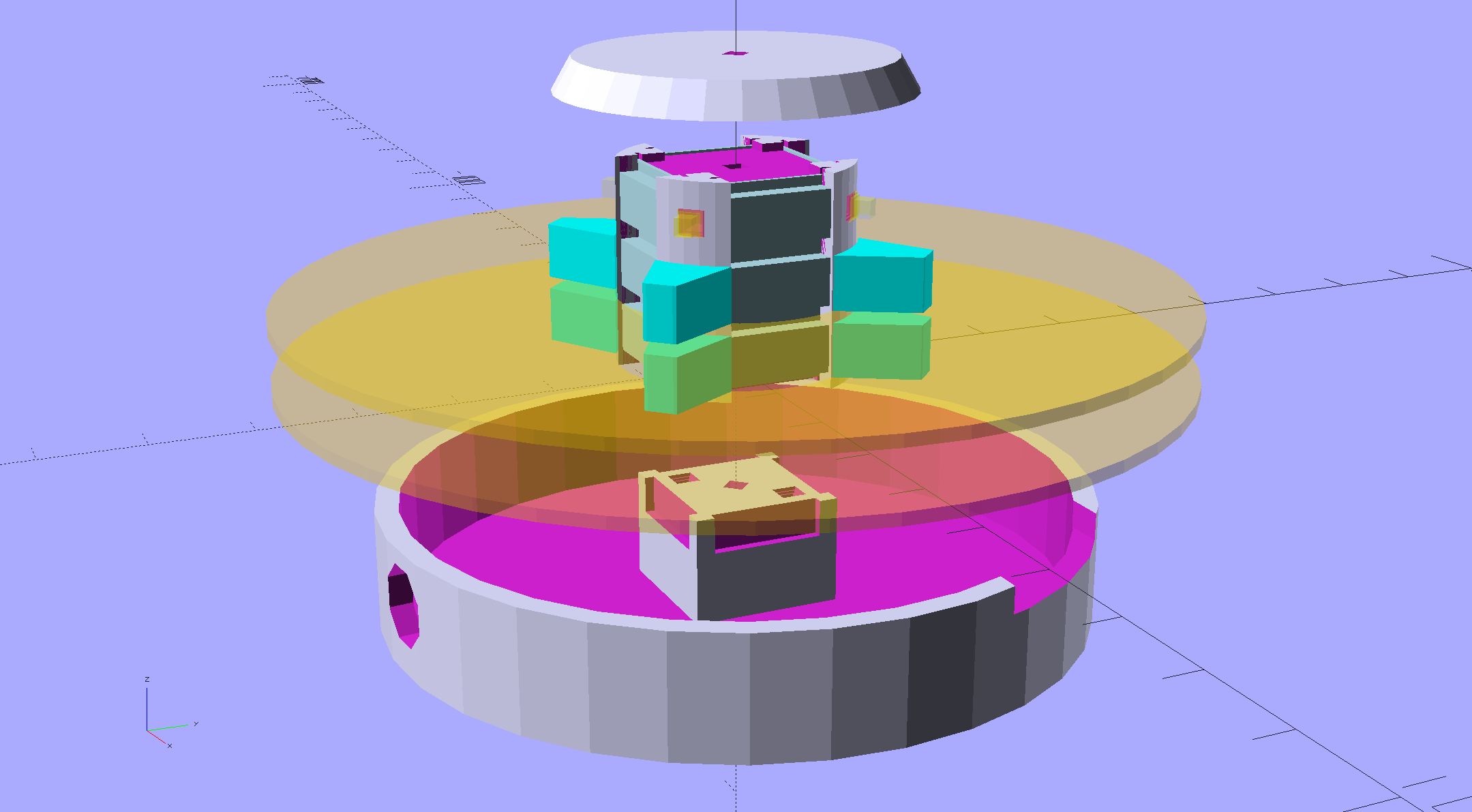
    An improved version of the 3D printed plastic bits going into the Hard Drive Platter Mood Light:

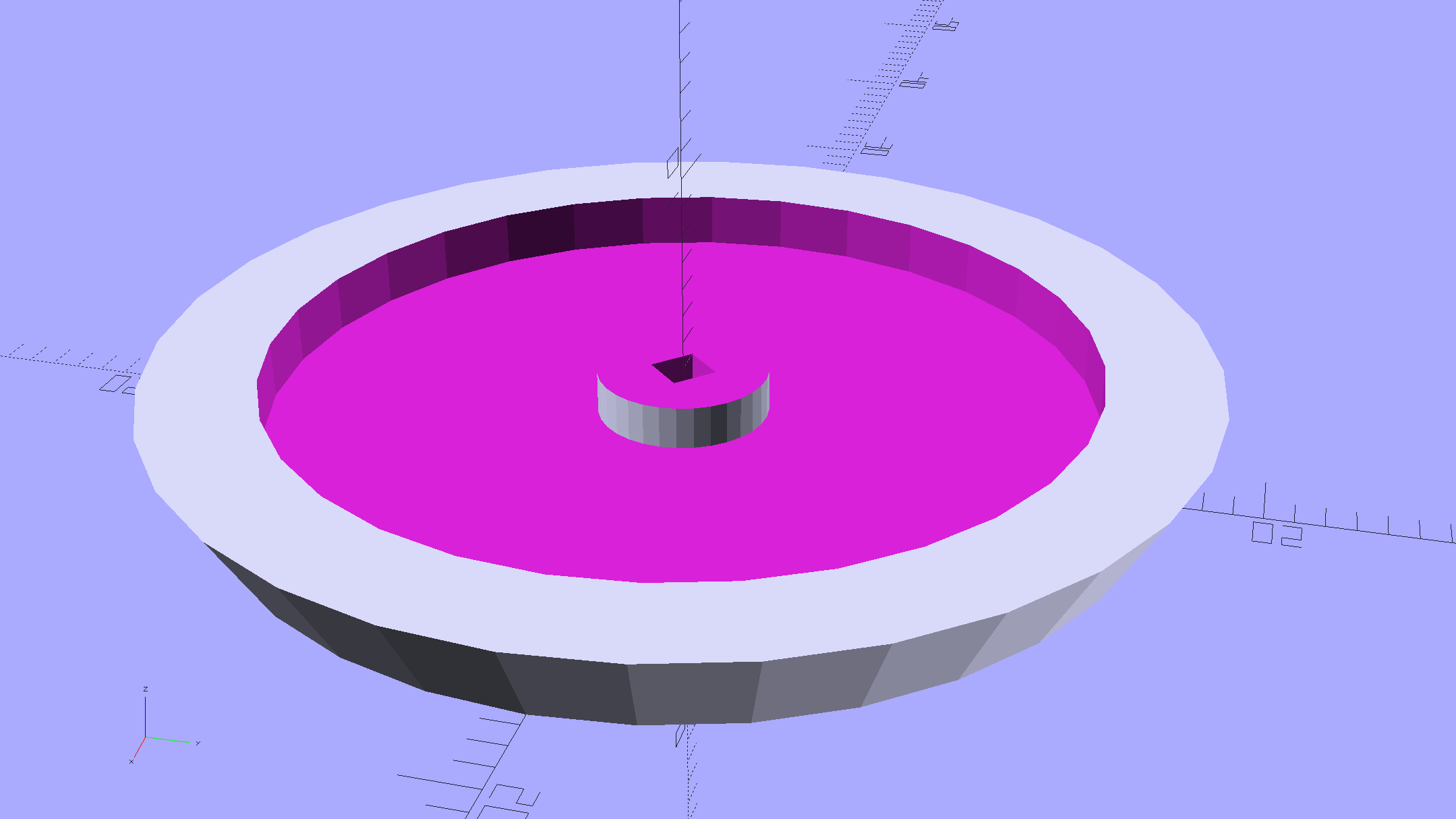
    Hard Drive Mood Light - improved - solid model - Show view
    Hard Drive Mood Light – improved – solid model – Show view

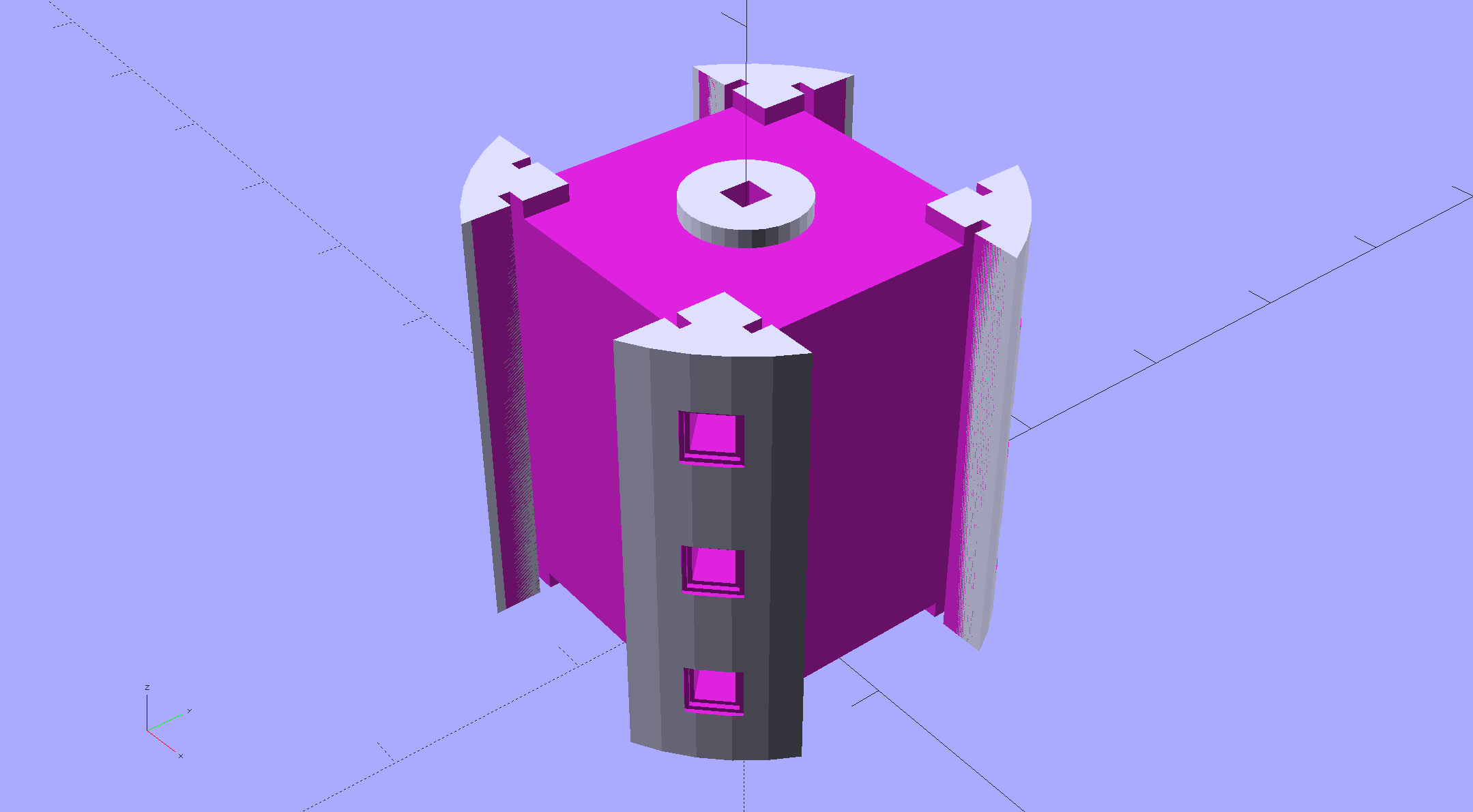
    The central pillar now has cutouts behind the Neopixel strips so you (well, I) can solder directly to the larger half-pads on the back, plus a boss on the top for better wire management:

    Hard Drive Mood Light - improved - Pillar - solid model
    Hard Drive Mood Light – improved – Pillar – solid model

    I’m not entirely satisfied with the little slots for the strip edges; the resolution limits of 3D printing call for larger openings, but there’s not much meat around those pins up the edge.

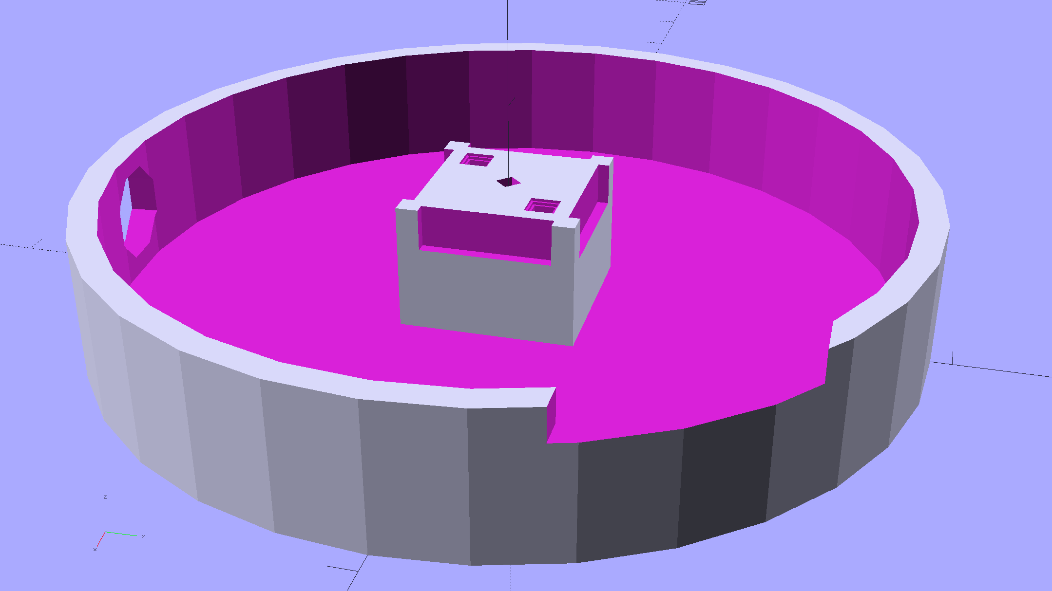
    The base becomes much larger to hold the Arduino Pro Mini and gains an optional slot to let the programming cable reach the outside:

    Hard Drive Mood Light - improved - Base - solid model
    Hard Drive Mood Light – improved – Base – solid model

    The cap has a boss matching the one atop the pillar:

    Hard Drive Mood Light - improved - Cap - solid model
    Hard Drive Mood Light – improved – Cap – solid model

    Both the cap & base have center features recessed by two thread thicknesses to let their rims apply a slight clamping force on the platters.

    Our Larval Engineer says it really needs an internal battery with maybe four hours of runtime, a charging base station (ideally with inductive power transfer), buttons (or, better, a tilt switch / accelerometer) for mode selection, and perhaps a microphone to synchronize lighting effects with music. To my horror, her co-op job seems to have exposed her to Marketeers…

    We do, however, agree that the Cap would look better in lathe-turned brass with a non-tarnish clearcoat.

    The OpenSCAD source code:

    // Hard Drive Platter Mood Light
    // Ed Nisley KE4ZNU November 2015
    
    Layout = "Spacers";					// Build Show Pixel LEDString Platters Pillar Spacers TopCap Base
    
    CablePort = true;
    
    ShowDisks = 2;						// number of disks in Show layout
    
    //- Extrusion parameters must match reality!
    
    ThreadThick = 0.25;
    ThreadWidth = 0.40;
    
    HoleWindage = 0.2;
    
    Protrusion = 0.1;			// make holes end cleanly
    
    inch = 25.4;
    
    function IntegerMultiple(Size,Unit) = Unit * ceil(Size / Unit);
    
    //----------------------
    // Dimensions
    
    ID = 0;
    OD = 1;
    LENGTH = 2;
    
    Platter = [25.0,95.0,1.27];						// hard drive platters - must match actual thickness!
    
    LEDStringCount = 3;								// number of LEDs on each strip
    LEDStripCount = 4;								// number of strips (verify locating pin holes & suchlike)
    
    WireSpace = 1.0;								// allowance for wiring along strip ends
    
    Pixel = [13.0, 1000 / 144, 0.6];				// smallest indivisible unit of LED strip
    PixelMargin = [1.0, 1.0, 2.0];					// LED and circuitry atop the strip
    
    BeamAngle = 120;								// LED viewing angle
    BeamShape = [
    	[0,0],
    	[Platter[OD]*cos(BeamAngle/2),-Platter[OD]*sin(BeamAngle/2)],
    	[Platter[OD]*cos(BeamAngle/2), Platter[OD]*sin(BeamAngle/2)]
    ];
    
    PillarSides = 12*4;
    
    PillarCore = Platter[ID] - 2*(Pixel[2] + PixelMargin[2] + 2.0);		// LED channel distance across pillar centerline
    PillarLength = LEDStringCount*Pixel[1] + Platter[LENGTH];
    echo(str("Pillar core size: ",PillarCore));
    echo(str("      ... length:"),PillarLength);
    
    PCB = [34.5,17.5,1.6];								// Arduino Pro Mini (or whatever) PCB size
    PCBClearTop = 5.0;
    PCBClearBot = 5.0;
    PCBHeight = PCB[2] + PCBClearBot + PCBClearTop;
    
    PCBRadius = sqrt(pow(Platter[ID]/2 + PCB[1],2) + pow(PCB[0]/2,2));
    echo(str("PCB Corner radius: ",PCBRadius));
    
    CoaxConn = [7.8,11.2,5.0];							// power connector 
    
    Cap = [Platter[ID] + 4.0,Platter[ID] + 4.0 + 10*2*ThreadWidth,2*WireSpace + 6*ThreadThick];		// cap over top of pillar
    CapSides = 8*4;
    
    BaseClearHeight = max(PCBHeight,CoaxConn[OD]);
    
    Base = [2.0 + 2*PCBRadius,2.0 + 2*PCBRadius + CoaxConn[LENGTH],BaseClearHeight + 6*ThreadThick];
    BaseSides = 8*4;
    
    Screw = [1.5,2.0,20.0];							// screws used to secure cap & pillar
    
    Spacer = [Platter[ID],(Platter[ID] + 2*8),(Pixel[1] - Platter[LENGTH])];
    echo(str("Spacer  OD: ",Spacer[OD]));
    echo(str(" ... thick:",Spacer[LENGTH]));
    
    LEDStripProfile = [
    	[0,0],
    	[Pixel[0]/2,0],
    	[Pixel[0]/2,Pixel[2]],
    	[(Pixel[0]/2 - PixelMargin[0]),Pixel[2]],
    	[(Pixel[0]/2 - PixelMargin[0]),(Pixel[2] + PixelMargin[2])],
    	[-(Pixel[0]/2 - PixelMargin[0]),(Pixel[2] + PixelMargin[2])],
    	[-(Pixel[0]/2 - PixelMargin[0]),Pixel[2]],
    	[-Pixel[0]/2,Pixel[2]],
    	[-Pixel[0]/2,0]
    ];
    
    //----------------------
    // Useful routines
    
    module PolyCyl(Dia,Height,ForceSides=0) {			// based on nophead's polyholes
    
      Sides = (ForceSides != 0) ? ForceSides : (ceil(Dia) + 2);
    
      FixDia = Dia / cos(180/Sides);
    
      cylinder(r=(FixDia + HoleWindage)/2,
    		h=Height,
    	$fn=Sides);
    }
    
    //- Locating pin hole with glue recess
    //  Default length is two pin diameters on each side of the split
    
    PinOD = 1.70;
    
    module LocatingPin(Dia=PinOD,Len=0.0) {
    	
    	PinLen = (Len != 0.0) ? Len : (4*Dia);
    	
    	translate([0,0,-ThreadThick])
    		PolyCyl((Dia + 2*ThreadWidth),2*ThreadThick,4);
    
    	translate([0,0,-2*ThreadThick])
    		PolyCyl((Dia + 1*ThreadWidth),4*ThreadThick,4);
    		
    	translate([0,0,-(PinLen/2 + ThreadThick)])
    		PolyCyl(Dia,(PinLen + 2*ThreadThick),4);
    
    }
    //----------------------
    // Pieces
    
    //-- LED strips
    
    module OnePixel() {
    	
    	render()
    		rotate([-90,0,0]) rotate(180)				// align result the way you'd expect from the dimensions
    			difference() {
    				linear_extrude(height=Pixel[1],convexity=3)
    					polygon(points=LEDStripProfile);
    				translate([-Pixel[0]/2,Pixel[2],-PixelMargin[0]])
    					cube([Pixel[0],2*PixelMargin[2],2*PixelMargin[0]]);
    				translate([-Pixel[0]/2,Pixel[2],Pixel[1]-PixelMargin[0]])
    					cube([Pixel[0],2*PixelMargin[2],2*PixelMargin[0]]);
    			}
    }
    
    module LEDString(n = LEDStringCount) {
    	
    	for (i=[0:n-1])
    		translate([0,i*Pixel[1]])
    //			resize([0,Pixel[1] + 2*Protrusion,0])
    				OnePixel();
    }
    
    //-- Stack of hard drive platters
    
    module Platters(n = LEDStringCount + 1) {
    	
    	color("gold",0.4)
    	for (i=[0:n-1]) {
    		translate([0,0,i*Pixel[1]])
    			difference() {
    				cylinder(d=Platter[OD],h=Platter[LENGTH],center=false,$fn=PillarSides);
    				cylinder(d=Platter[ID],h=3*Platter[LENGTH],center=true,$fn=PillarSides);
    			}
    	}
    }
    
    //-- Pillar holding the LED strips
    
    module Pillar() {
    	
    	difflen = PillarLength + 2*Protrusion;
    	
    //	render(convexity=5)
    	difference() {
    		linear_extrude(height=PillarLength,convexity=4)
    			difference() {
    				rotate(180/(12*4))
    					circle(d=Platter[ID] - 1*ThreadWidth,$fn=PillarSides);
    				
    				for (i=[0:LEDStripCount-1]) 					// clearance for LED beamwidth, may not actually cut surface
    					rotate(i*360/LEDStripCount)
    						translate([PillarCore/2,0,0])
    							polygon(points=BeamShape);
    							
    				for (i=[0:LEDStripCount-1])						// LED front clearance
    					rotate(i*360/LEDStripCount)
    						translate([(PillarCore/2 + Pixel[2]),(Pixel[0] - 2*PixelMargin[0])/2])
    							rotate(-90)
    								square([Pixel[0] - 2*PixelMargin[0],Platter[ID]]);
    
    			}
    			
    		for (i=[0:LEDStripCount-1])								// LED strip slots
    			rotate(i*360/LEDStripCount)
    				translate([PillarCore/2,0,-Protrusion])
    					linear_extrude(height=difflen,convexity=2)
    						rotate(-90)
    							polygon(points=LEDStripProfile);
    		
    		difference() {											// wiring recess on top surface, minus boss
    			for (i=[0,90])
    				rotate(i)
    					translate([0,0,(PillarLength - (WireSpace/2 - Protrusion))])
    						cube([(PillarCore + 2*Protrusion),Pixel[0] - 2*PixelMargin[0],WireSpace],center=true);
    			cylinder(d=3*Screw[OD],h=PillarLength + Protrusion,$fn=CapSides);
    		}
    							
    		for (i=[0:LEDStripCount-1])								// wiring recess on bottom surface
    			rotate(i*90)
    				translate([PillarCore/2 - (WireSpace - Protrusion)/2,0,WireSpace/2 - Protrusion])
    					cube([WireSpace + Protrusion,Pixel[0] - 2*PixelMargin[0],WireSpace],center=true);
    							
    		for (j=[0:LEDStringCount-1])							// platter spacer alignment pins
    			for (i=[0:LEDStripCount-1])
    				rotate(i*360/LEDStripCount + 180/LEDStripCount)
    					translate([(Platter[ID] - 1*ThreadWidth)/2,0,(j*Pixel[1] + Pixel[1]/2 + Platter[LENGTH]/2)])
    						rotate([0,90,0])
    							rotate(45)
    								LocatingPin();
    								
    		translate([0,0,-Protrusion])							// central screw hole
    			rotate(180/4)
    				PolyCyl(Screw[ID],difflen,4);
    		
    		if (false)
    		for (i=[-1,1])											// vertical wire channels
    			rotate(i*360/LEDStripCount + 180/LEDStripCount)
    				translate([PillarCore/2 - 2.0,0,-Protrusion])
    					PolyCyl(2.0,difflen,4);
    					
    		for (i=[-1,1])											// locating pins
    			rotate(i*360/LEDStripCount - 180/LEDStripCount)
    				translate([PillarCore/2 - 2.0,0,0])
    					LocatingPin();
    	}
    }
    
    //-- Spacers to separate platters
    
    module Spacers() {
    
    	difference() {
    		linear_extrude(height=Spacer[LENGTH],convexity=4)
    			difference() {
    				rotate(180/PillarSides)
    					circle(d=Spacer[OD],$fn=PillarSides);
    				
    				for (i=[0:LEDStripCount-1]) 					// clearance for LED beamwidth, may not actually cut surface
    					rotate(i*360/LEDStripCount)
    						translate([PillarCore/2,0,0])
    							polygon(points=BeamShape);
    							
    				for (i=[0:LEDStripCount-1])						// LED front clearance
    					rotate(i*360/LEDStripCount)
    						translate([(PillarCore/2 + Pixel[2]),(Pixel[0] - 2*PixelMargin[0])/2])
    							rotate(-90)
    								square([Pixel[0] - 2*PixelMargin[0],Platter[ID]]);
    
    							
    				rotate(180/PillarSides)
    					circle(d=Spacer[ID],$fn=PillarSides);		// central pillar fits in the hole
    			}
    			
    		for (i=[0:LEDStripCount-1])
    			rotate(i*360/LEDStripCount + 180/LEDStripCount)
    				translate([Platter[ID]/2,0,(Pixel[1] - Platter[LENGTH])/2])
    					rotate([0,90,0])
    						rotate(45)
    							LocatingPin();
    
    	}
    }
    
    //-- Cap over top of pillar
    
    module TopCap() {
    	
    	difference() {
    		cylinder(d1=(Cap[OD] + Cap[ID])/2,d2=Cap[OD],h=Cap[LENGTH],$fn=CapSides);		// outer lid
    		
    		translate([0,0,-Protrusion])
    			PolyCyl(Screw[ID],Cap[LENGTH] + WireSpace + Protrusion,4);					// screw hole
    		
    		translate([0,0,Cap[LENGTH] - 2*WireSpace])
    			difference() {
    				cylinder(d=Cap[ID],h=2*Cap[LENGTH],$fn=CapSides);						// cutout
    				cylinder(d=3*Screw[OD],h=Cap[LENGTH],$fn=CapSides);						// boss
    			}
    		
    		translate([0,0,Cap[LENGTH] - 2*ThreadThick])
    			cylinder(d=Cap[ID]/2,h=2*ThreadThick + Protrusion,$fn=CapSides);			// recess boss
    	}
    }
    
    //-- Base below pillar
    
    module Base() {
    	
    	SideWidth = 0.5*Base[OD]*sin(180/BaseSides);						// close enough
    	
    	difference() {
    		union() {
    			difference() {
    				cylinder(d=Base[OD],h=Base[LENGTH],$fn=BaseSides);			// outer base
    
    				translate([0,0,6*ThreadThick])								// main cutout
    					cylinder(d=Base[ID],h=Base[LENGTH],$fn=BaseSides);
    					
    				rotate(180/BaseSides)
    					translate([0,0,Base[LENGTH] - BaseClearHeight/2]) 					// power connector hole
    						rotate([90,0,0]) rotate(180/8)
    							PolyCyl(CoaxConn[ID],Base[OD],8);
    			}
    			
    			translate([0,0,Base[LENGTH]/2])									// recess pillar support below rim
    				cube([PillarCore,PillarCore,Base[LENGTH] - 2*ThreadThick],center=true);
    		}
    
    		for (i=[0:LEDStripCount-1])											// wiring recesses
    			rotate(i*90)
    				translate([PillarCore/2 - (WireSpace - Protrusion)/2,0,Base[LENGTH] - 4*WireSpace/2])
    					cube([WireSpace + Protrusion,PillarCore - 4*WireSpace,4*WireSpace],center=true);
    		
    		translate([0,0,-Protrusion])
    			PolyCyl(Screw[ID],2*Base[LENGTH],4);						// screw hole
    			
    		translate([0,0,-Protrusion])									// screw head recess
    			rotate(180/8)
    				PolyCyl(8.5,Base[LENGTH] - 3.0 + Protrusion,8);
    			
    		for (i=[-1,1])													// locating pins
    			rotate(i*360/LEDStripCount - 180/LEDStripCount)
    				translate([PillarCore/2 - 2.0,0,Base[LENGTH] - ThreadThick])
    					LocatingPin();
    					
    		if (CablePort)
    			translate([0,Platter[ID]/2 + PCB[1],Base[LENGTH] - 3.0 + Protrusion])
    				rotate(-90)
    					cube([PCB[1],Base[OD],3.0]);
    
    	}
    		
    }
    
    //----------------------
    // Build it
    
    if (Layout == "Pixel")
    	OnePixel();
    	
    if (Layout == "LEDString")
    	LEDString(LEDStringCount);
    	
    if (Layout == "Platters")
    	Platters(LEDStringCount + 1);
    	
    if (Layout == "Pillar")
    	Pillar(LEDStringCount);
    	
    if (Layout == "TopCap")
    	TopCap();
    		
    if (Layout == "Base")
    	Base();
    
    if (Layout == "Spacers")
    	Spacers();
    	
    if (Layout == "Show") {
    	Pillar();
    
    	for (i=[0:LEDStripCount-1])											// LED strips
    		rotate(i*360/LEDStripCount)
    			translate([PillarCore/2,0,Platter[LENGTH]/2])
    				rotate([90,0,90])
    					color("lightblue") LEDString();
    	if (true)	
    	for (j=[0:max(1,ShowDisks - 2)])									// spacers
    		translate([0,0,(j*Pixel[1] + Platter[LENGTH])])
    			color("cyan") Spacers();
    							
    	for (j=[0:max(2,ShowDisks - 2)])										// spacer alignment pins
    		for (i=[0:LEDStripCount-1])
    			rotate(i*360/LEDStripCount + 180/LEDStripCount)
    				translate([(Platter[ID] - 1*ThreadWidth)/2,0,(j*Pixel[1] + Pixel[1]/2 + Platter[LENGTH]/2)])
    					rotate([0,90,0])
    						rotate(45)
    							 color("Yellow",0.25) LocatingPin(Len=4);
    	translate([0,0,PillarLength + 3*Cap[LENGTH]])
    		rotate([180,0,0])
    			TopCap();
    	
    	translate([0,0,-2*Base[LENGTH]])
    		Base();
    		
    	if (ShowDisks > 0)	
    		Platters(ShowDisks);
    	
    }
    
    // Ad-hoc build layout
    
    if (Layout == "Build") {
    	if (true)
    		Pillar();
    	
    	if (true)
    		translate([0,(Platter[ID] + Cap[OD])/2,0])
    			TopCap();
    			
    	if (true)
    		translate([0,-(Platter[ID] + Base[OD])/2,0])
    			Base();
    				
    	Ybase = Spacer[OD] * (LEDStringCount%2 ? (LEDStringCount - 1) : (LEDStringCount - 2)) / 4;
    	if (true)
    		for (i=[0:LEDStringCount])										// build one extra set of spacers!
    			translate([(i%2 ? 1 : -1)*(Spacer[OD] + Base[OD])/2,		// alternate X sides to shrink Y space
    					(i%2 ? i-1 : i)*Spacer[OD]/2 - Ybase,				// same Y for even-odd pairs in X
    					0])
    				Spacers();
    }
    
  • Hard Drive Platter Thicknesses

    It should come as no surprise that hard drive platters have different thicknesses:

    Hard Drive Platter Thickness
    Hard Drive Platter Thickness

    The thicker ones measure 1.25 mm, which is near enough to 50 mils to suggest they date back to the Good Old Days. The three thinner ones in the middle are 0.77 mm = 30 mil and could be slightly younger than dirt. There’s more where these came from and I expect more variation on the theme.

    The beveled edges make the platters look thinner than they really are; they’re firmly clamped together with no space between them.

    As nearly as I can tell, the IBM 350 Disk Storage Unit on the IBM 350 RAMAC had platters about 25 mil thick. Those were two feet in diameter, so they definitely don’t make ’em like they used to!

    The thickness wouldn’t matter, except that the OpenSCAD program producing the hub & spacer tabs for the Mood Lights needs to know.

  • Kenmore Vacuum Cleaner Tool Adapters

    After donating the never–sufficiently-to-be-damned Samsung vacuum cleaner (and all its remaining bags & doodads) to a nonprofit’s tag sale, we picked up a Sears Kenmore Progressive vacuum cleaner that seemed to be the least awful of the current offerings. Unlike all previous vacuum cleaners, its tools & doodads have complex plastic fittings with latches and keyways and all manner of gimcrackery. The designers seem to have hands and legs of far-above-average size, but that’s another rant.

    All this came to a head when I attempted to vacuum the fuzz out of the refrigerator’s evaporator coils, because the long snout that reaches the back of the refrigerator doesn’t fit the aperture in the giant handle.

    Well, at least I can fix that…

    The first step involved modeling the plastic fitting that snaps into the handle:

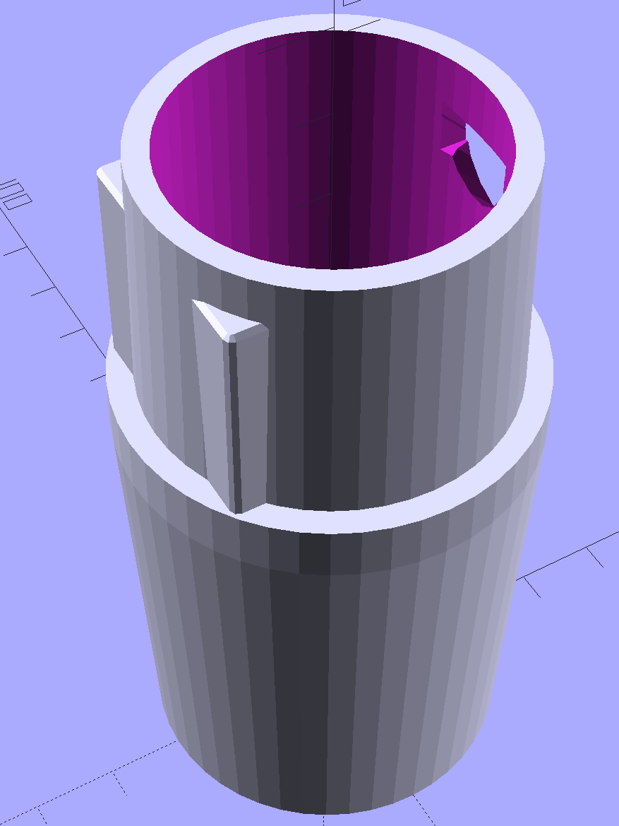
    Kenmore Male Fitting - Solid model
    Kenmore Male Fitting – Solid model

    The latch on the handle snaps into an opening that took some tinkering to reproduce. Stand back, I’m going to use trigonometry:

                translate([0,-11.5/2,23.0 - 5.0])                                    // latch opening
                    cube(Latch);
                    
                translate([OEMTube[ID1]/2 + EntryHeight/tan(90-EntryAngle),0,0])    // latch ramp
                    translate([(Latch[1]/cos(180/EntrySides))*cos(EntryAngle)/2,0,(Latch[1]/cos(180/EntrySides))*sin(EntryAngle)/2])
                        rotate([0,-EntryAngle,0])
                            intersection() {
                                rotate(180/EntrySides)
                                    PolyCyl(Latch[1],Latch[0],EntrySides);
                                translate([-(2*Latch[0])/2,0,-Protrusion])
                                    cube(2*Latch[0],center=true);
                            }
    

    Which spits out two suitable shapes with the proper positions and alignments:

    Kenmore Male Fitting - Latch detail - Solid model
    Kenmore Male Fitting – Latch detail – Solid model

    The magic wand for the refrigerator originally slid into the Samsung’s metal pipe, so I put a slightly tapered cylinder inside a somewhat more tapered exterior (which seems chunky enough to withstand my flailing around under the refrigerator), then topped it off with the male fitting:

    Refrigerator Coil Wand Adapter
    Refrigerator Coil Wand Adapter

    The Kenmore crevice tool snaps under the gargantuan plastic handle, which limits it to being 6.5 inches long, totally unable to reach into any of the nontrivial crevices around here, and in the way when it’s not being used. Some rummaging turned up a longer crevice tool from the Electrolux That Came With The House™, an old-school tool that slipped over its pipe. Modeling a straight cylinder inside a tapered cylinder that fits the tool didn’t take long:

    Crevice Tool Adapter
    Crevice Tool Adapter

    Flushed with success, I found a smaller floor brush than the new Kenmore, with dimensions similar to the Electrolux snout, so another module appeared:

    Floor Brush Adapter
    Floor Brush Adapter

    All of them build with the latch end upward to avoid needing support structure, with a 5 mm brim for good platform adhesion:

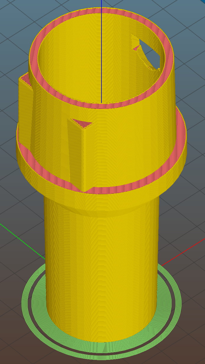
    Floor Brush Adapter - Slic3r preview
    Floor Brush Adapter – Slic3r preview

    I printed them during the PDS Mini Maker Faire as examples of Useful Things You Can Do With a 3D Printer:

    Kenmore Vacuum Cleaner - Tool Adapters
    Kenmore Vacuum Cleaner – Tool Adapters

    As I pointed out to nearly everybody, the Big Lie about 3D printing is that you’ll just download somebody else’s model to solve your problem. In general, that won’t work, because nobody else has your problem; if you can’t do solid modeling, there’s no point in you having a 3D printer. There’s also no point in going to Kinko’s to get a standardized 3D printed doodad, because you can just order a better-looking injection-molded part directly from Sears (or an aftermarket source) and be done with it.

    I loves me some good OpenSCAD action on my Makergear M2, though…

    The OpenSCAD source code:

    // Kenmore vacuum cleaner nozzle adapters
    // Ed Nisley KE4ZNU November 2015
    
    // Layout options
    
    Layout = "CreviceTool";        // MaleFitting CoilWand FloorBrush CreviceTool
    
    //- Extrusion parameters must match reality!
    //  Print with +1 shells and 3 solid layers
    
    ThreadThick = 0.25;
    ThreadWidth = 0.40;
    
    HoleWindage = 0.2;
    
    function IntegerMultiple(Size,Unit) = Unit * ceil(Size / Unit);
    
    Protrusion = 0.1;           // make holes end cleanly
    
    //----------------------
    // Dimensions
    
    ID1 = 0;                                                // for tapered tubes
    ID2 = 1;
    OD1 = 2;
    OD2 = 3;
    LENGTH = 4;
    
    OEMTube = [35.0,35.0,41.7,40.5,30.0];                    // main fitting tube
    EndStop = [OEMTube[ID1],OEMTube[ID2],47.5,47.5,6.5];    // flange at end of main tube
    
    FittingOAL = OEMTube[LENGTH] + EndStop[LENGTH];
    
    $fn = 12*4;
    
    //----------------------
    // Useful routines
    
    module PolyCyl(Dia,Height,ForceSides=0) {           // based on nophead's polyholes
    
    Sides = (ForceSides != 0) ? ForceSides : (ceil(Dia) + 2);
    
    FixDia = Dia / cos(180/Sides);
    
    cylinder(r=(FixDia + HoleWindage)/2,
             h=Height,
             $fn=Sides);
    }
    
    
    //-------------------
    // Male fitting on end of Kenmore tools
    // This slides into the end of the handle or wand and latches firmly in place
    
    module MaleFitting() {
        
    Latch = [40,11.5,5.0];                    // rectangle latch opening
    EntryAngle = 45;                        // latch entry ramp
    EntrySides = 16;
    EntryHeight = 15.0;                        // lower edge on *inside* of fitting
    
    KeyRadius = 1.0;
            
        translate([0,0,6.5])
            difference() {
                union() {
                    cylinder(d1=OEMTube[OD1],d2=OEMTube[OD2],h=OEMTube[LENGTH]);            // main tube
                    
                    hull()                                                                    // insertion guide
                        for (i=[-(6.0/2 - KeyRadius),(6.0/2 - KeyRadius)], 
                            j=[-(28.0/2 - KeyRadius),(28.0/2 - KeyRadius)], 
                            k=[-(26.0/2 - KeyRadius),(26.0/2 - KeyRadius)])
                            translate([(i - (OEMTube[ID1]/2 + OEMTube[OD1]/2)/2 + 6.0/2),j,(k + 26.0/2 - 1.0)])
                                sphere(r=KeyRadius,$fn=8);
                    
                    translate([0,0,-EndStop[LENGTH]])                                // wand tube butts against this
                        cylinder(d=EndStop[OD1],h=EndStop[LENGTH] + Protrusion);
                }
                
                translate([0,0,-OEMTube[LENGTH]])                                    // main bore
                    cylinder(d=OEMTube[ID1],h=2*OEMTube[LENGTH] + 2*Protrusion);
                    
                translate([0,-11.5/2,23.0 - 5.0])                                    // latch opening
                    cube(Latch);
                    
                translate([OEMTube[ID1]/2 + EntryHeight/tan(90-EntryAngle),0,0])    // latch ramp
                    translate([(Latch[1]/cos(180/EntrySides))*cos(EntryAngle)/2,0,(Latch[1]/cos(180/EntrySides))*sin(EntryAngle)/2])
                        rotate([0,-EntryAngle,0])
                            intersection() {
                                rotate(180/EntrySides)
                                    PolyCyl(Latch[1],Latch[0],EntrySides);
                                translate([-(2*Latch[0])/2,0,-Protrusion])
                                    cube(2*Latch[0],center=true);
                            }
            }
    }
    
    //-------------------
    // Refrigerator evaporator coil wand
    
    module CoilWand() {
        
        union() {
            translate([0,0,50.0])
                rotate([180,0,0])
                    difference() {
                        cylinder(d1=EndStop[OD1],d2=42.0,h=50.0);
                        translate([0,0,-Protrusion])
                            cylinder(d1=35.0,d2=35.8,h=100);
                    }
            translate([0,0,50.0 - Protrusion])
                MaleFitting();
        }
    }
    
    
    //-------------------
    // Refrigerator evaporator coil wand
    
    module FloorBrush() {
        
        union() {
            translate([0,0,60.0])
                rotate([180,0,0])
                    difference() {
                        union() {
                            cylinder(d1=EndStop[OD1],d2=32.4,h=10.0);
                            translate([0,0,10.0 - Protrusion])
                                cylinder(d1=32.4,d2=30.7,h=50.0 + Protrusion);
                        }
                        translate([0,0,-Protrusion])
                            cylinder(d1=28.0,d2=24.0,h=100);
                    }
            translate([0,0,60.0 - Protrusion])
                MaleFitting();
        }
    }
    
    
    //-------------------
    // Crevice tool
    
    module CreviceTool() {
        
        union() {
            translate([0,0,60.0])
                rotate([180,0,0])
                    difference() {
                        union() {
                            cylinder(d1=EndStop[OD1],d2=32.0,h=10.0);
                            translate([0,0,10.0 - Protrusion])
                                cylinder(d1=32.0,d2=30.4,h=50.0 + Protrusion);
                        }
                        translate([0,0,-Protrusion])
                            cylinder(d1=28.0,d2=24.0,h=100);
                    }
            translate([0,0,60.0 - Protrusion])
                MaleFitting();
        }
    }


    //----------------------
    // Build it!
    
    if (Layout == "MaleFitting")
        MaleFitting();
    
    if (Layout == "CoilWand")
        CoilWand();
    
    if (Layout == "FloorBrush")
        FloorBrush();
    
    if (Layout == "CreviceTool")
        CreviceTool();