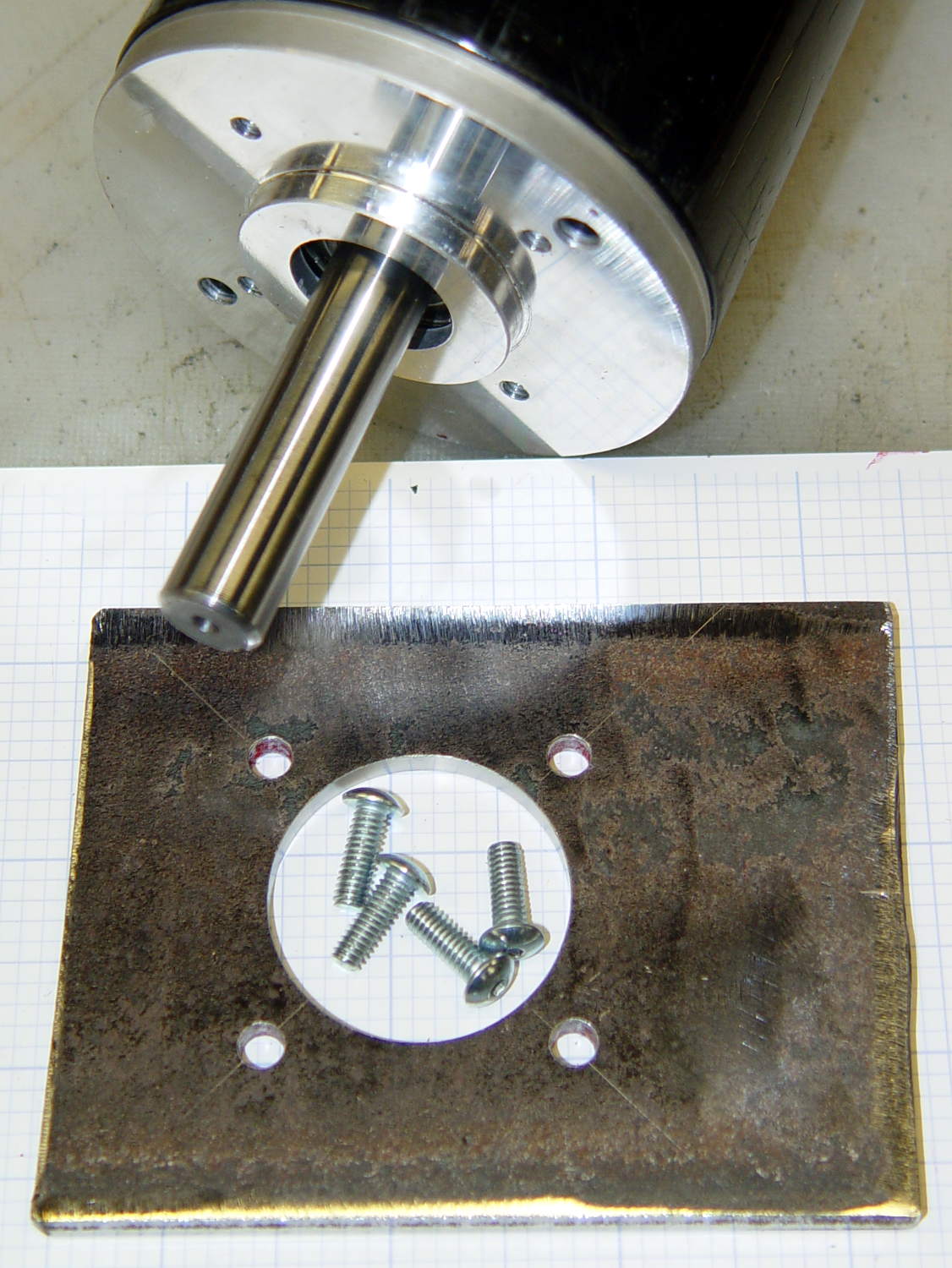
The Squidwrench Power Wheels Racer needed a mounting bracket for its DC motor, so Matt handed me a precut steel slab and some drawings. I did a manual layout to get a feel for the sizes:
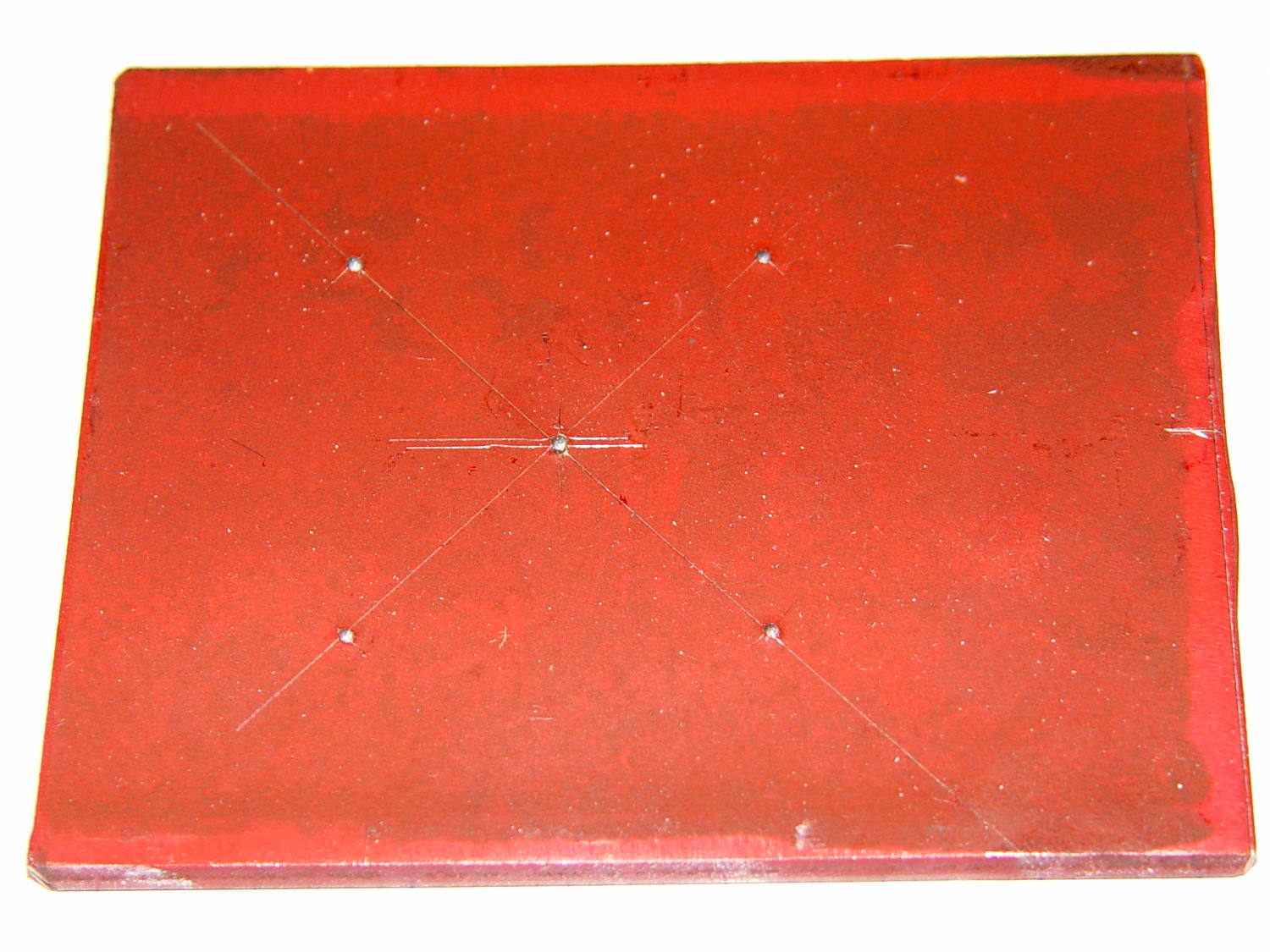
Yes, it’s slightly rhomboid & irregular on the sides; it’ll be welded to a U-channel. The front edge is the straightest and I scribed a perpendicular datum line over on the right, from which to measure the motor center point.
But then, realizing I’d have to mill the central hole anyway, I did what I should have done from the beginning and lined it up on the Sherline:
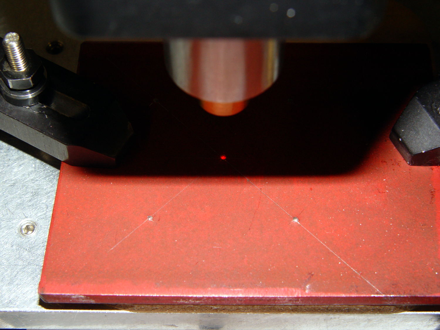
With the part zeroed at the center, everything has polar coordinates. The bolt holes are #10 on a 50 mm BCD, which is G0 @25^[45+90*i]. Rather than writing & debugging a program, I did it all by feeding manual instructions into the interpreter; the i gets typed as 0, 1, 2, and 3 by clicking on a previous command, backspacing, and retyping, which is both faster and easier than it sounds. The holes are drill cycles: G81 Z-7 R1 F30
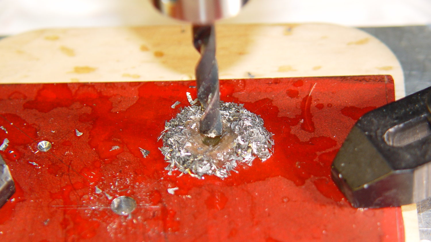
This being steel on a Sherline, the rule of thumb that says you can drill at 100x the drill diameter (in inch/min or mm/min, as appropriate) at 3000 RPM gets derated by at least factor of 10. I settled on 30 mm/min for a #10 drill (0.194 inch = 4.9 mm → 500 mm/min = hogwash) after trying the first hole at 50 mm/min:
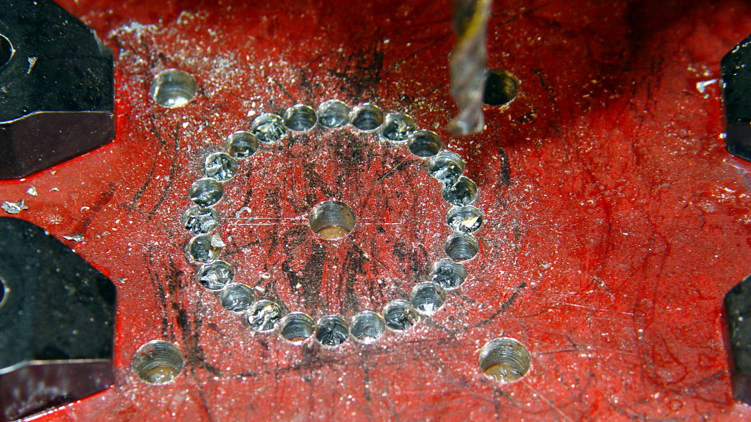
The least horrible way to cut out the hole for the motor mounting boss involved chain drilling to excavate the most steel with the least effort. These center drill points are at G0 @14 ^[15*i] with i in [0..23]:
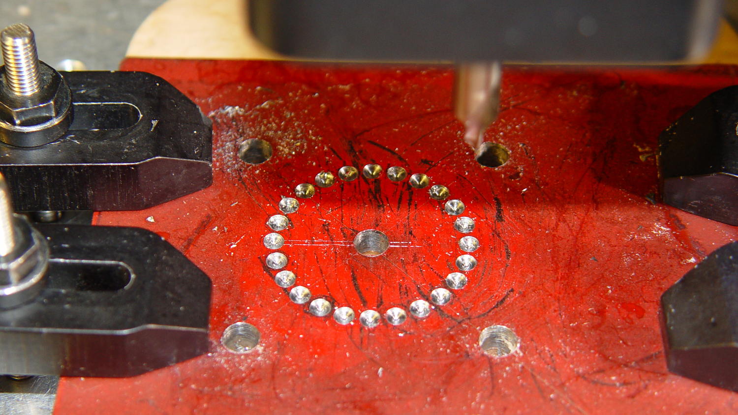
I drilled every even hole #27, then every odd hole #28, both at 50 mm/min, to get a thin web:
Then helix-mill downward with a 1/8 inch end mill at 1 mm per pass:
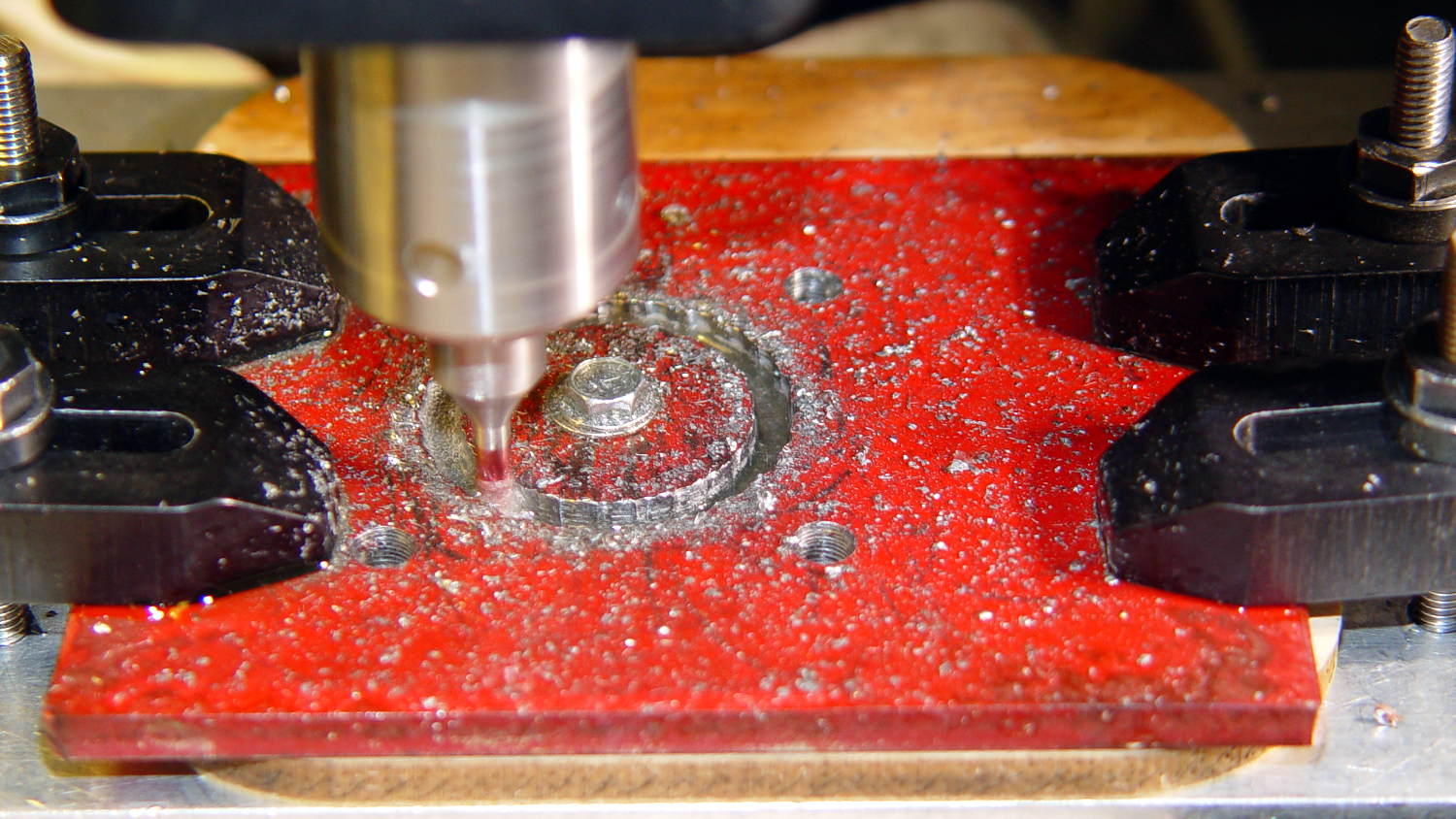
That started at 14 mm from the origin to match the hole circle: G3 I-14 F100 Z-1
Then I switched to a 3/8 inch = 9.5 mm end mill to bring the hole up to size, ending with G3 I-12.75 F300
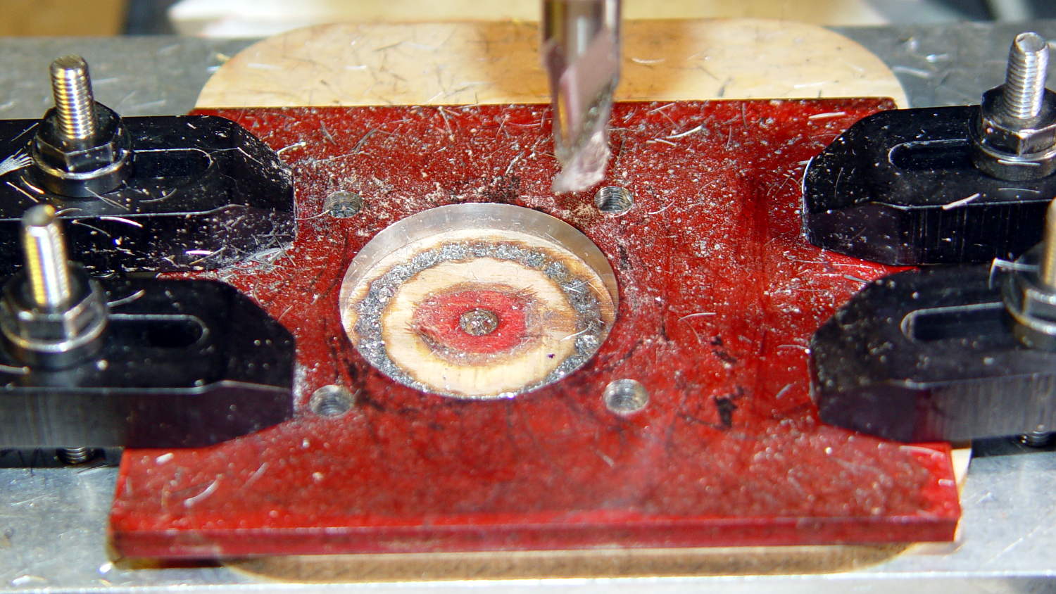
A trial fit showed the hole was slightly off-round, probably due to a few mils of backlash in both axes, and slightly too small, because that’s how I wanted it. Flipped back-to-front, reclamped, recentered, ran the cutter around at 12.75 mm to clear the ovalness, then crept out to 12.8 mm, and it was all good:
That’s an easy fit with maybe 0.1 mm = 4 mil radial play around the boss. Better than that, I cannot do.
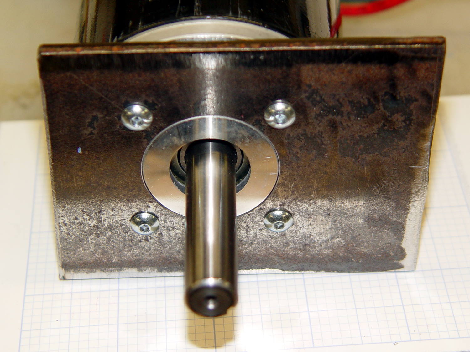
Lacquer thinner stripped the layout dye and it’s ready for welding:
Reminders for next time…
The drill feed on a rigid machine with plenty of spindle power is 100 x (drill dia) @ 3000 RPM. On the Sherline, in steel, 10 x dia is optimistic. Aluminum feeds run higher, but don’t get stupid.
Re-centering to the accuracy required for this job is a matter of noting the coordinates where the cutter kisses the perimeter across a diameter along each axis, adding the coordinates, dividing by two, moving to that position, and zeroing the origin. Do that in X, Y, X, and Y and it’s good enough. You could automate that with a touch probe, of course. Hand-turning the spindle with the cutter in place to feel it kiss the workpiece is fine, but use the same cutting edge on both sides of the diameter.
Figure the chain drill diameter thusly:
- Pick a reasonable drill diameter; #10 is about as large as you want on a Sherline
- Drill circle dia = final milled hole diameter – drill dia – 2 mm, round down to lower integer
- # holes = π x DCD / drill dia, rounded down to lower integer
- Hole angle = 360 / # holes
- Hole radius = DCD / 2
Wisely is it written that a man with a CNC milling machine has many friends.

Comments
12 responses to “DC Motor Mounting Plate”
“Better than that, I cannot do”
Really? Boring head?
That’d probably do better, if only I had one. A real machinist would center it on the rotary table, drill the mounting holes, put a starter hole in the middle, then spin it around an end mill.
I almost abused the flycutter’s carbide insert on the side of the hole, but I came to my senses..
Never got into chain-drilling, but years ago I got boring heads for the mill-drill and a small one from Sherline. (The new ones look easier to use…) The sufficiently motivated (or deranged) do this on a lathe, but I prefer to keep the large 4-jaw chuck on the shelf. At 8″ and 50 pounds, I use it when it’s absolutely necessary. I got a 5″ from a club member that does most of my 4-jaw stuff.
The power wheels racing series looks fun. It reminds me of the 24 hours of Lemons cruftwagon racing series with a similar amount of lunacy. (Cheaper, though–Lemons need a roll cage and good tires, since the speeds can get medium high.)
Aye! The one I have is but 36 pounds and entirely too heavy for casual swapping. Haven’t used it in quite a while, which is fine with me!
They’ve been keeping me away from the Power Wheels project (which is coming along wonderfully), because I’m the guy who can explain why whatever it is they want to do won’t work that way: engineering buzzkill has no place there… [grin]
I’ve had a similar problem (being a buzzkill) but my project manager cured me. She came to me one day and said: Hey I get it, you see problems with everything we do but please stop bitching about it and pitch in a better solution. Think up solutions, not problems.
In hindsight, that’s pretty obvious advice, but back in the day it was a real eye opener for me :)
Father Vaughn taught that you should never bring your manager a problem. Instead, bring a problem and your proposed solution; most likely, you’ll get to do it your way.
Sometimes, for what seem well and good reasons, a problem’s definition excludes all the feasible solutions, whereupon it’s tough to remain upbeat.
“Wisely is it written that a man with a CNC milling machine has many friends.”
Get yourself a pickup truck and you will suddenly have many more friends!
(So says One Who Knows!)
Did you know you can drill a full circle of holes in polar mode with something like: G90 G0 Y0 X25 (set up desired radius; could also use @25 ^0) and then something like G91 G81 R1 Z-8 ^15 L24 (drill 24 holes incrementing 15 degrees before each hole)?
Aye, but every time I read “the output is not what you might expect” in the doc on polar coordinates, I think “Yes, that would be me…” [grin]
I had one Golden Sheet of Steel and couldn’t afford a mistake that’s obvious in retrospect. Setting up each position “manually” before the drill cycle limited the potential damage to a single hole, at the cost of some mouse-clicky typey-type action.
If I knew the speeds-and-feeds would poke every hole correctly and nothing would go wrong, doing the whole ring in one statement makes perfect sense. But I’d have to poke a few test holes, run some air cuts to wring out the typos, and hover over the panic stop button in case the Sherline’s poor Z-axis stalled in mid-hole. Net, it’d take about the same amount of time and use up even more of my adrenaline supply.
Another decade or two should give me, oh, 10% of the experience you folks take for granted… [sigh]
“This being steel on a Sherline, the rule of thumb that says you can drill at 100x the drill diameter (in inch/min or mm/min, as appropriate) at 3000 RPM gets derated by at least factor of 10.”
I’ve been noodling on this a bit, and it seems counter intuitive to me…. Can you explain it a bit more? So the larger the diameter, the faster the feed rate? I always thought (and tried to do) that you calculate/guestimate the RPM based on surface feet per minute, then the feed rate to get the chip load you want “about 0.001 to 0.003 per tooth, per rev”.
Thanks,
Steve
The reason it works is you’re holding the RPM constant. Because the SFM goes up with the diameter, the feed must increase with the diameter to maintain the same chip load. Apparently, 3000 RPM produces a “good enough” SFM over the range of “useful diameters” for “most materials”.
The gotcha: the spindle horsepower also goes up (I think as the square of the diameter) and the Sherline runs out of steam in short order. AFAICT, though, the Sherline’s Z axis motor limits the feed, because it can’t produce enough downforce to ram the drill into the metal as fast as the spindle needs.
The place I found this (which is long gone, alas) was a story about a shop newbie who applied the rule of thumb to feed a 1 inch drill at 100 inch/minute through thick steel plate. The shop foreman heard the machine making a very loud whoomp with every hole, but it drilled perfectly. Sprayed the area with blue-hot shrapnel, of course…
[…] part of the power train autopsy, Matt pointed me at the specs for the AmpFlow E30-400 motor they built into the chassis. The Performance Chart (mooched from AmpFlow to forestall link rot) provides useful […]