Ed Nisley's Blog: Shop notes, electronics, firmware, machinery, 3D printing, laser cuttery, and curiosities. Contents: 100% human thinking, 0% AI slop.
Category: Software
General-purpose computers doing something specific
While reducing the clutter atop the Electronics Workbench, I ran off four more probe flange reinforcements, just so I’m ready for the next crunch:
HP scope probe flange disks
They’re almost identical to the previous version, although I tweaked the taper to end slightly inside the cylindrical cup, thereby eliminating the coincident faces and leaving a minute rim that doesn’t matter:
HP Scope Probe Flange Repair – bottom
Given that I’ve had the ‘scope for nigh onto two decades and have only broken one probe flange, I think four reinforcements will be a lifetime supply: with any luck, the scope will blow a capacitor before I do.
The OpenSCAD source code:
// Tek Scope Probe Flange
// Ed Nisley KE4ZNU November 2013

//- Extrusion parameters must match reality!
//  Print with 2 shells and 3 solid layers

ThreadThick = 0.20;
ThreadWidth = 0.40;

HoleWindage = 0.2;

Protrusion = 0.1;            // make holes end cleanly

function IntegerMultiple(Size,Unit) = Unit * ceil(Size / Unit);

//----------------------
// Dimensions

FlangeOD = 16.0;
FlangeID = 8.75;
FlangeThick = IntegerMultiple(1.25,ThreadThick);

DiskOD = FlangeOD + 4*ThreadWidth;
DiskThick = FlangeThick + 4*ThreadThick;

NumSides = 8*4;

//----------------------
// Useful routines

module PolyCyl(Dia,Height,ForceSides=0) {            // based on nophead's polyholes

Sides = (ForceSides != 0) ? ForceSides : (ceil(Dia) + 2);

FixDia = Dia / cos(180/Sides);

cylinder(r=(FixDia + HoleWindage)/2,
h=Height,
$fn=Sides);
}

module ShowPegGrid(Space = 10.0,Size = 1.0) {

Range = floor(50 / Space);

for (x=[-Range:Range])
for (y=[-Range:Range])
translate([x*Space,y*Space,Size/2])
%cube(Size,center=true);

}

//----------------------
// Build it

ShowPegGrid();

difference() {
union() {
translate([0,0,2*ThreadThick])
cylinder(r=DiskOD/2,h=DiskThick,$fn=NumSides);    // cylinder around flange

cylinder(r1=(DiskOD - 2*ThreadWidth)/2,                // flange reinforcing plate
r2=DiskOD/2,
h=(2*ThreadThick + Protrusion),
$fn=NumSides);
}
translate([0,0,(DiskThick - FlangeThick)])                // flange clearance
PolyCyl(FlangeOD,2*FlangeThick,NumSides);

translate([0,0,-DiskThick/2])                            // probe nose clearance
PolyCyl(FlangeID,2*DiskThick,NumSides);
}
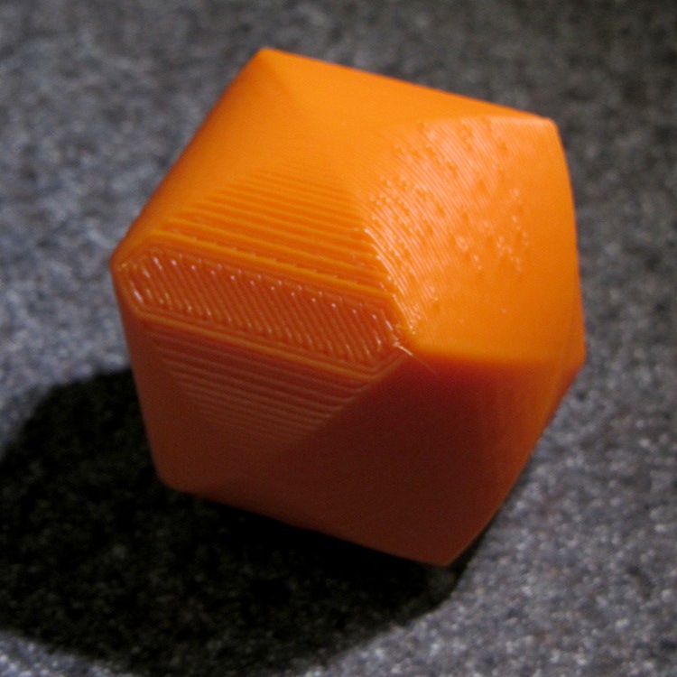
As you might expect, changing the layer thickness to 0.1 mm = 100 μm dramatically improves the appearance of the dummy 9 mm Luger bullet on the left, compared to the 0.25 mm = 250 μm layers on the right:
Dummy 9 mm Luger cartridges – 0.1 mm layer – overview
The inside edge of the translucent skirt around the quartet measured 90 to 110 μm, so the layer height is spot on:
Dummy 9 mm Luger bullets – 0.1 mm layer – overhead on platform
That required no adjustments to the M2 at all; It Just Works. Admittedly, that’s with a custom platform and firm supports replacing the springs, plus better Z-axis homing, but the overall structure was fine to start with.
I used the same Slic3r settings as before, with the only change being the layer thickness. Letting it pick the layer width might produce better results, but a 0.35 mm nozzle won’t go much narrower than 0.40 mm anyway.
A closer look at the bullet show the thinner layers provide a better rendition of the stretched sphere forming the nose; it’s less pointy than the one assembled from thicker layers:
Dummy 9 mm Luger bullets – 0.1 mm layer – side
The nose closes better with thinner layers:
Dummy 9 mm Luger bullets – 0.1 mm layer – nose
None of that really matters for this application, but it’s a useful data point.
The downside is that printing with thinner layers requires more time: a single bullet (of 16) requires 2.2 minutes at 250 μm and (of 4) 9 minutes at 100 μm. The simple ratio of layer thicknesses predicts a factor of 2.5, not 4, but the skirt requires a larger fraction of the total time. The estimated time for a 4×4 array at 100 μm comes out at 5.2 minutes each, a factor of 2.4, which is close enough.
Although 100 μm certainly looks better, it doesn’t really improve anything for most of the blocky stuff I make…
That’s a snap cap on the left and a real 9 mm Luger cartridge on the right. The holes in the dummy brass indicate that they are absolutely, positively, unquestionably not loaded cartridges.
Start by drilling a 1/8 inch hole in the side of each unfired, primerless case:
Dummy 9 mm Luger – drilling case
I set up the chuck on the rotary table, thinking I might drill three holes in each cartridge, but came to my senses. It’s lined up by eye, flush with the end of the jaws, and the hole is just above the inside of the base.
The solid model has the same overall length and proportion as a 115 grain FMJ bullet, but doesn’t match the proper ogive or base diameter. Basically, I stretched a 9 mm sphere and stuck it atop a slightly tapered base cylinder:
Dummy 9 mm Luger bullet – solid model
For reasons I don’t profess to understand, the sphere has a slightly different diameter at its equator than the top of the cylinder, even though they’re both the same BulletOD diameter with the same number of faces. Fortunately, that didn’t affect the final results.
Print up a handful of the things:
Dummy 9 mm Luger bullets – on platform
The shadow from the flash makes the bases look slightly fatter than they really are.
Using a thinner layer would look better in this orientation. They’d definitely look better if they were split, printed with the long axis parallel to the plate, and glued together, as the grain would run lengthwise; I’m not sure there’s enough room for alignment pins, though.
At this diameter and number of faces, the M2 produces almost perfectly accurate dimensions, so the bullets press-fit just like you’d expect. They’re twisted into a dab of urethane glue inside the brass that foams just enough to hold them place.
Rather than use a real seating die, I deployed a closed chuck on the drill press. The trick is to set the depth stop to produce slightly too-long cartridges, then shim the platform without changing the stop and seat the bullet to the proper depth:
Dummy 9 mm Luger – seating bullet
The OAL tolerance for various 9 mm Luger cartridges seems to range from 1.08 inch to 1.17 inch, so anything in that range should be fine. I used 1.10 inch.
These are not intended for firing. You could fire them with just a primer (in a non-drilled case) and (maybe) not melt or shatter the plastic, but they’re slightly larger than the nominal 8.82 mm land diameter and won’t obturate or spin-stabilize worth diddly: expect short range and keyholing.
The sectional density is a whopping 0.008, should you keep track of such things: 0.47 gram = 7.2 grain. Note that the US small arms definition of sectional density has units of pound/inch2, not the pound/foot2 you’ll find right next to values computed using inches; the magic number 1/7000 just converts from grains to pounds. In the rest of the (metric) world, it’s entirely different.
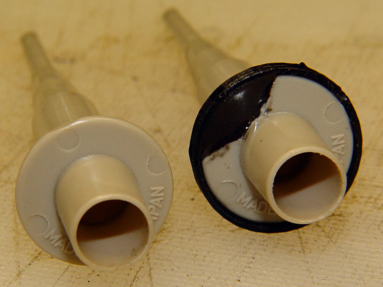
Quite some time ago I manage to break the finger flange on one of my scope probes and, what with it being made of an un-glueable engineering plastic, a simple repair job failed quickly. It’s entirely round and a perfect lathe project, but … this is easier:
HP Scope Probe Flange Repair
You can see remnants of that failed repair just below the fracture:
HP scope probe flanges – repair disk
Some epoxy around the rim of the flange, plus filling the missing sector, looks about as grubby as you’d expect:
HP Scope Probes – rear
That’s a tiny zit at about 1 o’clock which came off with fingernail pressure.
From the business end, it actually looks pretty snappy:
HP Scope Probes – front
I’m mildly tempted to preemptively reinforce the other probes…
The OpenSCAD source code joins two parts with coincident faces, but it worked out OK for once:
// Tek Scope Probe Flange
// Ed Nisley KE4ZNU November 2013

//- Extrusion parameters must match reality!
//  Print with 2 shells and 3 solid layers

ThreadThick = 0.25;
ThreadWidth = 0.40;

HoleWindage = 0.2;

Protrusion = 0.1;			// make holes end cleanly

function IntegerMultiple(Size,Unit) = Unit * ceil(Size / Unit);

//----------------------
// Dimensions

FlangeOD = 16.0;
FlangeID = 8.75;
FlangeThick = IntegerMultiple(1.25,ThreadThick);

DiskOD = FlangeOD + 4*ThreadWidth;
DiskThick = FlangeThick + 4*ThreadThick;

NumSides = 8*4;

//----------------------
// Useful routines

module PolyCyl(Dia,Height,ForceSides=0) {			// based on nophead's polyholes

  Sides = (ForceSides != 0) ? ForceSides : (ceil(Dia) + 2);

  FixDia = Dia / cos(180/Sides);

  cylinder(r=(FixDia + HoleWindage)/2,
           h=Height,
	   $fn=Sides);
}

module ShowPegGrid(Space = 10.0,Size = 1.0) {

  Range = floor(50 / Space);

	for (x=[-Range:Range])
	  for (y=[-Range:Range])
		translate([x*Space,y*Space,Size/2])
		  %cube(Size,center=true);

}

//----------------------
// Build it

ShowPegGrid();

	difference() {
		union() {
			translate([0,0,2*ThreadThick])
				cylinder(r=DiskOD/2,h=DiskThick,$fn=NumSides);			// main repair part
			cylinder(r1=(DiskOD - 2*ThreadWidth)/2,r2=DiskOD/2,h=2*ThreadThick,$fn=NumSides);
		}
		translate([0,0,(DiskThick - FlangeThick)])				// flange clearance
			PolyCyl(FlangeOD,2*FlangeThick,NumSides);
		translate([0,0,-DiskThick/2])
			PolyCyl(FlangeID,2*DiskThick,NumSides);
	}
I’ve been working on an object (more on this later) that requires precise alignment of two parts that capture a nut deep inside. This calls for alignment pins, similar to the ones I used for, say, the Triple-Cylinder Thing:
Cylinder Thing – rotated
The general idea is to design holes that fit the pins, then locate them at the parting line of the model, where they’re subtracted from the solid and appear in exactly the proper places when the model splits for printing:
Cylinder Thing – alignment pegs
You slather solvent glue on both halves, jam pins into the holes, slap the parts together, and clamp until cured. Works fine, I use pins all over the place.
The gotcha of using just a (polygonal) cylinder as the hole: if you glue one end of the pin at a time, a small rim of dissolved plastic may form around the pin at the surface. That can bond the two halves together or prevent them from joining properly after being disassembled.
Sooo, here’s a new alignment pin hole with a gutter around the pin on both surfaces to capture the glop:
Alignment pin hole – overview
Remember, that’s the negative volume that will hold the pin, not the pin itself!
Here’s how it works in real plastic, with a 1.75 mm peg glued into one hole with a bit of crud in the gutter:
Alignment Hole and Pin
The secret to making the gutter work: offset the second layer by half the thread width, so that it’s reasonably well supported on the first layer. If you don’t do that, the inner layers simply drop down through the hole and fill the gutter. Even doing that, notice the distortion of the first few layers inside the hole.
The OpenSCAD source code looks about like you’d expect:
Ideally, the pin length should extend at least two diameters into each side of the object, but you can feed in whatever you need to make it come out right.
The PolyCyl() routine produces a low-vertex-count polygon that circumscribes the nominal diameter, which is what you need for vertical holes in 3D printed objects:
module PolyCyl(Dia,Height,ForceSides=0) {			// based on nophead's polyholes

  Sides = (ForceSides != 0) ? ForceSides : (ceil(Dia) + 2);

  FixDia = Dia / cos(180/Sides);

  cylinder(r=(FixDia + HoleWindage)/2,
           h=Height,
	   $fn=Sides);
}
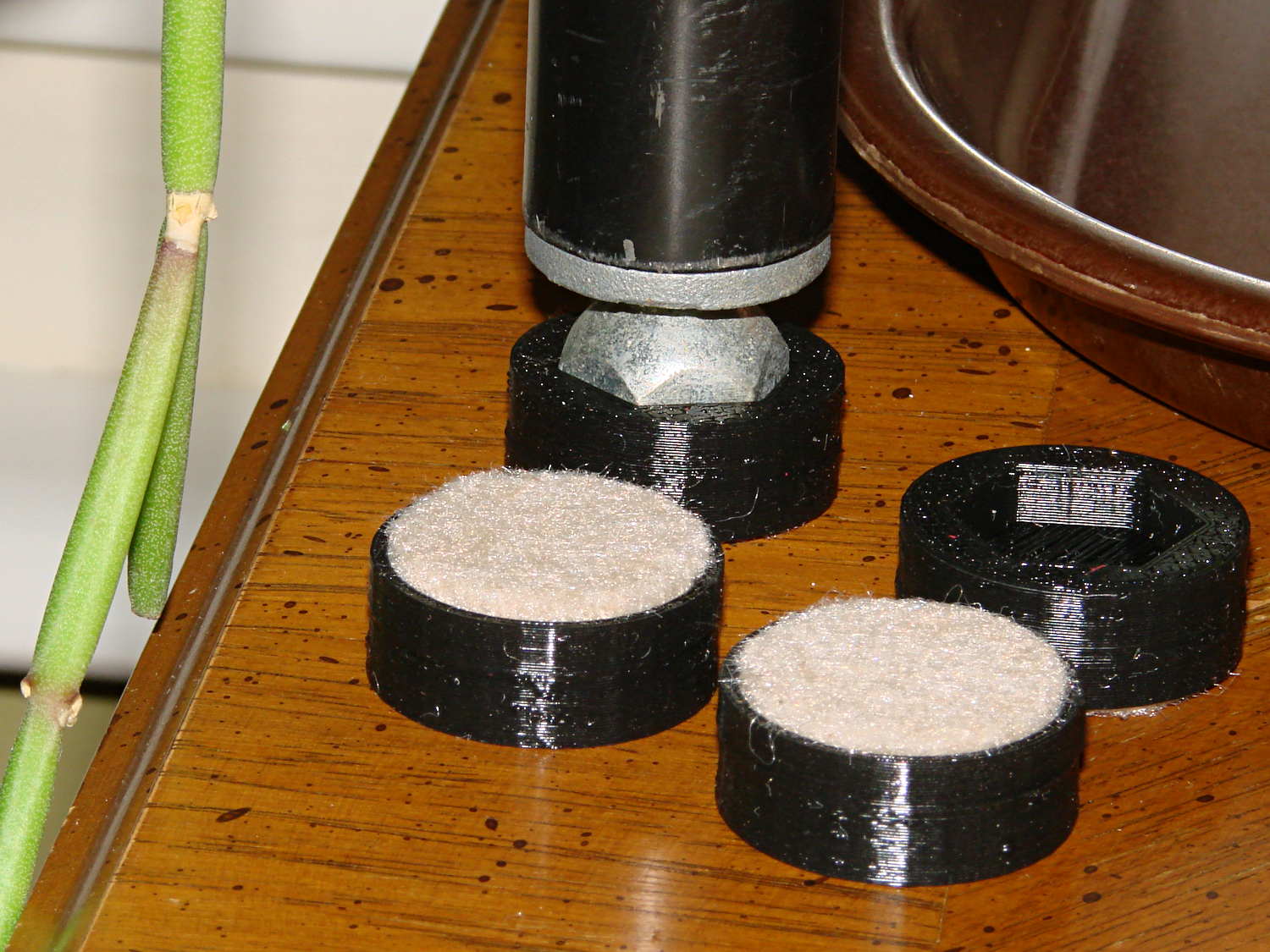
The houseplants have migrated indoors after spending a summer charging up in the sun on the patio, which means it’s time to replace the silicone rubber feet on the bottom of the plant shelves. This year, I printed a set of feet to fit the hex-head adjustable feet:
Plant Stand Foot – installed
The pencil-stem plant on the left, for whatever it’s worth, is a perfectly healthy Rhipsalis that greatly enjoyed the summer sun.
The feet print upside-down to give the surface around the hex a smooth finish. I used Slic3r’s Hilbert Curve for pattern a bit more interesting than the usual parallel lines:
Plant Shelf Foot – as built
The Hilbert curve doesn’t fit neatly into a non-rectangular shape, but it’s close enough.
The solid model includes the support structure:
Plant Shelf Foot – solid model – bottom
Which pops out cleanly:
Plant Shelf Foot – support material detail
Yes, that’s a shred of red filament embedded on the left side. Cleanliness is next to impossible…
The fuzzy felt feet come from a 6 mm thick slab of the stuff:
Plant Shelf Foot – cutting felt plugs
The round socket wall leaves about 2 mm of felt showing at the bottom; it’s not very compressible and that should suffice to keep the plastic off the table.
The OpenSCAD source code:
// Feet for a wire-shelf plant stand
// Ed Nisley KE4ZNU October 2013

Layout = "Build";			// Show Build

Support = true;

//- Extrusion parameters must match reality!
//  Print with 2 shells and 3 solid layers

ThreadThick = 0.25;
ThreadWidth = 0.40;

HoleWindage = 0.2;

Protrusion = 0.1;			// make holes end cleanly

//----------------------
// Dimensions

StandFootOD = 18.0;			// hex across flats
StandFootDepth = 5.0;		//  ... socket depth

FeltPadOD = 25.0;			// felt foot diameter
FeltPadDepth = 4.0;			//  ... depth

FootBaseThick = 6*ThreadThick;	// between foot and pad
FootWall = 4*ThreadWidth;		// around exterior

FootOD = 2*FootWall + max(StandFootOD,FeltPadOD);
echo(str("Foot OD: ",FootOD));

FootTall = StandFootDepth + FootBaseThick + FeltPadDepth;
echo(str(" ... height: "),FootTall);

NumSides = 8*4;

//----------------------
// Useful routines

module FootPad() {

	difference() {

		cylinder(r=FootOD/2,h=FootTall,$fn=NumSides);

		translate([0,0,FeltPadDepth + FootBaseThick])
			PolyCyl(StandFootOD,2*StandFootDepth,6);

		translate([0,0,-Protrusion])
			PolyCyl(FeltPadOD,(FeltPadDepth + Protrusion),NumSides);

	}
}

// Locating pin hole with glue recess

module LocatingPin() {

	translate([0,0,-ThreadThick])
		PolyCyl((PinOD + 2*ThreadWidth),2*ThreadThick,4);
	translate([0,0,-(PinLength/2 + ThreadThick)])
		PolyCyl(PinOD,(PinLength + 2*ThreadThick),4);

}

module PolyCyl(Dia,Height,ForceSides=0) {			// based on nophead's polyholes

  Sides = (ForceSides != 0) ? ForceSides : (ceil(Dia) + 2);

  FixDia = Dia / cos(180/Sides);

  cylinder(r=(FixDia + HoleWindage)/2,
           h=Height,
	   $fn=Sides);
}

module ShowPegGrid(Space = 10.0,Size = 1.0) {

  Range = floor(50 / Space);

	for (x=[-Range:Range])
	  for (y=[-Range:Range])
		translate([x*Space,y*Space,Size/2])
		  %cube(Size,center=true);

}

//-------------------
// Build it...

ShowPegGrid();

if (Layout == "Show")
	FootPad();

if (Layout == "Build") {
	translate([0,0,FootTall])
		rotate([180,0,0])
			FootPad();
	if (Support)
		color("Yellow")
			for (Seg=[0:5]) {
				rotate(30 + 360*Seg/6)
				translate([0,0,(StandFootDepth - ThreadThick)/2])
					cube([(StandFootOD - 3*ThreadWidth),
						  2*ThreadWidth,
						  (StandFootDepth - ThreadThick)],
						  center=true);
				}
}
The Makergear M2 comes with a plastic block that covers the X-min switch wiring and anchors the end of the filament guide. Because the guide wasn’t anchored to the block, bumping the guide tended to bend the filament where it exited the block. To prevent that, I hot-melt-glued the guide to the block, which really wasn’t particularly elegant. This picture shows the X-min switch relocated to contact the platform, with the slightly out of focus blob anchoring the guide off to the right:
M2 – Z-min switch at rear X gantry
Makergear provides STL files of the M2’s printable bits, including several versions of the wire cover block. This corresponds to the one on my M2, although the rounded edges don’t come through in the plastic very welll:
Stock M2 Wire Cover Filament Guide – solid model
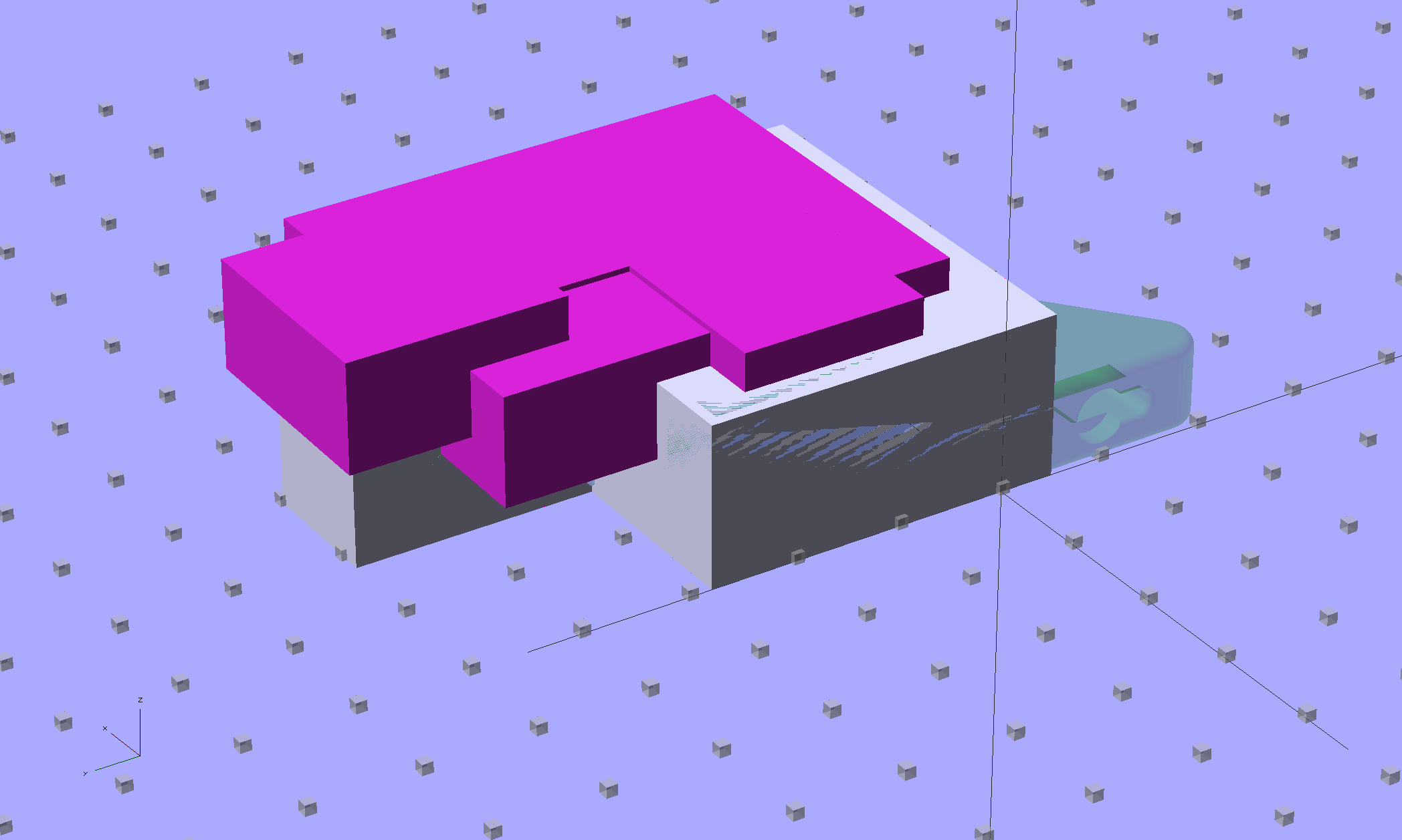
Because STL files aren’t editable, I reverse-engineered the dimensions into an OpenSCAD model that I could use as the basis for a different guide. This is just the basic wire cover, minus the filament guide extension, plus a flat end that wraps around the edge of the chassis:
M2 Wire Cover – reverse engineered
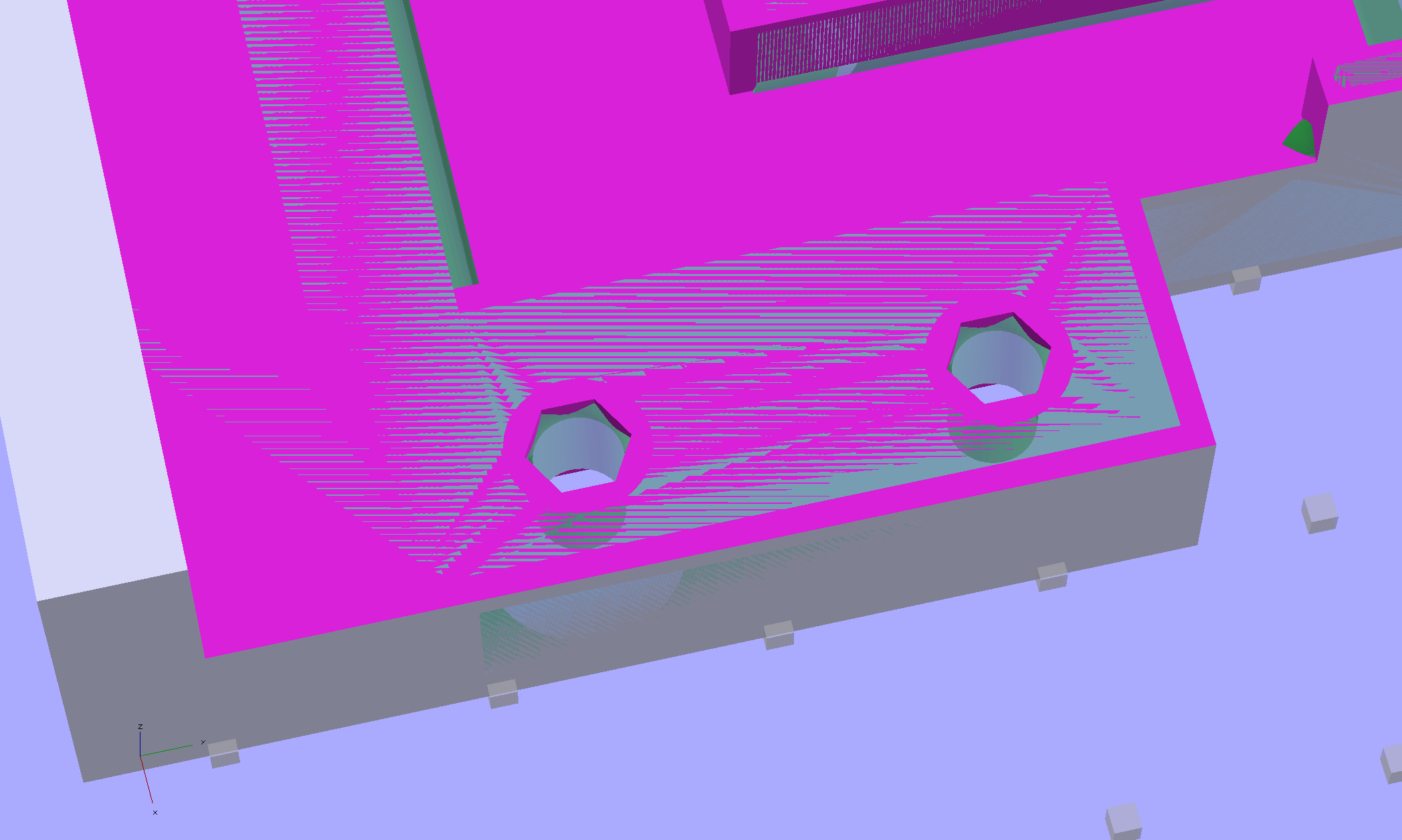
The trick is to import the STL into OpenSCAD, then build a model that matches the key dimensions. Fortunately, Makergear used hard metric sizes for everything, so most of the numbers came out as integers or single-place decimals:
The shimmer indicates coincident surfaces; that’s ordinarily a Very Bad Thing, but in this case it shows that the dimensions match. The top of the holes have neat hexagonal patterns where my straight-sided PolyHoles extend through their chamfered circular holes:
Unlike my from-scratch OpenSCAD models, this one bristles with magic numbers that describe the dimensions of the M2 STL model. The basic shape comes from an extruded polygon matching the outside walls, another extruded polygon knocking out the wire channel, then cubes lopping off the top surfaces:
M2 Wire Cover Filament Guide – overlay – F12 view
The end result of all that thrashing around has a certain Soviet Concrete look to it:
M2 Wire Cover – OpenSCAD solid model
This version lacks the filament guide; I wanted to make sure all the protrusions and channels fit, which they sort of did:
M2 reverse engineered wire cover – installed
The next version will have slightly more clearance on the side and slightly less on the top; that’s easy to do now that I have an editable OpenSCAD model.
The OpenSCAD source code:
// Improved M2 filament guide and X-min switch wire guide
// Ed Nisley KE4ZNU - Oct 2013

function IntegerMultiple(Size,Unit) = Unit * ceil(Size / Unit);

Protrusion = 0.1;

HoleWindage = 0.2;

//- Sizes

PlateMinThick = 8.0;				// basic thickness excluding wire guides
PlateLength = 5.0;					// from side of frame beyond top wire guide

TopGuideLength = 7.0;				// protrusion from plate

PlateThick = PlateMinThick + TopGuideLength;

echo(str("Total thickness: ",PlateThick));

//- Adjust hole diameter to make the size come out right

module PolyCyl(Dia,Height,ForceSides=0) {			// based on nophead's polyholes

  Sides = (ForceSides != 0) ? ForceSides : (ceil(Dia) + 2);

  FixDia = Dia / cos(180/Sides);

  cylinder(r=(FixDia + HoleWindage)/2,h=Height,$fn=Sides);
}

//- Put peg grid on build surface

module ShowPegGrid(Space = 10.0,Size = 1.0) {

  RangeX = floor(100 / Space);
  RangeY = floor(125 / Space);

	for (x=[-RangeX:RangeX])
	  for (y=[-RangeY:RangeY])
		translate([x*Space,y*Space,Size/2])
		  %cube(Size,center=true);

}

//- Define basic block shape
//  Mostly reverse engineered from
//    https://github.com/MakerGear/M2/blob/master/Printed%20Parts/STL/M2%20X%20Endstop%20Wire%20Cover%20with%20Filament%20Guide.stl
//	Hence all the magic numbers...

module BaseBlock() {

SideGuideLength = 4.0;				// protrusion = even with frame interior
ChannelDepth = 4.5;					// wiring channel
FrameOffset = 28;

	translate([18,FrameOffset,0]) {			// align neatly for later processing

		if (true)
			color("Green",0.3)
				translate([-18,22,15])
					rotate([-90,0,-90])
						import("/mnt/bulkdata/Project Files/Thing-O-Matic/M2 Parts/Filament Guide/M2+X+Endstop+Wire+Cover+with+Filament+Guide.stl",
								convexity=10);

		difference() {
			linear_extrude(height=PlateThick,convexity=5)		// main block
				polygon(points=[[0,0],[0,22],[12,22],[12,7.5],[22,7.5],
								[22,-(PlateLength + FrameOffset)],[-18,-(PlateLength + FrameOffset)],
								[-18,0]
						]);

			for (i=[-1,0])
				translate([17,((i*15.0)+ 1.05),-Protrusion])
					rotate(180/6) {
						PolyCyl(3.1,(PlateMinThick + 2*Protrusion),6);		// screw holes
						PolyCyl(5.7,(3.0 + Protrusion),6);					//  ... countersink
					}

			translate([0,0,(PlateMinThick - ChannelDepth)])		// wire channel
				linear_extrude(height=15,convexity=5)
					polygon(points=[[2,-5],[2,19],[10,19],[10,-22],[-15,-22],[-15,-5]
							]);

			translate([-10,14,PlateMinThick])				// M2 frame
				rotate(-90)
					cube([42,35,10],center=false);

			translate([-5,5,(PlateMinThick + SideGuideLength)])	// shorten side guide
				cube([20,20,10],center="false");

		}
	}

}

//- Build it

ShowPegGrid();

BaseBlock();