Ed Nisley's Blog: Shop notes, electronics, firmware, machinery, 3D printing, laser cuttery, and curiosities. Contents: 100% human thinking, 0% AI slop.
Category: Software
General-purpose computers doing something specific
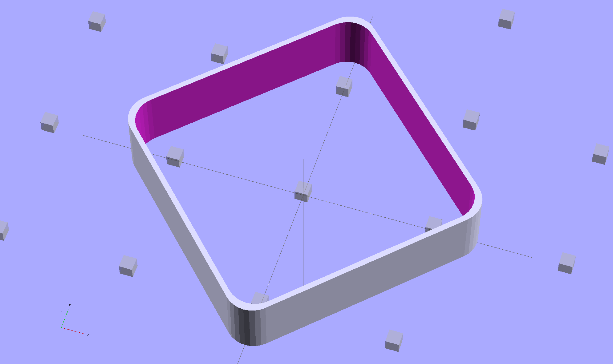
The latter, of course: I blundered the inner corner radius, which occasionally produced little tiny dots of infill that shouldn’t be there. Just one of those errors that hides in plain sight until something else goes wrong, then it’s obvious.
Rather than fix the Minkowski version, I rebuilt it using the hull() operator to shrinkwrap four cylinders for each solid, then remove the smaller block from the larger. Commenting out the hull() operators shows that the cylinders now line up properly:
Thinwall Open Box – un-hulled – solid model
The OpenSCAD source code:
// Thin wall open box calibration piece
// Adapted from Coasterman's Calibration set
// Ed Nisley - KE4ZNU - Dec 2011
// Adjust for Slic3r/M2 - March 2013
// Reworked for hull() with correct corner radii - April 2014

//-------
//- Extrusion parameters must match reality!
//  None of the fill parameters matter

ThreadThick = 0.20;
ThreadWidth = 0.40;

Protrusion = 0.1;           // make holes end cleanly

function IntegerMultiple(Size,Unit) = Unit * ceil(Size / Unit);

//-------
// Dimensions

Height = IntegerMultiple(5.0,ThreadThick);

WallThick = ThreadWidth;

CornerRadius = 2.0;
CornerSides = 4*8;

SideLen = 20.0 - 2*CornerRadius;

Rotation = 45;

//-------

module ShowPegGrid(Space = 10.0,Size = 1.0) {

  Range = floor(50 / Space);

    for (x=[-Range:Range])
      for (y=[-Range:Range])
        translate([x*Space,y*Space,Size/2])
          %cube(Size,center=true);
}

//-------

ShowPegGrid();

rotate(Rotation)
	difference() {
		hull() {
			for (i=[-1,1], j=[-1,1])
				translate([i*SideLen/2,j*SideLen/2,0])
					cylinder(r=CornerRadius,h=Height,$fn=CornerSides);
		}
		hull() {
			for (i=[-1,1], j=[-1,1])
				translate([i*SideLen/2,j*SideLen/2,-Protrusion])
					cylinder(r=(CornerRadius - WallThick),h=(Height + 2*Protrusion),$fn=CornerSides);
		}
	}
The Sony HDR-AS30V camera lens has a view angle of 120° or 170°, achieved by internal image processing rather than mechanical lens adjustments. For most action-camera purposes you don’t care about fisheye distortion, but sometimes a more rectilinear picture will look better, in which case the GIMP’s Lens Distortion filter comes in handy.
A still image at 120°, which doesn’t look all that bad, really:
Sony HDR-AS30V 120 angle – as captured
Applying Main=-25 gives this:
Sony HDR-AS30V 120 angle – corrected
A frame captured from video at 170°, with the overhead wires hanging upward:
Sony HDR-AS30V 170 angle – as captured
Applying Main=-25, Edge=-12.5, Zoom=+8 flattens them enough to be acceptable:
Sony HDR-AS30V 170 angle – corrected
The main effect of the Zoom parameter seems to be discarding the severely distorted remnants around the edges of the corrected 170° view. Sometimes, those pixels around the edges can be very, very important, so I’d rather make that decision after the fact.
A solderless breadboard sufficed for the simple circuitry behind the strobe controller:
Strobe Photography – control breadboard
I used a separate 7.5 V supply for the Arduino Pro Mini to keep the relay noise out of the VCC circuit, but that’s probably not really necessary; you could back-drive the Pro Mini’s regulator with +5 V and it’d be perfectly happy. There’s a +5 V wall wart for the relay, LEDs, and so forth.
Protip: you do not want to drive all the other circuitry through the Pro Mini’s tiny little regulator. Work out the power dissipation in the regulator caused by a 130 Ω relay, about 10 mA for the laser, 100 mA for the white LED, and whatever the Pro Mini draws. Yeah, some of those are intermittent loads, but work it out anyway.
A 1.5 V bench supply powers the Xenon strobe in place of the AA alkaline cell I used at first. The boost circuit pins the supply at 3 A for a few seconds, then settles at about 350 mA (!) while idling; no wonder the poor little AA cells don’t last very long!
The control program is also dead simple; it’s mostly a state machine that notices when the photocurrent drops to zero, then steps through a series of fixed delays while turning the laser, LED, and strobe outputs on and off.
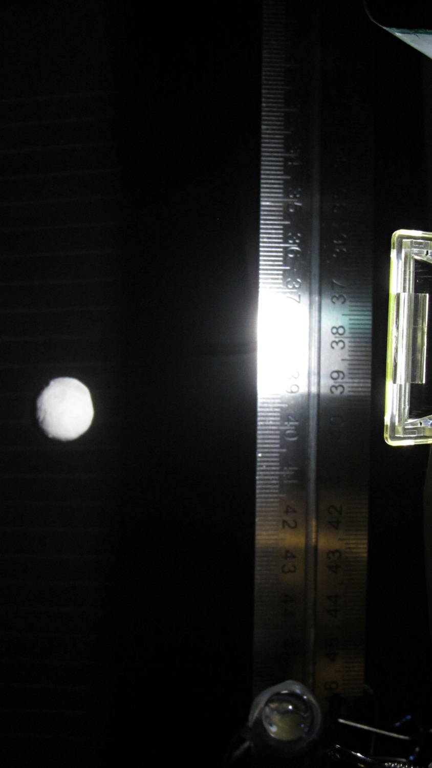
The default values highlight a falling object about 200 mm below the laser beam-break sensor, assuming you release the object just above the beam:
Ball at 200 mm – detail
The laser beam is at the 200 mm mark, so that ball passing 400 mm has dropped 200 mm.
The quadrature encoder knob recycles the same interrupt handler I used earlier, with the shaft button selecting either the LED delay (pushed) or the Xenon strobe delay (released). There’s precious little error checking, as befits a quick hack job, so use at your own risk…
The Arduino source code:
// Optical flash triggering
// Ed Nisley - KE4ANU - March 2014

//----------
// Pin assignments

const byte PIN_KNOB_A = 2;			// knob A switch - must be on ext interrupt 2
const byte PIN_KNOB_B = 4;			//  .. B switch
const byte PIN_KNOB_SWITCH = A3;	//  .. shaft push switch

const byte PIN_PHOTOCURRENT = A0;	// photodiode current input

const byte PIN_LASER = 8;   		// laser drive -active
const byte PIN_LED = 7;		   		// LED drive -active
const byte PIN_FLASH = 12;			// Xenon flash relay -active

const byte PIN_SYNC = 13;			// scope sync - and Arduino LED

//----------
// Constants

enum FALLING_STATES {F_IDLE,F_WAIT,F_DETECT,F_PREFALL,F_LED,F_MD,F_FLASH,F_CLEAR};

enum KNOB_STATES {KNOB_CLICK_0,KNOB_CLICK_1};

//----------
// Globals

const unsigned long UPDATEMS = 250;	// update displays only this many ms apart

volatile char KnobCounter = 0;
volatile byte KnobState;

byte Button, PrevButton;

byte Falling = F_IDLE;				// cold start the detection state machine

unsigned long FallStart;			// when we we detected the falling object

unsigned int DetectLevel = 200;		// ADC reading for object detection

unsigned int DelayLED = 1;			// ms from trigger detect to LED preflash

unsigned int DelayFlash = 180;		//  ... to Xenon flash

unsigned int DelayClear = 6000;		//  ... after impact to allow camera restart

const byte PulseLED = 50;			// ms LED on to pass motion detection threshold
const byte PulseFlash = 20;			// ms Xenon flash relay on

const unsigned int RelayAdvance = 3;	// ms relay activation to Xenon flash

unsigned long MillisNow;
unsigned long MillisThen;

//-- Helper routine for printf()

int s_putc(char c, FILE *t) {
  Serial.write(c);
}

//-- Knob interrupt handler

void KnobHandler(void)
{
	byte Inputs;
	Inputs = digitalRead(PIN_KNOB_B) << 1 | digitalRead(PIN_KNOB_A);  // align raw inputs
//	Inputs ^= 0x02;                             // fix direction

	switch (KnobState << 2 | Inputs) {
	case 0x00 : 				// 0 00 - glitch
        break;
	case 0x01 : 				 // 0 01 - UP to 1
        KnobCounter++;
		KnobState = KNOB_CLICK_1;
		break;
	case 0x03 : 				 // 0 11 - DOWN to 1
        KnobCounter--;
		KnobState = KNOB_CLICK_1;
		break;
	case 0x02 : 				 // 0 10 - glitch
        break;
	case 0x04 : 				 // 1 00 - DOWN to 0
        KnobCounter--;
		KnobState = KNOB_CLICK_0;
		break;
	case 0x05 : 				 // 1 01 - glitch
        break;
	case 0x07 : 				 // 1 11 - glitch
        break;
	case 0x06 : 				 // 1 10 - UP to 0
        KnobCounter++;
		KnobState = KNOB_CLICK_0;
		break;
	default :  					// something is broken!
        KnobCounter = 0;
		KnobState = KNOB_CLICK_0;
	}
}

//------------------
// Set things up

void setup() {

	pinMode(PIN_SYNC,OUTPUT);
	digitalWrite(PIN_SYNC,LOW);			// show we arrived

	pinMode(PIN_KNOB_B,INPUT_PULLUP);
	pinMode(PIN_KNOB_A,INPUT_PULLUP);
	pinMode(PIN_KNOB_SWITCH,INPUT_PULLUP);

    pinMode(PIN_LASER,OUTPUT);
    digitalWrite(PIN_LASER,HIGH);

    pinMode(PIN_LED,OUTPUT);
    digitalWrite(PIN_LED,HIGH);

    pinMode(PIN_FLASH,OUTPUT);
    digitalWrite(PIN_FLASH,HIGH);

	KnobState = digitalRead(PIN_KNOB_A);
	Button = PrevButton = !digitalRead(PIN_KNOB_SWITCH);

	attachInterrupt((PIN_KNOB_A - 2),KnobHandler,CHANGE);

	Falling = F_IDLE;

	Serial.begin(9600);
	fdevopen(&s_putc,0);				// set up serial output for printf()

	printf("Xenon Flash Trigger\r\nEd Nisley - KE4ZNU - March 2014\r\n");

	MillisThen = millis();

}

//------------------
// Go flash!

void loop() {

	MillisNow = millis();

	if (KnobCounter) {
		Button = !digitalRead(PIN_KNOB_SWITCH);
		if (Button)
			DelayLED += KnobCounter;
		else
			DelayFlash += KnobCounter;

		DelayLED = min(DelayLED,DelayFlash - PulseLED);
		printf("Knob: %d, LED: %d, Flash: %d\n",KnobCounter,DelayLED,DelayFlash);
		KnobCounter = 0;
	}

	digitalWrite(PIN_SYNC,HIGH);

	switch (Falling) {
	case F_IDLE :								// turn on laser for object detection
		digitalWrite(PIN_LASER,LOW);
		printf("Laser on, stabilizing... ");
		while (analogRead(PIN_PHOTOCURRENT) <= DetectLevel) {
			printf("*");
		}
		printf("\nReady!\n");
		Falling = F_WAIT;
		break;
	case F_WAIT :								// record starting time of beam break
		if (analogRead(PIN_PHOTOCURRENT) < DetectLevel) {
			FallStart = millis();
			Falling = F_DETECT;
		}
		break;
	case F_DETECT :								// turn off laser to signal detection
		digitalWrite(PIN_LASER,HIGH);
		Falling = F_PREFALL;
		break;
	case F_PREFALL :							// turn on LED to trigger camera motion detection
		if ((millis() - FallStart) >= DelayLED) {
			digitalWrite(PIN_LED,LOW);
			Falling = F_LED;
		}
		break;
	case F_LED : 								// turn off LED
		if ((millis() - FallStart) >= (DelayLED + PulseLED)) {
			digitalWrite(PIN_LED,HIGH);
			Falling = F_MD;
		}
		break;
	case F_MD :									// fire the strobe to take picture
		if ((millis() - FallStart) >= (DelayFlash - RelayAdvance)) {
			digitalWrite(PIN_FLASH,LOW);
			Falling = F_FLASH;
		}
		break;
	case F_FLASH :								// turn off strobe relay
		if ((millis() - FallStart) >= (DelayFlash - RelayAdvance + PulseFlash)) {
			digitalWrite(PIN_FLASH,HIGH);
    		printf("Flash with LED delay: %d, Xenon delay: %d ...",DelayLED,DelayFlash);
			Falling = F_CLEAR;
		}
		break;
	case F_CLEAR :								// wait for camera to recycle
		if ((millis() - FallStart) >= DelayClear) {
			printf("done\n");
			Falling = F_IDLE;
		}
		break;
	default :
		printf("** Bad Falling state: %02X",Falling);
		Falling = F_IDLE;
	}

	digitalWrite(PIN_SYNC,LOW);

	if ((MillisNow - MillisThen) > UPDATEMS) {
//		printf("State: %02X\n",Falling);
		MillisThen = MillisNow;
	}

}
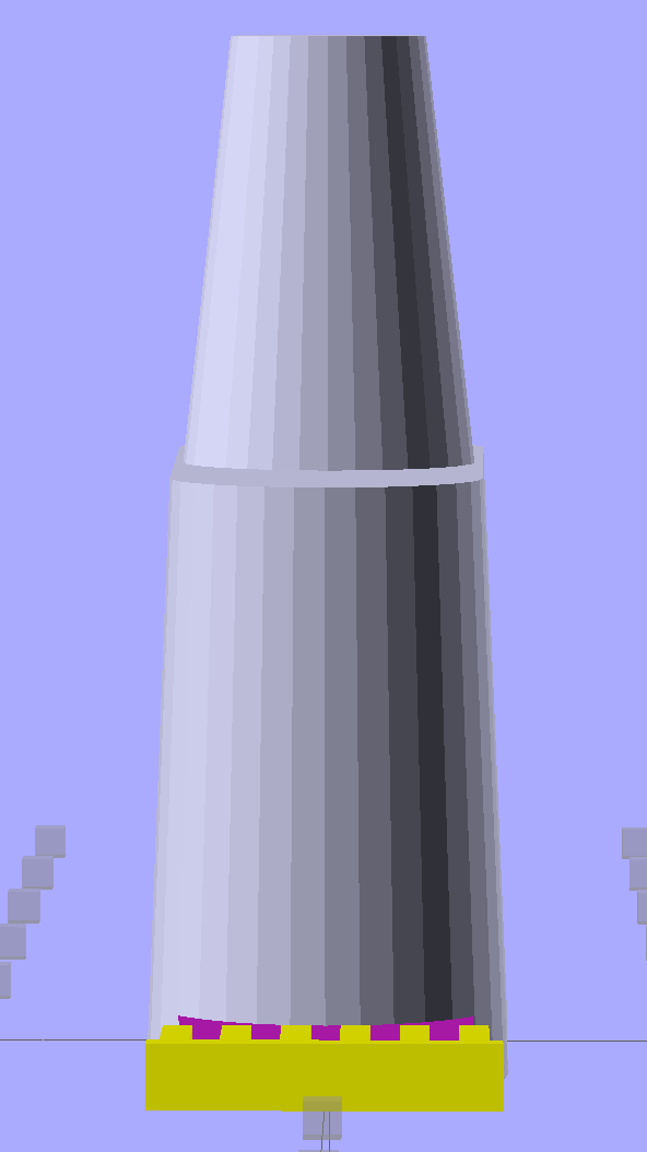
The game plan: drop a small object through a laser beam that shines on a photodiode, thus causing an electrical signal that triggers various flashes and cameras and so forth and so on. This fixture holds the laser and photodiode in the proper orientation, with enough stability that you (well, I) can worry about other things:
Laser-photodiode fixture – on blade
It’s mounted on the blade of a dirt-cheap 2 foot machinist’s square clamped to the bench which will probably get a few holes drilled in its baseplate for more permanent mounting.
The solid model looks about like you’d expect:
Laser-photodiode fixture – solid model
There’s a small hole in the back for an 8-32 setscrew that locks it to the blade; the fit turned out snug enough to render the screw superfluous. I added those two square blocks with the holes after I taped the wires to the one in the picture.
The two semicircular (well, half-octagonal) trenches have slightly different diameters to suit the heatshrink tubing around the photodiode (a.k.a., IR LED) and brass laser housing. A dab of fabric adhesive holds the tubes in place, in addition to the Gorilla Tape on the ends.
The laser came focused at infinity, of course. Unscrewing the lens almost all the way put the focus about 3/4 of the way across the ring; call it 40 mm. The beam is rectangular, about 1×2 mm, at the center of the ring, and I rotated the body to make the short axis vertical; that’s good enough for my purposes.
The cable came from a pair of cheap earbuds with separate Left/Right pairs all the way from the plug.
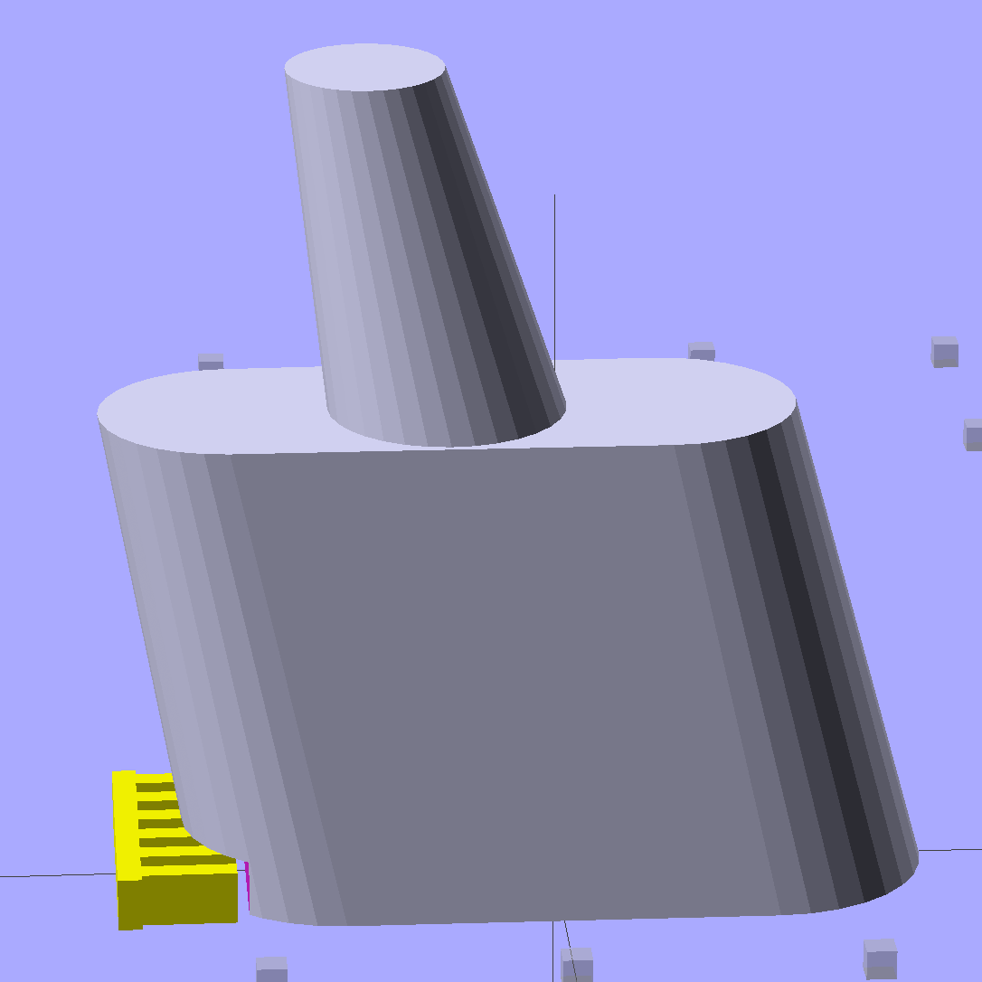
The model builds in one piece, of course, and pops off the platform ready to use:
Laser-photodiode fixture – on platform
If you were doing this for an analytic project, you’d want a marker for the beam centerline on the vertical scale, but that’s in the nature of fine tuning. As it stands, the beam sits 8 mm above the base and flush with the top surface of the ring; if that were 10 mm, it’d be easier to remember.
The OpenSCAD source code has a few tweaks and improvements:
// Laser and LED-photodiode break-beam sensor
// Ed Nisley - KE4ZNU - March 2014

Layout = "Show";			// Build Show Ring Mount Guide

//- Extrusion parameters must match reality!
//  Print with 2 shells and 3 solid layers

ThreadThick = 0.20;
ThreadWidth = 0.40;

HoleWindage = 0.2;			// extra clearance

Protrusion = 0.1;			// make holes end cleanly

AlignPinOD = 1.70;			// assembly alignment pins: filament dia

inch = 25.4;

function IntegerMultiple(Size,Unit) = Unit * ceil(Size / Unit);

//----------------------
// Dimensions

LaserOD = 6.0;				// brass focus tube
LaserLength = 20.0;			//  ... wire clearance

SensorOD = 6.5;				// including light shield
SensorLength = 20.0;		//  ... wire clearance

RingSize = [50.0,70.0,8.0,8*4];	// support ring dimensions
RING_ID = 0;
RING_OD = 1;
RING_THICK = 2;
RING_SIDES = 3;

StrutWidth = 2.5;					// strut supporting this thing
StrutLength = 26.5;

StrutBlock = [10.0,35.0,20.0];		// block around the clearance slot
BLOCK_WIDTH = 0;
BLOCK_LENGTH = 1;
BLOCK_HEIGHT = 2;

StrutScrewTap = 2.7;				// 6-32 SHCS

GuideID = 4.0;						// guide for cables
GuideOD = 3*GuideID;

BuildSpace = 3.0;					// spacing between objects on platform

//----------------------
// Useful routines

module PolyCyl(Dia,Height,ForceSides=0) {			// based on nophead's polyholes

  Sides = (ForceSides != 0) ? ForceSides : (ceil(Dia) + 2);

  FixDia = Dia / cos(180/Sides);

  cylinder(r=(FixDia + HoleWindage)/2,
           h=Height,
           $fn=Sides);
}

module ShowPegGrid(Space = 10.0,Size = 1.0) {

  RangeX = floor(100 / Space);
  RangeY = floor(125 / Space);

	for (x=[-RangeX:RangeX])
	  for (y=[-RangeY:RangeY])
		translate([x*Space,y*Space,Size/2])
		  %cube(Size,center=true);

}

module Ring() {

	difference() {
		union() {
			rotate(180/RingSize[RING_SIDES])
				cylinder(d=RingSize[RING_OD],h=RingSize[RING_THICK],
						$fn=RingSize[RING_SIDES]);
			translate([-LaserOD,(-LaserLength - RingSize[RING_ID]/2),0])
				cube([2*LaserOD,LaserLength,RingSize[RING_THICK]],center=false);
			translate([-SensorOD,(-0*SensorLength + RingSize[RING_ID]/2),0])
				cube([2*SensorOD,SensorLength,RingSize[RING_THICK]],center=false);
		}
		rotate(180/RingSize[RING_SIDES])
			translate([0,0,-Protrusion])
				cylinder(d=RingSize[RING_ID],h=(RingSize[RING_THICK] + 2*Protrusion),
						$fn=RingSize[RING_SIDES]);
		translate([0,0,RingSize[RING_THICK]])
			rotate([90,0,0]) rotate(180/8)
				PolyCyl(LaserOD,3*LaserLength,8);
		translate([0,0,RingSize[RING_THICK]])
			rotate([-90,0,0]) rotate(180/8)
				PolyCyl(SensorOD,3*SensorLength,8);
	}
}

module Mount() {
	translate([0,0,StrutBlock[2]/2])
		difference() {
			cube(StrutBlock,center=true);
			cube([StrutWidth,StrutLength,2*StrutBlock[2]],center=true);
			translate([0,-StrutLength/3,0])
				rotate([90,0,0])
					PolyCyl(StrutScrewTap,StrutLength/2,6);
		}
}

module Guide() {

	difference() {
		translate([0,0,RingSize[RING_THICK]/2])
			cube([GuideOD,GuideOD,RingSize[RING_THICK]],center=true);
		translate([0,0,-Protrusion]) rotate(180/8)
			PolyCyl(GuideID,(RingSize[RING_THICK] + 2*Protrusion),8);
	}
}

module Assembly() {
	Ring();
	translate([(RingSize[RING_OD]/2 + StrutBlock[BLOCK_LENGTH]/2
				- (StrutBlock[BLOCK_LENGTH] - StrutLength)/2) + Protrusion,0,0])
		rotate(90)
			Mount();
	for (i=[-1,1])
		translate([(RingSize[RING_OD]/2 + GuideID/2),
				  i*(StrutBlock[BLOCK_WIDTH]/2 + GuideID),
				  0])
			Guide();
}

//- Build it

ShowPegGrid();

if (Layout == "Ring") {
	Ring();
}

if (Layout == "Mount") {
	Mount();
}

if (Layout == "Guide") {
	Guide();
}

if (Layout == "Show") {
	Assembly();
}

if (Layout == "Build") {

	translate([-5/2,-5/2,0])
		cube(5);
}
Although commenting out an undesired variable isn’t fashionable, OpenSCAD doesn’t have a practical mechanism to set specific values based on a control variable:
if-then-else deals with geometric objects
(boolean)?when_true:when_false (the ternary operator) doesn’t scale well
You could, of course, depend on OpenSCAD’s behavior of using the last (in syntactic order) instance of a “variable”, but IMHO that’s like depending on semantic whitespace.
In any event, the rest of the block builds itself around those three values by recomputing all of its dimensions.
The Browning OEM block looks like this:
Browning Hi-Power Magazine Block – solid model – BHP OEM
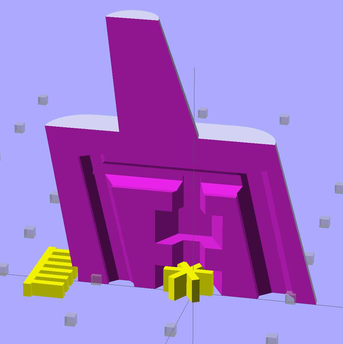
The Generic floorplate has a much larger spring retaining crimp, so the block has far more overhang:
Browning Hi-Power Magazine Block – solid model – Generic 1
As before, the yellow widgets are built-in support structures separated from the main object by one thread thickness and width. That seems to maintain good vertical tolerance and allow easy removal; the structures snap free with minimal force. A closeup look shows the gaps:
Browning Hi-Power Magazine Block – solid model – Generic 1 – support detail
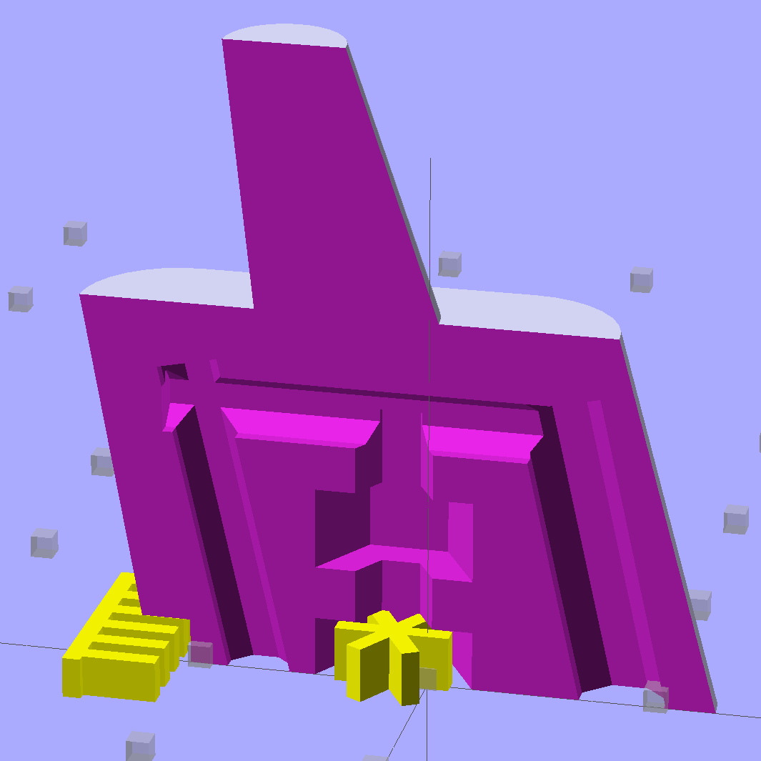
The main shape now has a 2 mm taper to ease the magazine spring past the upper edge of the block. The horn remains slightly inset from the side walls to ensure that the whole thing remains manifold:
Browning Hi-Power Magazine Block – solid model – Generic 1 – whole end
The whole object looks about the same, though:
Browning Hi-Power Magazine Block – solid model – Generic 1 – whole side
The shape descends from the geometry I used for the stainless steel block, with the additional internal channel (on the right in the models) to be filled with steel-loaded epoxy during assembly. That should make the whole block sufficiently robust that you must destroy the floorplate and distort the spring to get it out; wrecking the magazine’s innards should count as not “readily” modifiable.
Some destructive testing seems to be in order…
The OpenSCAD source code:
// Browning Hi-Power Magazine Plug
// Ed Nisley KE4ZNU December 2013
// February 2014 - easier customization for different magazine measurements
Layout = "Whole"; // Whole Show Split
// Whole = upright for steel or plastic
// Show = section view for demo, not for building
// Split = laid flat for plastic show-n-tell assembly
AlignPins = true && (Layout == "Split"); // pins only for split show-n-tell
Support = true && (Layout != "Split"); // no support for split, optional otherwise
// Define magazine measurements
//BlockData =  [-0.5, 1.5, 11.5];	// Browning OEM
BlockData = [-1.5, 2.0, 9.0];		// Generic 1

SCREWOFFSET = 0;
CRIMPHEIGHT = 1;
CRIMPDISTANCE = 2;
//- Extrusion parameters must match reality!
// Print with 2 shells and 3 solid layers
ThreadThick = 0.20;
ThreadWidth = 0.40;
HoleWindage = 0.2;
Protrusion = 0.1; // make holes end cleanly
function IntegerMultiple(Size,Unit) = Unit * ceil(Size / Unit);
//----------------------
// Dimensions
Angle = 12.5; // from vertical
SpringID = 10.3; // magazine spring curvature (measure with drill shank)
SpringRadius = SpringID / 2;
Taper = 2.0; // total taper toward top
Length = 24.5; // front-to-back perpendicular to magazine shaft
Height = 17.0; // bottom-to-top, parallel to magazine shaft
RectLength = Length - SpringID; // block length between end radii
HornBaseOD = 8.0; // fits between follower pegs to prevent shortening
HornTipOD = 5.0;
HornAddTip = (HornTipOD/2)*tan(Angle);
HornAddBase = (HornBaseOD/2)*tan(Angle);
HornAddLength = HornAddTip + HornAddBase + 2*Protrusion;
HornLength = 12.0; // should recompute ODs, but *eh*
ScrewOD = 3.0 - 0.25; // screw hole dia - minimal thread engagement
ScrewLength = Height - 5.0;
ScrewOffset = BlockData[SCREWOFFSET]; // ... from centerline on XY plane
NutOD = 5.8; // hex nut dia across flats
NutThick = 2.4; // ... generous allowance for nut
NutTrapLength = 1.5*NutThick; // allow for epoxy buildup
NutTrapBaseHeight = 5.0; // ... base height from floor plate
CrimpHeight = IntegerMultiple(BlockData[CRIMPHEIGHT],ThreadThick); // vertical clearance for spring crimp tab on base plate
CrimpDistance = BlockData[CRIMPDISTANCE]; // ... clip to screw hole center
CrimpOffset = -(CrimpDistance - ScrewOffset); // ... horizontal from centerline
SupportLength = 4.0; // length of support struts under Trim
SupportWidth = IntegerMultiple(0.9*SpringID,4*ThreadWidth); // ... size needed for platform adhesion
SupportThick = CrimpHeight - ThreadThick; // ... clearance for EZ removal
VentDia = 2.5; // air vent from back of screw recess
//VentOffset = CrimpOffset + VentDia/2 + 5*ThreadWidth;
VentOffset = -(NutOD + 4*ThreadWidth);
VentLength = ScrewLength + VentDia;
RecessDia = 3.5; // additional air vent + weight reduction
RecessLength = ScrewLength + RecessDia/2; // ... internal length
RecessOffset = Length/2 - RecessDia/2 - 5*ThreadWidth; // ... offset from centerline
PinOD = 1.72; // alignment pins
PinLength = 4.0;
PinInset = 0.6*SpringRadius; // from outside edges
echo(str("Alignment pin length: ",PinLength));
NumSides = 8*4; // default cylinder sides
Offset = 5.0/2; // from centerline for build layout
//----------------------
// Useful routines
function Delta(a,l) = l*tan(a); // incremental length due to angle
// Locating pin hole with glue recess
// Default length is two pin diameters on each side of the split
module LocatingPin(Dia=PinOD,Len=0.0) {
PinLen = (Len != 0.0) ? Len : (4*Dia);
translate([0,0,-ThreadThick])
PolyCyl((Dia + 2*ThreadWidth),2*ThreadThick,4);
translate([0,0,-2*ThreadThick])
PolyCyl((Dia + 1*ThreadWidth),4*ThreadThick,4);
translate([0,0,-(Len/2 + ThreadThick)])
PolyCyl(Dia,(Len + 2*ThreadThick),4);
}
module PolyCyl(Dia,Height,ForceSides=0) { // based on nophead's polyholes
Sides = (ForceSides != 0) ? ForceSides : (ceil(Dia) + 2);
FixDia = Dia / cos(180/Sides);
cylinder(r=(FixDia + HoleWindage)/2,
h=Height,
$fn=Sides);
}
module ShowPegGrid(Space = 10.0,Size = 1.0) {
Range = floor(50 / Space);
for (x=[-Range:Range])
for (y=[-Range:Range])
translate([x*Space,y*Space,Size/2])
%cube(Size,center=true);
}
//----------------------
// The magazine block
module Block(SectionSelect = 0) {
CropHeight = Height*cos(Angle); // block height perpendicular to base
echo(str("Perpendicular height: ",CropHeight));
difference() {
union() {
intersection() {
rotate([Angle,0,0])
hull() {
for (i=[-1,1])
translate([0,i*RectLength/2,-((Length/2)*sin(Angle) + Protrusion)])
cylinder(r1=SpringRadius,r2=(SpringRadius - Taper/2),
h=(Height + 2*(Length/2)*sin(Angle) + 2*Protrusion),
$fn=NumSides);
}
translate([0,0,CropHeight/2])
cube([2*SpringID,3*Length,CropHeight],center=true);
}
translate([0,-Height*sin(Angle),Height*cos(Angle)])
resize([(SpringID - Taper),0,0])
intersection() {
rotate([Angle,0,0])
translate([0,0,-(HornAddBase + Protrusion)])
cylinder(r1=HornBaseOD/2,
r2=HornTipOD/2,
h=(HornLength + HornAddLength + Protrusion),
$fn=NumSides);
cube([2*SpringID,Length,2*(HornLength*cos(Angle) + Protrusion)],center=true);
}
}
translate([0,ScrewOffset,-Protrusion]) // screw
rotate(180/6)
PolyCyl(ScrewOD,(ScrewLength + Protrusion),6);
translate([0,ScrewOffset,NutTrapBaseHeight]) // nut trap in center
rotate(180/6)
PolyCyl(NutOD,NutTrapLength,6);
translate([0,ScrewOffset,-Protrusion]) // nut clearance at base
rotate(180/6)
PolyCyl(NutOD,(1.1*NutThick + Protrusion),6);
translate([SpringID/2,CrimpOffset,-Protrusion])
rotate(180)
cube([SpringID,Length,(CrimpHeight + Protrusion)],center=false);
if (AlignPins) // alignment pins
if (true)
translate([0,-CropHeight*tan(Angle),CropHeight])
rotate([0,90,0]) rotate(45 + Angle)
LocatingPin(PinOD,PinLength);
else
for (i=[-1,1]) // cannot use these with additional vents * channels
rotate([Angle,0,0])
translate([0,
(i*((Length/2)*cos(Angle) - PinInset)),
(CropHeight/2 - i*2*PinInset)])
rotate([0,90,0]) rotate(45 - Angle)
LocatingPin(PinOD,PinLength);
translate([0,(ScrewOffset + 1.25*NutOD),ScrewLength]) // air vent
rotate([90,0,0]) rotate(180/8)
PolyCyl(VentDia,3*NutOD,8);
translate([0,VentOffset,-(VentDia/2)*tan(Angle)])
rotate([Angle,0,0]) rotate(180/8)
PolyCyl(VentDia,VentLength,8);
translate([0,RecessOffset,0]) // weight reduction recess
rotate([Angle,0,0]) rotate(180/8)
translate([0,0,-((RecessDia/2)*tan(Angle))])
PolyCyl(RecessDia,(RecessLength + (RecessDia/2)*tan(Angle)),8);
if (SectionSelect == 1)
translate([0*SpringID,-2*Length,-Protrusion])
cube([2*SpringID,4*Length,(Height + HornLength + 2*Protrusion)],center=false);
else if (SectionSelect == -1)
translate([-2*SpringID,-2*Length,-Protrusion])
cube([2*SpringID,4*Length,(Height + HornLength + 2*Protrusion)],center=false);
}
SupportSlots = (SupportWidth / (4*ThreadWidth)) / 2; // SupportWidth is multiple of 4*ThreadWidth
if (Support)
color("Yellow") {
translate([0,(CrimpOffset - SupportLength/2),SupportThick/2])
difference() {
translate([0,-ThreadWidth,0])
cube([(SupportWidth - Protrusion),SupportLength,SupportThick],center=true);
for (i=[-SupportSlots:SupportSlots])
translate([i*4*ThreadWidth + 0*ThreadWidth,ThreadWidth,0])
cube([(2*ThreadWidth),SupportLength,(SupportThick + 2*Protrusion)],center=true);
}
translate([0,ScrewOffset,0])
for (j=[0:5]) {
rotate(30 + 360*j/6)
translate([(NutOD/2 - ThreadWidth)/2,0,(1.1*NutThick - ThreadThick)/2])
color("Yellow")
cube([(NutOD/2 - ThreadWidth),
(2*ThreadWidth),
(1.1*NutThick - ThreadThick)],
center=true);
}
}
}
//-------------------
// Build it...
ShowPegGrid();
if (Layout == "Show")
Block(1);
if (Layout == "Whole")
Block(0);
if (Layout == "Split") {
translate([(Offset + Length/2),Height/2,0])
rotate(90) rotate([0,-90,-Angle])
Block(-1);
translate([-(Offset + Length/2),Height/2,0])
rotate(-90) rotate([0,90,Angle])
Block(1);
}
My old Thing-O-Matic has new life as the Frank-O-Squid at Squidwrench Galactic HQ, with all the original Makerbot electronics replaced by an Azteeg X3 controller. Over the last several weeks I’ve coaxed it into doing most of the right things at the proper speeds & feeds, so we can now move on to actually making stuff:
Frank-o-Squid in action
The warping on that little digital caliper thumbwheel holder show that I don’t have the tiny-object slowdown settings quite correct, but it’s getting close.
The Marlin firmware is on GitHub. I intended to set it up so that pulling changes from upstream Marlin would be easy, but totally blundered something along the way. I’ll eventually plug the changes from Configuration.h, Configuration_adv.h, and pins.h into a clean branch and start over, but, for now, we’re slowly diverging from consensus reality.
Although the platform still has the Z-min switch over on the right edge, neither the firmware nor Slic3r pay any attention to it. A stub in the startup G-Code sequence does a head fake toward the switch, but doesn’t actually probe it.
I scrapped the original craptastic Makerbot ATX power supply and replaced it with Makergear’s huge 12 V laptop brick that powered the original M2 platform, so the thermal switches on the extruder no longer do anything useful; it’s running bare, pretty much like all other 3D printers.
The Slic3r configuration exports thusly:
# generated by Slic3r 1.0.0RC1 on Mon Mar  3 07:48:29 2014
avoid_crossing_perimeters = 0
bed_size = 105,120
bed_temperature = 100
bottom_solid_layers = 3
bridge_acceleration = 0
bridge_fan_speed = 100
bridge_flow_ratio = 1
bridge_speed = 40
brim_width = 1.0
complete_objects = 0
cooling = 1
default_acceleration = 0
disable_fan_first_layers = 1000
duplicate = 1
duplicate_distance = 6
duplicate_grid = 1,1
end_gcode = ;---- end.gcode starts ----\n; TOM 286 - Al plates + Geared extruder\n; Ed Nisley - KE4ZNU - January 2014\n; Marlin with tweaks for Azteeg X3 with thermocouple\n;- inhale filament blob\nG91\nG1 E-5 F900\nG90\n;- turn off heaters\nM104 S0         ; extruder head\nM140 S0         ; HBP\n;- move to eject position\nG0 Z115 F1000   ; home Z to get nozzle away from object\n;G92 Z115      ; reset Z\nG1 X0 F6000     ; center X axis\nG1 Y35          ; move Y stage forward\n;---- end.gcode ends ----
external_perimeter_speed = 50%
external_perimeters_first = 0
extra_perimeters = 1
extruder_clearance_height = 20
extruder_clearance_radius = 20
extruder_offset = 0x0
extrusion_axis = E
extrusion_multiplier = 0.95
extrusion_width = 0.50
fan_always_on = 0
fan_below_layer_time = 1
filament_diameter = 2.95
fill_angle = 45
fill_density = 0.15
fill_pattern = honeycomb
first_layer_acceleration = 0
first_layer_bed_temperature = 100
first_layer_extrusion_width = 0.50
first_layer_height = 0.25
first_layer_speed = 10
first_layer_temperature = 210
g0 = 0
gap_fill_speed = 30
gcode_arcs = 0
gcode_comments = 0
gcode_flavor = reprap
infill_acceleration = 0
infill_every_layers = 2
infill_extruder = 1
infill_extrusion_width = 0.50
infill_first = 1
infill_only_where_needed = 1
infill_speed = 50
layer_gcode =
layer_height = 0.25
max_fan_speed = 100
min_fan_speed = 35
min_print_speed = 10
min_skirt_length = 3
notes =
nozzle_diameter = 0.4
only_retract_when_crossing_perimeters = 1
ooze_prevention = 0
output_filename_format = [input_filename_base].gcode
overhangs = 1
perimeter_acceleration = 0
perimeter_extruder = 1
perimeter_extrusion_width = 0.50
perimeter_speed = 30
perimeters = 1
post_process =
print_center = 0,0
raft_layers = 0
randomize_start = 1
resolution = 0.05
retract_before_travel = 0.0
retract_layer_change = 0
retract_length = 0.75
retract_length_toolchange = 10
retract_lift = 0
retract_restart_extra = 0
retract_restart_extra_toolchange = 0
retract_speed = 30
rotate = 0
scale = 1
skirt_distance = 2
skirt_height = 1
skirts = 1
slowdown_below_layer_time = 30
small_perimeter_speed = 50%
solid_fill_pattern = rectilinear
solid_infill_below_area = 5
solid_infill_every_layers = 0
solid_infill_extrusion_width = 0.50
solid_infill_speed = 150%
spiral_vase = 0
standby_temperature_delta = -5
start_gcode = ;---- start.gcode begins ----\n; TOM 286 - Al plates + Geared extruder + Zmin platform sense\n; Ed Nisley - KE4ZNU - January 2014\n; Marlin with tweaks for Azteeg X3 with thermocouple\n;\n; Set initial conditions\nG21                 ; set units to mm\nG90                 ; set positioning to absolute\n;----------\n; Begin heating\nM104 S[first_layer_temperature]         ; extruder head\nM140 S[first_layer_bed_temperature]	; start bed heating\n;----------\n; Home axes\nG28 X0 Y0 Z0\nG92 X-53.5 Y-58.5 Z114.5\n;----------\n; Initial nozzle wipe to clear snot for Z touchoff\nG1 X0 Y0 Z3.0 F1000     ; pause at center to build confidence\nG4 P1000\nG1 Z10                  ; ensure clearance\nG1 X39 Y-58.0 F1000    ; move to front, avoid wiper blade\nG1 X55                  ; to wipe station\nG1 Z6.0                 ; to wipe level\nM116                    ; wait for temperature settling\nG1 Y-45 F500            ; slowly wipe nozzle\n;-----------------------------------------------\n; Z platform height touchoff\n; Make sure the XY position is actually over the switch!\n; Home Z downward to platform switch\n; Compensate for 0.05 mm backlash in G92: make it 0.05 too low\nG1 X56.0 Y8.2 F5000\nG1 Z4.0 F1000     ; get over build platform switch\n;G1 Z0 F50                    ; home downward very slowly\n;G92 Z1.45                    ; set Z-min switch height\nG1 Z6.0 F1000                ; back off switch to wipe level\n;-----------------------------------------------\n; Prime extruder to stabilize initial pressure\nG1 X55 Y-45 F5000   ; set up for wipe from rear\nG1 Y-58.0 F500      ; wipe to front\nG91                 ; use incremental motion for extrusion\nG1 F100               ; set decent rate\nG1 E10              ; extrude enough to get good pressure\nG1 F2000            ; set for fast retract\nG1 E-1.0            ; retract\nG90                 ; back to absolute motion\nG1 Y-45 F1000       ; wipe nozzle to rear\n;----------\n; Set up for Skirt start in right front corner\n; Compensate for Z backlash: move upward from zero point\nG1 X40 Y-40 F5000\nG1 Z0.0 F1000     ; kiss platform\nG1 Z0.2 F1000       ; take up Z backlash to less than thread height\n;G92 E1.0            ; preset to avoid huge un-Reversal blob\n;G1 X0 Y0\n;---- start.gcode ends ----
start_perimeters_at_concave_points = 1
start_perimeters_at_non_overhang = 1
support_material = 0
support_material_angle = 0
support_material_enforce_layers = 0
support_material_extruder = 1
support_material_extrusion_width = 0.50
support_material_interface_extruder = 1
support_material_interface_layers = 3
support_material_interface_spacing = 0
support_material_pattern = honeycomb
support_material_spacing = 2.5
support_material_speed = 60
support_material_threshold = 0
temperature = 210
thin_walls = 1
threads = 2
toolchange_gcode =
top_infill_extrusion_width = 0.50
top_solid_infill_speed = 50%
top_solid_layers = 3
travel_speed = 150
use_firmware_retraction = 0
use_relative_e_distances = 0
vibration_limit = 0
wipe = 0
z_offset = 0
All of that should become three TOM286 - Default sub-profiles.
The Pronterface configuration looks like this:
set port /dev/ttyUSB0
set monitor True
set last_bed_temperature 100.0
set last_temperature 210.0
set baudrate 115200
set temperature_abs 210
set xy_feedrate 5000
set z_feedrate 1000
set build_dimensions 110.00x120.00x117.00+0.00+0.00+0.00+0.00+0.00+0.00
set extruders 1
set slic3rintegration True
set tempgauges True
set preview_extrusion_width 0.4
set e_feedrate 100
set last_extrusion 3
set last_file_path /home/ed/Documents/Thing-O-Matic/Calibration/Thread Thickness
set recentfiles ["/home/ed/Documents/Thing-O-Matic/Calibration/Thread Thickness/Caliper Thumbwheel Holder.gcode", "/home/ed/Documents/Thing-O-Matic/Calibration/Thread Thickness/Thinwall Open Box.gcode", "/home/ed/Documents/Thing-O-Matic/Calibration/Thread Thickness/Platform Level.gcode", "/home/ed/Documents/Thing-O-Matic/Calibration/Circle Diameter Calibration/Small Circle Cal - M2 0.2 mm.gcode", "/home/ed/Documents/Thing-O-Matic/Calibration/Circle Diameter Calibration/Small Circle Cal - TOM.gcode"]
As you can see, it’s all running from a directory on my old laptop. The next step involves migrating everything to a dedicated PC next to the printer, so nobody else need worry about this stuff…
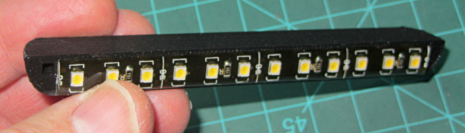
Mary’s Sears Kenmore Model 158 sewing machine arm has a flat rear surface and a plastic plate on the front, so double-sided adhesive foam tape can hold a straight mount in place; we rejected putting strips under the arm to avoid snagging on the quilts as they pass by. So, with LEDs in hand, these are the mounts…
LED strip lights must have strain relief for their wires, as our Larval Engineer discovered the hard way on her longboard ground lighting project, and I wanted nice endcaps to avoid snagging on the fabric, so the general idea was a quarter-round rod with smooth endcaps and a hole to secure the wire. Some experiments showed that the acrylic (?) LED encapsulation directed the light downward, thus eliminating the need for a shade.
So, something like this will do for a first pass:
LED Strip Light Mount – bottom view
The overall dimensions for the LED mounts:
Length: N x 25 mm, plus endcap radii
Front-to-back width: 10 mm to allow for strip variation and 1 mm protection
Top-to-bottom height: 12 mm to fit double-sided foam sticky squares
Wire channels: 3 mm diameter or square cross-section
If there’s not enough light, I think a double-wide mount with two parallel LED strips would work.
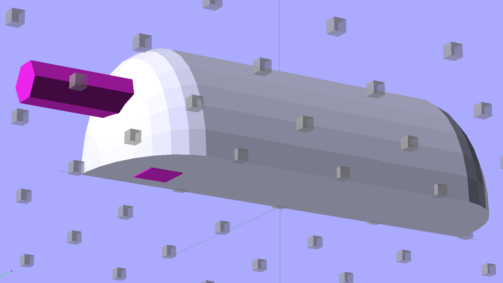
After a bit of screwing around with additive endcaps that produced catastrophically non-manifold solid models, I figured out the proper subtractive way to build the mounts: the endcaps actually define the overall shape of the mount.
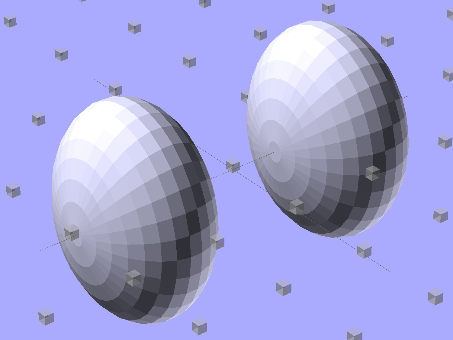
Start by placing a pair of spheroids, with radii matching the strip dimensions, so that their outer poles match the desired overall length:
Strip Light Mount – end cap spheroids – whole
The north/south poles must face outward, so that the equal-angle facets along the equators match up with what will become the mount body: rotate the spheroids 90° around the Y axis. The centers lie at the ends of the LED segments; the model shown here has a single 25 mm segment.
Then hack off three quadrants:
Strip Light Mount – end cap spheroids
That leaves two orange-segment shapes that define the endcaps:
Strip Light Mount – end caps – shaped
Here’s the key step that took me far too long to figure out. Shrinkwrapping the endcaps with the hull() function finesses the problem of matching the body facets to the endcap facets:
Strip Light Mount – end caps – hull
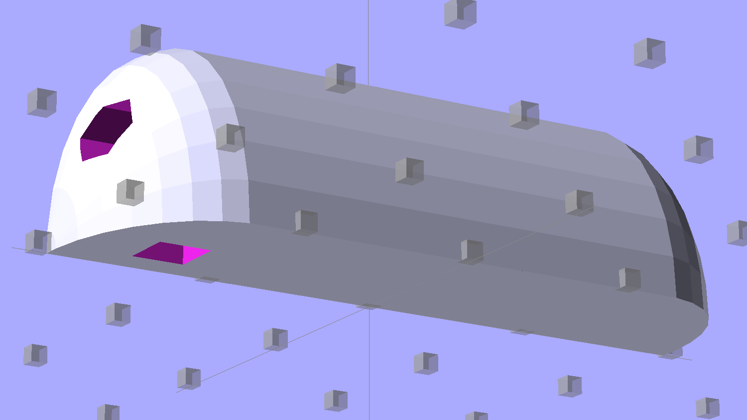
Model the wire channels as positive volumes that will be subtracted from the mount. The Channels layout shows both channels separated by a short distance:
Strip Light Mount – positive wire channels
The horizontal hexagons started as squares, but that looked hideous on the rounded endcaps.
Seen from the bottom, the mount starts like this:
Strip Light Mount – no wiring channels
Position and subtract a wire channel:
Strip Light Mount – visible wire channel
Which leaves the final solid model as a single, manifold object:
Strip Light Mount – complete
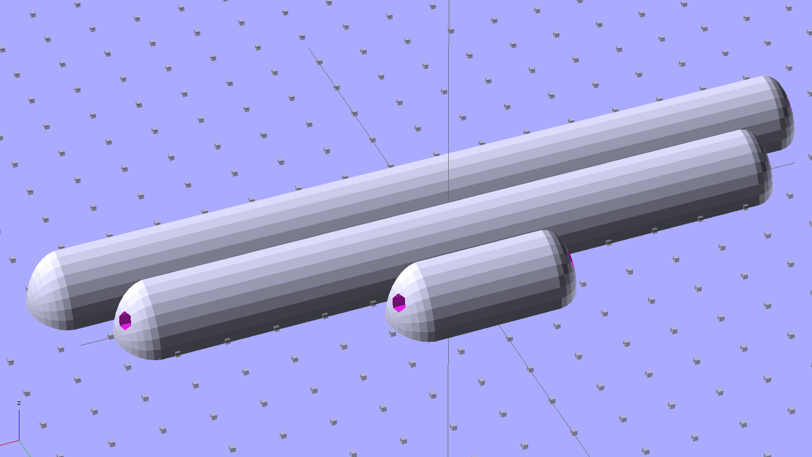
The module generating the mount takes three parameters: the number of LED segments and two string variables that determine whether to punch a channel in each endcap. Instantiate the module three times with suitable parameters to get a trio of LED mounts, all laid out for 3D printing:
Strip Light Mount – build layout
They built just exactly like those models would suggest; the M2 produces dependable results.
The OpenSCAD source code:
// LED Strip Lighting Brackets for Kenmore Model 158 Sewing Machine
// Ed Nisley - KE4ZNU - February 2014

Layout = "Strip";			// Build Show Channels Strip

//- Extrusion parameters must match reality!
//  Print with 2 shells and 3 solid layers

ThreadThick = 0.20;
ThreadWidth = 0.40;

HoleWindage = 0.2;			// extra clearance

Protrusion = 0.1;			// make holes end cleanly

AlignPinOD = 1.70;			// assembly alignment pins: filament dia

inch = 25.4;

function IntegerMultiple(Size,Unit) = Unit * ceil(Size / Unit);

//----------------------
// Dimensions

Segment = [25.0,10.0,3.0];		//  size of each LED segment

WireChannel = 3.0;				// wire routing channel

StripHeight = 12.0;				// sticky tape width
StripSides = 8*4;

DefaultLayout = [1,"Wire","NoWire"];

EndCap = [(2*WireChannel + 1.0),Segment[1],StripHeight];	// radii of end cap spheroid
EndCapSides = StripSides;

CapSpace = 2.0;						// build spacing for endcaps
BuildSpace = 1.5*Segment[1];		// spacing between objects on platform

//----------------------
// Useful routines

module PolyCyl(Dia,Height,ForceSides=0) {			// based on nophead's polyholes

  Sides = (ForceSides != 0) ? ForceSides : (ceil(Dia) + 2);

  FixDia = Dia / cos(180/Sides);

  cylinder(r=(FixDia + HoleWindage)/2,
           h=Height,
           $fn=Sides);
}

module ShowPegGrid(Space = 10.0,Size = 1.0) {

  RangeX = floor(100 / Space);
  RangeY = floor(125 / Space);

	for (x=[-RangeX:RangeX])
	  for (y=[-RangeY:RangeY])
		translate([x*Space,y*Space,Size/2])
		  %cube(Size,center=true);

}

//-- The negative space used to thread wires into the endcap

module MakeWireChannel(Which = "Left") {

	HalfSpace = EndCap[0] * ((Which == "Left") ? 1 : -1);

	render(convexity=2)
	translate([0,EndCap[1]/3,0])
		intersection() {
			union() {
				cube([2*WireChannel,WireChannel,EndCap[2]],center=true);
				translate([-2*EndCap[0],0,EndCap[2]/2])
					rotate([0,90,0]) rotate(180/6)
						PolyCyl(WireChannel,4*EndCap[0],6);
			}
			translate([HalfSpace,0,(EndCap[2] - Protrusion)]) {
				cube(2*EndCap,center=true);
			}
		}
}

//-- The whole strip, minus wiring channels

module MakeStrip(Layout = DefaultLayout) {

	BarLength = Layout[0] * Segment[0];				// central bar length

	hull()
		difference() {
			for (x = [-1,1])						// endcaps as spheroids
				translate([x*BarLength/2,0,0])
					resize(2*EndCap) rotate([0,90,0]) sphere(1.0,$fn=EndCapSides);
			translate([0,0,-EndCap[2]])
				cube([2*BarLength,3*EndCap[1],2*EndCap[2]],center=true);
			translate([0,-EndCap[1],0])
				cube([2*BarLength,2*EndCap[1],3*EndCap[2]],center=true);
		}

}

//-- Cut wiring channels out of strip

module MakeMount(Layout = DefaultLayout) {

	BarLength = Layout[0] * Segment[0];

	difference() {
		MakeStrip(Layout);
		if (Layout[1] == "Wire")
			translate([BarLength/2,0,0])
				MakeWireChannel("Left");
		if (Layout[2] == "Wire")
			translate([-BarLength/2,0,0])
				MakeWireChannel("Right");
	}
}

//- Build it

ShowPegGrid();

if (Layout == "Channels") {
	translate([ EndCap[0],0,0]) MakeWireChannel("Left");
	translate([-EndCap[0],0,0]) MakeWireChannel("Right");
}

if (Layout == "Strip") {
	MakeStrip(DefaultLayout);
}

if (Layout == "Show") {
	MakeMount(DefaultLayout);
}

if (Layout == "Build") {

	translate([0,BuildSpace,0]) MakeMount([1,"Wire","Wire"]);		// rear left side, vertical
	translate([0,0,0]) MakeMount([5,"Wire","NoWire"]);				// rear top, across arm
	translate([0,-BuildSpace,0]) MakeMount([6,"NoWire","Wire"]);	// front top, across arm
}
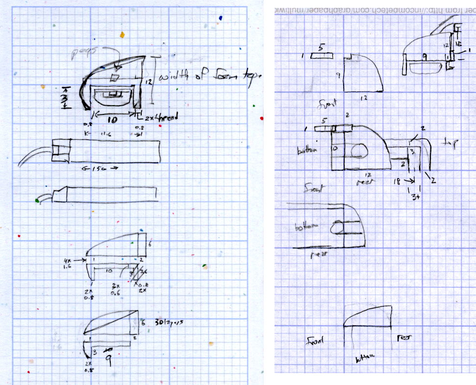
The original design doodles, which bear a vague resemblance to the final mounts:
LED Strip Light Mounts – Original Design Sketches
The little snood coming out of the top would hide a wire going through a hole drilled in the capital-S of “Sears” on the front panel, but I came to my senses long before implementing that idea…