Ed Nisley's Blog: Shop notes, electronics, firmware, machinery, 3D printing, laser cuttery, and curiosities. Contents: 100% human thinking, 0% AI slop.
Category: Software
General-purpose computers doing something specific
The Token Windows box (which runs the few programs that don’t get along with Linux) doesn’t get a lot of attention, but a recent update changed their stylin’ graphic CPU meter to something a bit less, mmm, smooth:
Although the TOM286 conversion won’t need any fancy firmware, I forked Marlin’s Github repository and created a TOM286 branch based on the Marlin_v1 branch for the Azteeg X3 modifications; in theory, we can blend in future Marlin updates without too much hassle.
The Pronterface serial port tops out at 115200, so that’s a mandatory change right up front. [grin]
Marlin has a motherboard definition for an Azteeg X3 (type 67), but without the optional thermocouple inputs. I added motherboard 671, following the lead of the Megatronics board definitions (types 70, 701, and 702). In addition to the changes below, any test for motherboard 67 now includes 671, as the other pins and suchlike (should) be the same.
Motherboard 671 selects new pin definitions for the temperature inputs in pins.h:
  #if MOTHERBOARD == 671
	#define TEMP_0_PIN         11   // TC1 on shield
	#define TEMP_1_PIN          4   // TC2 on shield
	#define TEMP_2_PIN         13   // T0 thermistor on Azteeg X3 motherboard
  #else
    #define TEMP_0_PIN         13   // ANALOG NUMBERING
    #define TEMP_1_PIN         15   // ANALOG NUMBERING
    #define TEMP_2_PIN         -1   // ANALOG NUMBERING
#endif
There’s now a TCOUPLE_AMP_TYPE definition in Configuration.h to select AD595 or AD849x thermocouple interfaces:
// Thermocouple sensor amplifier type
//  0 = AD595 gain = 10 mV/C
//  1 = AD849[4567] gain = 5 mV/C

#define TCOUPLE_AMP_TYPE 1
That picks the proper offset and gain definitions in Configuration_adv.h:
// The AD849[4567] has 5 mv/C gain, half that of the AD595, and requires _GAIN = 2

#if TCOUPLE_AMP_TYPE == 1
  #define TEMP_SENSOR_AD595_OFFSET 0.0
  #define TEMP_SENSOR_AD595_GAIN   2.0
#else
  #define TEMP_SENSOR_AD595_OFFSET 0.0
  #define TEMP_SENSOR_AD595_GAIN   1.0
#endif
With those in hand, these temperature sensor selections in Configuration.h will work:
I tweaked the temperature limits and preheat settings; the absolute minimum temperatures are now 10 °C, although I have not verified that a disconnected thermocouple or thermistor will actually trip that limit.
Given the completely arbitrary stepper motor wiring connections, I set all the direction inversions to false and then swapped wires to make the motors turn in the proper direction.
I enabled EEPROM_SETTINGS, but haven’t verified that values can actually store and recall themselves.
The XYZ=0 origin is in the middle of the platform, just where I like it, but that will require some fine tuning:
I think it’s possible to use the Z_SAFE_HOMING position to force Z-minimum homing on the platform height switch I built for the original firmware, but that operation also seems to be tied in with the three-point auto-leveling firmware and rotating switch assembly. Right now, the firmware homes to the Z-max switch as a stock Thing-O-Matic should, but I’ve never liked that arrangement; don’t start with me, you know how I get.
I backed the speeds and accelerations down from the values I’d been using, mostly because the driver hardware and currents are different:
// Computing steps/mm
// for XY = (motor steps/rev * microstepping) / (pulley teeth * tooth pitch)
// for  Z = (motor steps/rev * microstepping) / (screw lead) // for  E = (motor steps/rev * microstepping) / (gear ratio * drive circumference) //  make sure ratios use floating point to avoid integer division!
#define DEFAULT_AXIS_STEPS_PER_UNIT   {(200*16)/(17*2.0), (200*16)/(17*2.0), (200*8)/8.0, (200*4)/((7*30.23)/51)}
#define DEFAULT_MAX_FEEDRATE          {5000/60, 5000/60, 1500/60, 4000/60}    // (mm/sec)
#define DEFAULT_MAX_ACCELERATION      {5000, 2500, 1000, 250}    // X, Y, Z, E maximum start speed for accelerated moves. E default values are good for skeinforge 40+, for older versions raise them a lot.

#define DEFAULT_ACCELERATION          10000   // X, Y, Z and E max acceleration in mm/s^2 for printing moves
#define DEFAULT_RETRACT_ACCELERATION  10000   // X, Y, Z and E max acceleration in mm/s^2 for retracts
I’m not sure how to calculate the “jerk” settings, but taken as the maximum un-accelerated speed, these seem conservative:
// The speed change that does not require acceleration (i.e. the software might assume it can be done instantaneously)
#define DEFAULT_XYJERK                25    // (mm/sec)
#define DEFAULT_ZJERK                 5    // (mm/sec)
#define DEFAULT_EJERK                 5     // (mm/sec)
More tuning is in order; that should at least start it up.
The backup scripts running on Mary’s folks’ PC kvetched on each backup:
WARNING: Some files and/or directories in /home/ only transferred partially during rsync operation

WARNING: /usr/bin/rsnapshot daily: completed, but with some warnings
Poking around showed that the problem came from the .gvfs “directory” tucked into each home directory, which produced this unenlightening ls -al result:
d????????? ? ? ? ? ? .gvfs
Come to find out that it’s an old problem with mysterious causes that should be fixed by now; evidently I triggered it by installing basic Ubuntu-with-Unity and then installing the Xbubuntu desktop. Or something like that.
Anyhow, the solution workaround involves an rsnapshot configuration entry that bypasses that directory:
While walking from the Metropolitan Museum of Art to Grand Central on a frigid post-Christmas December evening, we encountered this storefront display:
Santa Ride – car
A closer look at the monitor in the background:
Santa Ride – crash report
Hmmm. Bit of a surprise: not a Windows box.
After walking two miles along Madison Avenue, I didn’t see one single item in the store windows that I’d buy, even in the after-Christmas discount season. Mary wasn’t enthralled by a pair of diamond-encrusted emerald earrings the size of my thumbs, either, which is likely a Good Thing.
We stopped in the Ugg Boot Store, both to warm up and so I’d know what all the spammers have been hawking…
That image has desaturated red to suppress the camera’s red burnout. It looks better in the realm of pure math:
Planetary Gear Bearing – Kurled – solid model
Reducing the tolerance parameter to 0.4 produced a surprisingly rigid, yet freely turning, bearing that required no cleanup: it popped off the plate ready to roll!
The heavy lifting in the OpenSCAD source code remains emmitt’s work. I replaced the outer cylinder with a knurl and simplified his monogram to stand out better amid the diamonds. This is the affected section:
This resembles the 32 GB Micro SD card checkout, with the exception that, for some unknown reason, the available space doesn’t match up with the actual space occupied by the file. It also turns out that rsync deletes the incomplete file, rather than leaving a stub, which makes perfect sense, but was still a bit disappointing after two hours.
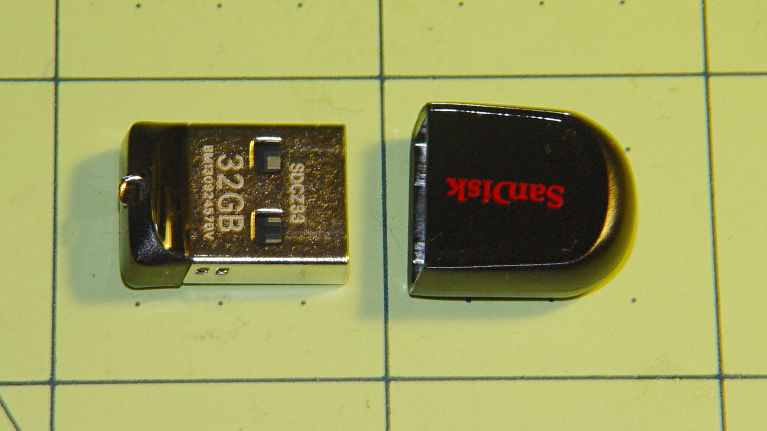
I had two identical Sandisk Cruzer Fit Flash Drives, one of which appears here:
32 GB Sandisk USB Flash Drive
Those squares are an inch on a side, so it’s a bit larger than the Micro SD card. Adding a lanyard loop on the plastic cap or a string between cap and drive seems like a great idea, because that little thing is certain to get lost.
The snippets here represent a compendium of Things Done that happened over the course of two days; I didn’t save all the logs. The process started with the same 32 GB file of entropy I used for the Micro SD card:
df -B1 /mnt/part2
Filesystem       1B-blocks      Used   Available Use% Mounted on
/dev/sdc1      31512350720 180424704 31331926016   1% /mnt/part2
-----------------------
time rsync --progress /mnt/part/Testdata/Testdata.bin /mnt/part2
Testdata.bin
 31298191360  99%   14.18kB/s    0:39:38
rsync: writefd_unbuffered failed to write 4 bytes to socket [sender]: Broken pipe (32)
rsync: write failed on "/mnt/part2/Testdata.bin": No space left on device (28)
rsync error: error in file IO (code 11) at receiver.c(322) [receiver=3.0.9]
rsync: connection unexpectedly closed (28 bytes received so far) [sender]
rsync error: error in rsync protocol data stream (code 12) at io.c(605) [sender=3.0.9]

real	126m20.505s
user	3m6.393s
sys	2m17.492s
-----------------------
time dd bs=8K count=20000000 if=/mnt/part/Testdata/Testdata.bin of=/mnt/part2/Test1.bin
dd: writing ‘/mnt/part2/Test1.bin’: No space left on device
3820963+0 records in
3820962+0 records out
31301320704 bytes (31 GB) copied, 7455.97 s, 4.2 MB/s

real	124m15.970s
user	0m1.607s
sys	1m17.546s
-----------------------
truncate -s 31301320704 /mnt/part/Testdata/Testdata.bin
-----------------------
ll /mnt/part/Testdata/Testdata.bin
-rw-r--r-- 1 ed ed 31301320704 Dec 24 18:13 /mnt/part/Testdata/Testdata.bin
-----------------------
time diff /mnt/part/Testdata/Testdata.bin /mnt/part3/Test1.bin

real	26m37.081s
user	0m4.400s
sys	0m52.723s
Notice that the write speed runs around 4 MB/s, which is a lot slower than you might expect from a USB 2.0 device; as with a hard drive, the interface doesn’t limit the throughput! The read speed, on the other paw, trots along at about 20 MB/s.
One of these will go to Mary’s folks as an online daily backup device; their PC will soon run a version of the rsnapshot scripts that back up our basement file server. It’s not off-site backup and it’s not proof against catastrophic hardware failure, but it should be good enough.
Mary’s compadres sometimes send her pictures of garden vegetables and quilting projects. Those pictures usually pass through Microsoft Outlook (or its ilk) and emerge in winmail.dat files that aren’t particularly useful in a Linux context. That page gives a good overview of the problem and how to resolve it; I’m just documenting the process here, so I can find it again.
Start by installing both tnef and convmv. I think the latter isn’t needed in our situation, because most folks use flat ASCII file names that come through just fine.
Save the attachment in, say /tmp and unleash tnef on it:
cd /tmp
tnef --file=winmail.dat
That unpacks all the attachments into /tmp, where one may have one’s way with them.
It’s not worth my effort to bolt that into the email programs and then maintain that mess across updates, so we’ll do it by hand as needed.
Microsoft certainly had a good reason for inventing Yet Another Encapsulation Format, although I wonder why good old ZIP wouldn’t have worked nearly as well…