Ed Nisley's Blog: Shop notes, electronics, firmware, machinery, 3D printing, laser cuttery, and curiosities. Contents: 100% human thinking, 0% AI slop.
Category: Software
General-purpose computers doing something specific
Quick summary: the current Linux startup machinery Runs All The Things! in parallel, leaving you to figure out all the interdependencies and update all the script files to match your requirements. Mostly, the distro maintainers figure all that, but if you have essential files mounted as NFS shares, then you can will reach a login screen before the mount process completes.
Having wrestled with this problem for a while, I think I’ve doped out the right way to coerce the Upstart Pachinko Machine to converge on a workable login.
The solution is to fire off a unique signal after the NFS mount command, then force the display manager to wait until it receives that signal, rather than depend on happenstance as I did before. The mounts occur in /etc/init/local.conf, which now looks like this:
description "Stuff that should be in /etc/rc.local"
author "Ed Nisley - KE4ZNU"

start on (local-filesystems and net-device-up IFACE=em1)
stop on shutdown

emits nfs-mounted

script

logger Starting local init...

logger Mounting NFS filesystems
mount /mnt/bulkdata
mount /mnt/userfiles
mount /mnt/diskimages
mount /mnt/music
initctl emit nfs-mounted
logger Ending local init

end script
The start condition ensures that this code won’t run until the wired LAN is up; note that what was once eth0 is now em1. Then, after the mounts happen, initctl fires the nfs-mounted signal.
The modification to /etc/init/lightdm.conf script consists of one additional line to wait for that signal:
start on ((filesystem
           and runlevel [!06]
           and started dbus
           and plymouth-ready
           and nfs-mounted)
          or runlevel PREVLEVEL=S)

stop on runlevel [016]

emits login-session-start
emits desktop-session-start
emits desktop-shutdown
I’m not convinced lightdm.conf is the right spot to jam a stick in the gears, but it seems to be the least-awful alternative. The login-session-start signal doesn’t appear in any file in that subdirectory and I have no idea where else to look.
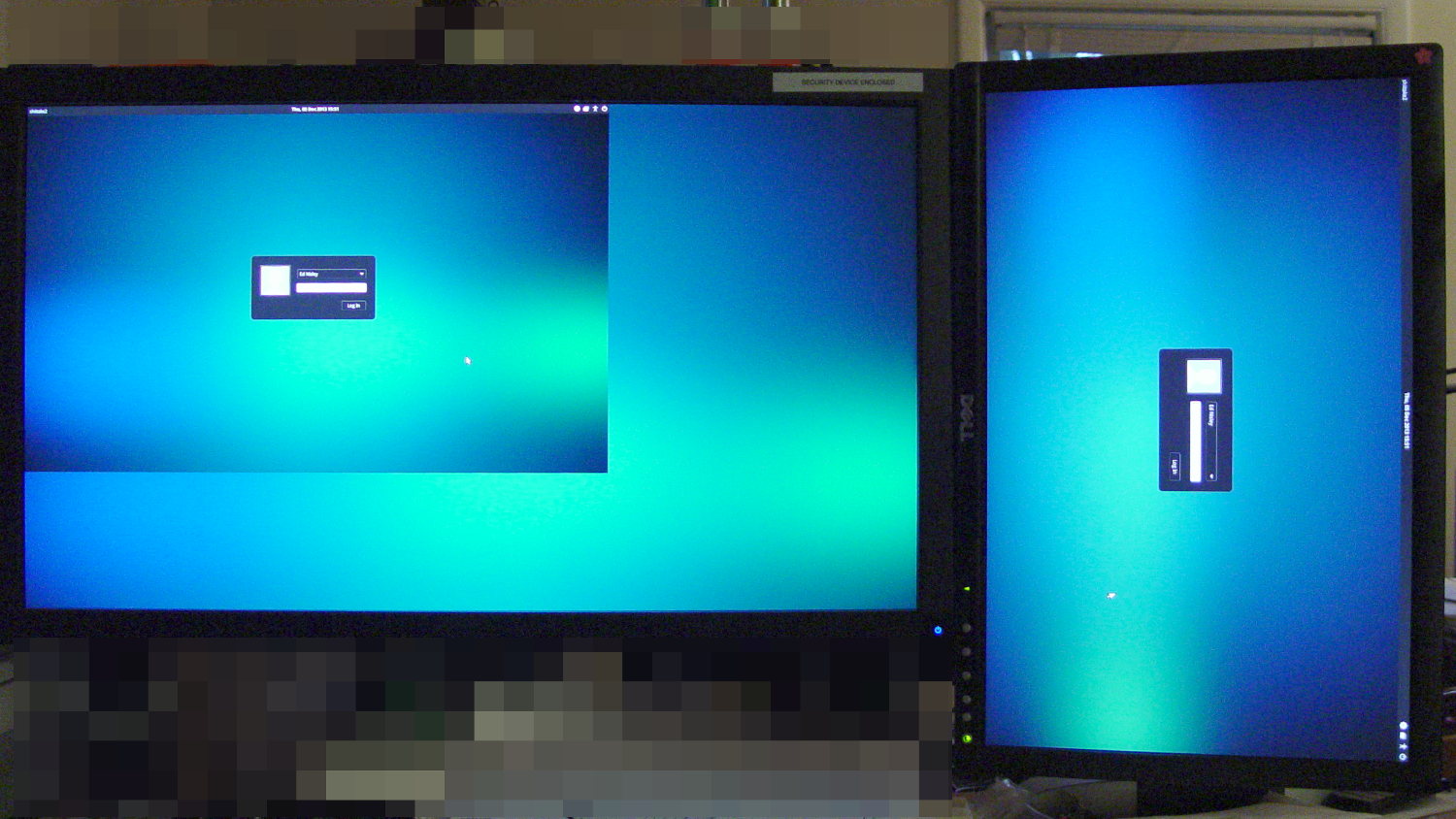
Anyhow, the greeter screen now shows a desktop background from the NFS mount, which I regard as A Good Sign:
Although the Optiplex 780 continues to chug along, some additional bringup notes for the new-to-me Optiplex 980 may be of future use. In no particular order, because that’s how it goes:
The OS is Xubuntu 13.10 in the 64-bit flavor, mostly for UI & infrastructure consistency with my other boxes. The Ubuntu project continues to diverge from consensus reality and the process of fighting down the Special Ubuntu Sauce seems increasingly difficult and less rewarding. This may be the last box I set up with Xubuntu, although I’m not sure what else to use; Arch requires more fiddly sysadmin-fu than I’m willing to allocate and Ubuntu-based distros like Mint seem to have all the disadvantage of Ubuntu plus the difficulties of splinter distros.
With two cores and HyperThreading turned on, it has enough moxie to run one instance of the GIMPS prime factoring code without crippling the UI. The estimated completion date for the current work is 9 July 2014, which should creep closer as the CPU sees more uptime. The previous crontab startup continues to work. It adds about 25 W to the baseline 50 W consumption.
Adobe has abandoned Adobe Reader for Linux and attempting to install the most recent version of 9.whatever produces a blizzard of warnings. I’ll try Okular and Evince, although both have problems with some PDFs that Reader handles with aplomb. Eliminating the security exposures in Reader should be a net win.
Okular gets its own devilspie2 rule that look a lot like the previous one for Adobe Reader:
if (string.find(get_window_name(),"Okular")) then
      unmaximize();
      set_window_geometry(0,0,1000,100);
      set_window_geometry(2561,0,1000,100)
      maximize();
end
This Optiplex 980 has two built-in video connectors (DisplayPort and VGA) that work with the Free Software drivers. After some fumbling around, the XFCE Display configuration utility positioned and rotated the landscape and portrait monitors as I wanted them. Running the 1680×1050 display with analog VGA signals produces a noticeably less crisp result, but it’s on the OK side of Good Enough.
The startup display / greeter doesn’t handle that configuration very well at all:
Xubuntu greeter – dual displays
The .xprofile file doesn’t need the xrandr hacks and includes the display names corresponding to the new video outputs:
setxkbmap -option terminate:ctrl_alt_bksp
#xrandr --output HDMI-0 --rotate left
#xrandr --dpi 100x100
xsetwacom --verbose set "Wacom Graphire3 6x8 stylus" MapToOutput "DP1"
xsetwacom --verbose set "Wacom Graphire3 6x8 eraser" MapToOutput "DP1"
Although I’m sure there’s a Better Way that’s now The Standard Method, just creating a simple /etc/X11/xorg.conf file (with nothing else!) swapped the Kensington Expert Mouse buttons:
Perhaps that should be in a file tucked in /usr/share/X11/, along with 50-wacom.conf, which I modified to swap the stylus buttons, which worked the last time:
The default audio stream goes through DisplayPort and comes out of the monitor’s audio jack, which took an embarassingly long time to discover. As nearly as I can tell, there is no way to enable the internal audio in addition to the DisplayPort channel; putzing with pavucontrol and alsamixer was unproductive.
The “indicator applet” sound control seems to be irrecoverably broken, for reasons having to do with the change from GTK2 to GTK3 (or something like that); the suggested workaround do not work for this system. Unfortunately, XFCE allows exactly one mixer applet in the panel, which will pose a problem with the USB headset I use for phone calls.
I think having the local.conf routine emit a unique signal after mounting the NFS shares, then having the lightdm.conf routine wait for that signal, might just do the trick. More research is needed.
Of course, a release or two ago the tried-and-true network interface names changed, for well and good reason, but … OK, I can use em1 instead of eth0, although I sure hope that’s not a random outcome.
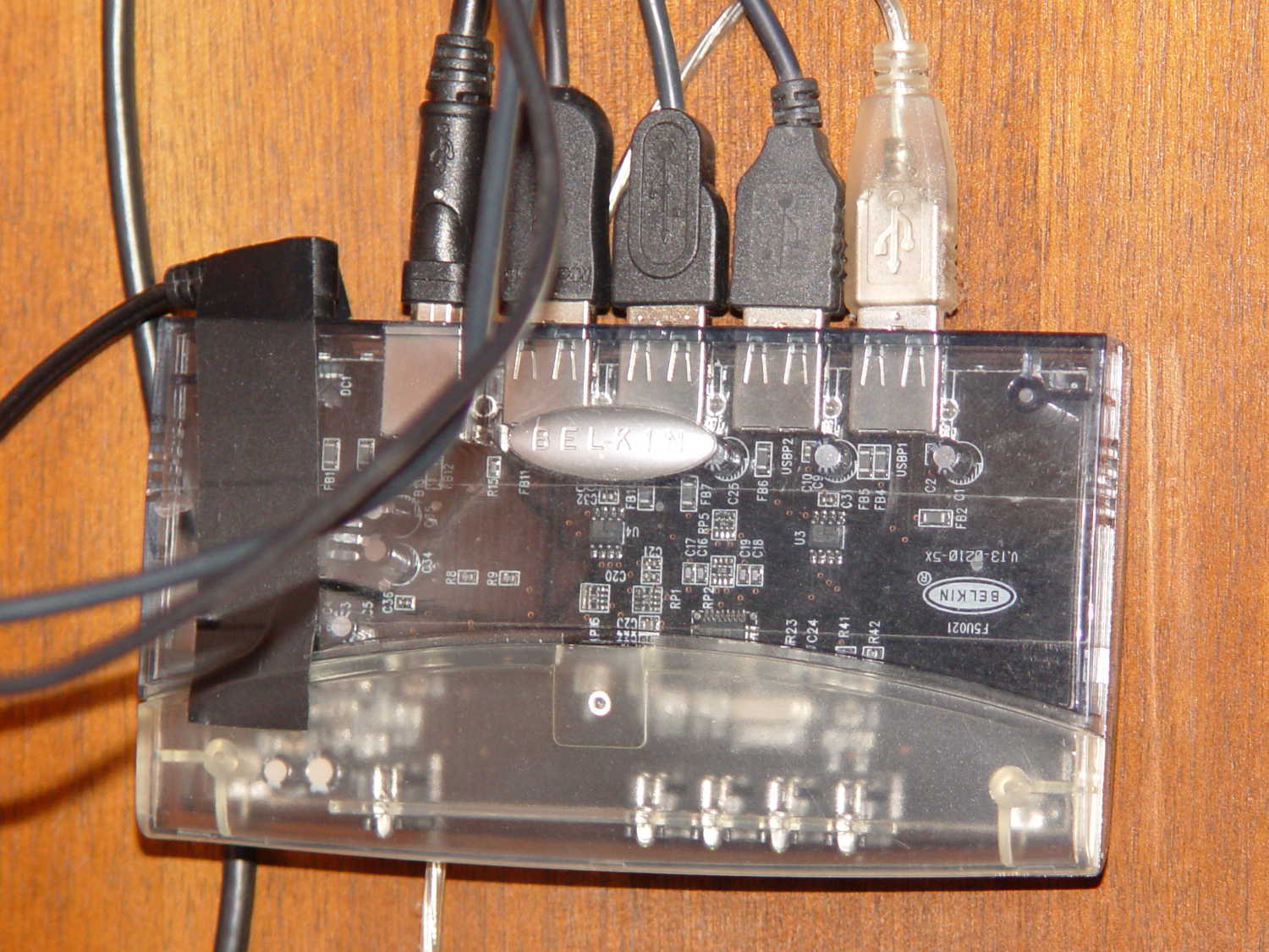
En passant, I discovered why the keyboard didn’t respond during boot: a crappy powered USB2 hub wasn’t working quite right. Swapping in an ancient Belkin powered USB hub solved that problem:
Belkin USB Hub – under desk
The hub concentrates the desktop peripherals (keyboard, two trackballs, and the tablet), so it doesn’t need high-speed throughput or responsiveness.
The general idea is to reduce the capacity of a 13 round Browning Hi-Power magazine to 10 rounds, in compliance with the NY Safe Act, using a number of possibly invalid assumptions. The new Firearms tag will produce earlier posts.
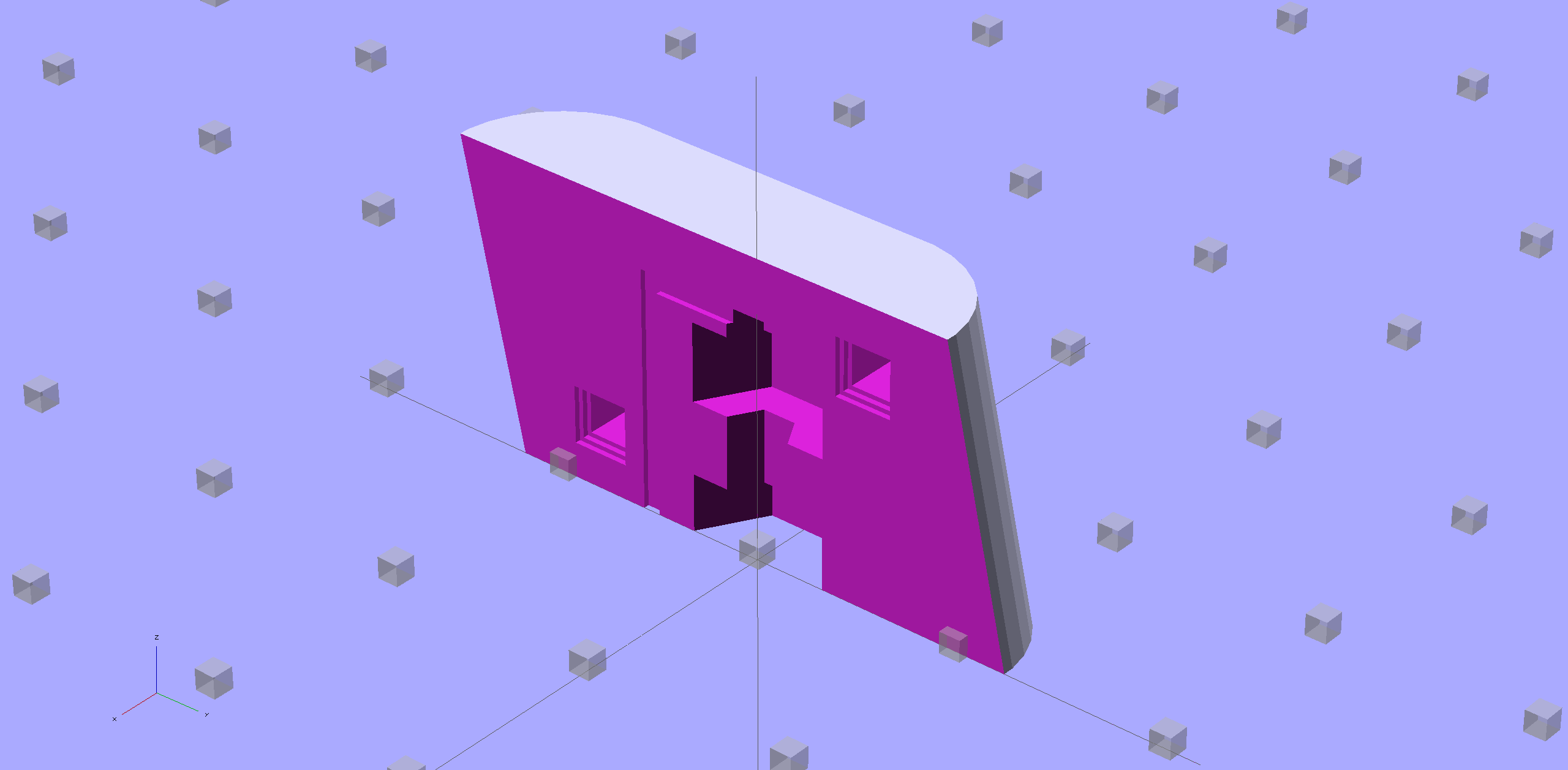
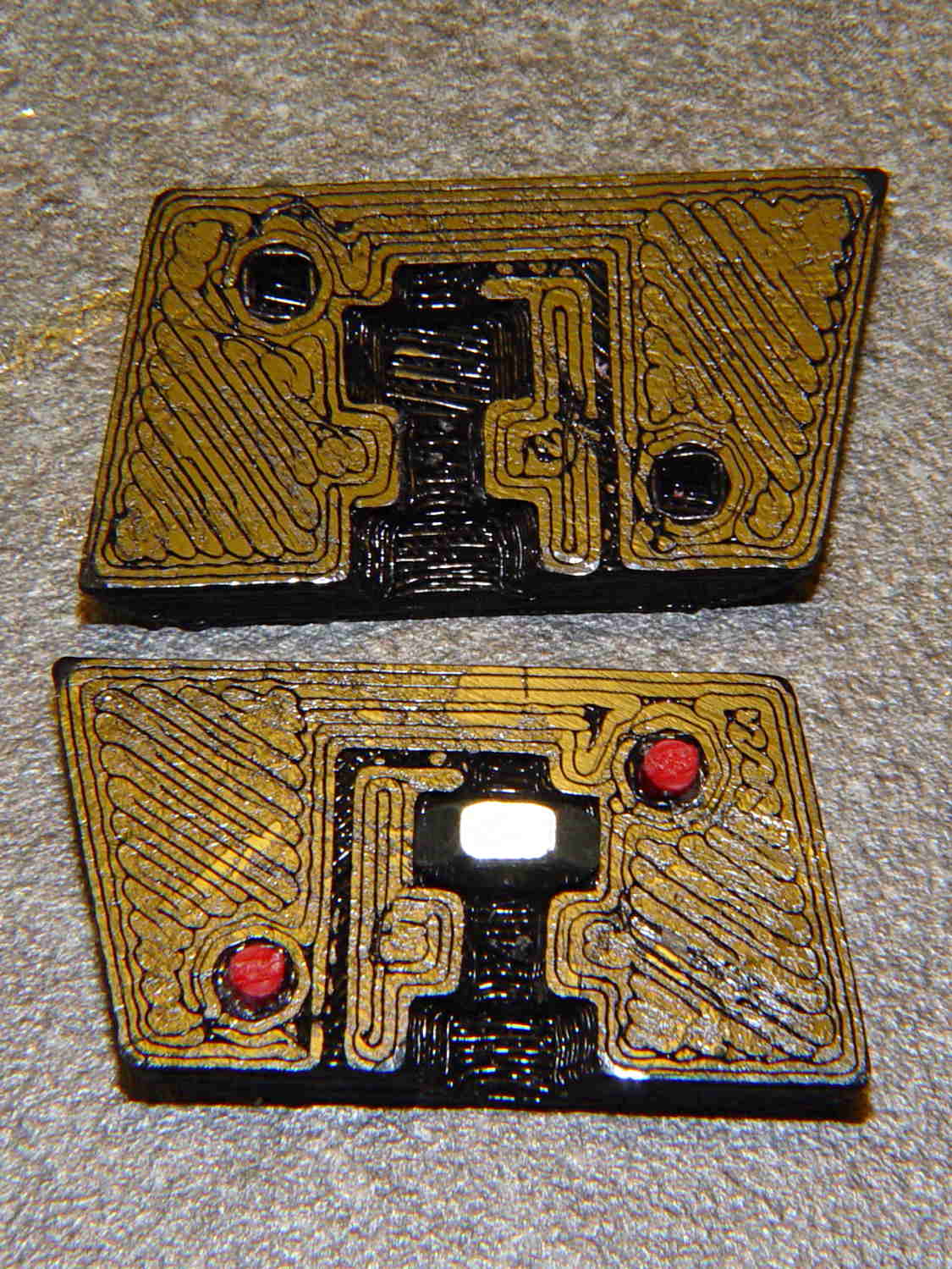
This early prototype tried out the sizes, shapes, and angles, using an M3x0.5 socket head cap screw:
The bottom nut trap locates the block on the inner floor plate by capturing the nut. It might need a bit more clearance or a chamfer to allow for brazing material around the nut flats; cleaning up the brazed nut with a file might also help.
The central trap holds a nut that anchors the block; the trap must be about 50% longer than the nut to allow for thread alignment, because the central hole is a loose tap fit.
That central nut probably isn’t needed, because you’d fill the central shaft with metal-loaded epoxy, which would form a perfectly serviceable, exactly form-fitting, and utterly non-removable “nut”. The vent from the end of the screw shaft releases air trapped behind the epoxy by the screw; if you don’t have a vent, then air pressure will force the epoxy out of the cavity.
If the epoxy “nut” is workable, then you can build it in a single piece printed vertically on the platform. Having a split version makes it easier to show off and, in truth, the cemented joint is about as strong as the rest of the object.
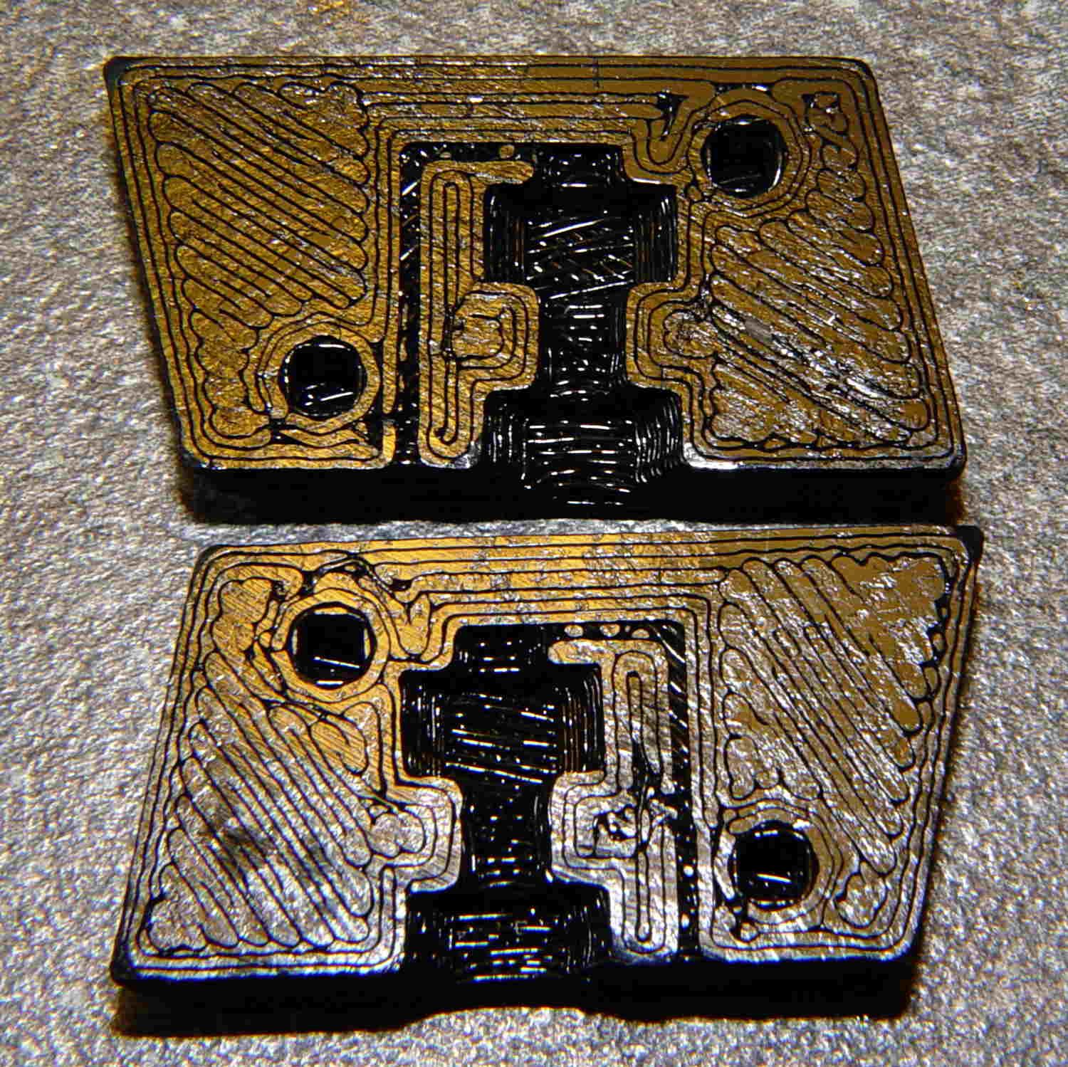
Hot off the M2 3D printer, it looks like this:
BHP magazine block – prototype nut trap – bare
A few threads droop into the air vent, so that channel should be larger. The overall plastic block may be porous enough to release the air pressure even without a vent.
With locating pins glued in place and a nut in the central trap:
BHP magazine block – prototype nut trap
Pretty much as I expected, it doesn’t quite fit in the magazine, because it doesn’t have clearance for the little tab on the inner floor plate that captures the spring.
One might argue that a plastic block isn’t “permanent”, but it’s definitely not “readily” removed:
PLA doesn’t dissolve in common solvents
It doesn’t actually melt and flow away at high temperatures
It’s protected by the spring and inner floor plate
It’s certainly strong enough to resist simple mechanical attacks
This is a start…
The OpenSCAD source code, replete with inadequacies:
// Browning Hi-Power Magazine Plug
// Ed Nisley KE4ZNU November 2013

Layout = "Show";			// Show Whole Pin Build

CrossSection = 1;			// -1, 0, 1 to select section side or none

Section = (Layout == "Build") ? 1 : CrossSection;		// for cross-section for build

//- Extrusion parameters must match reality!
//  Print with 2 shells and 3 solid layers

ThreadThick = 0.25;
ThreadWidth = 0.40;

HoleWindage = 0.2;

Protrusion = 0.1;			// make holes end cleanly

//----------------------
// Dimensions

Angle = 12.5;				// from vertical

EndDia = 10.3;				// an 11/32 inch drill fits
EndRadius = EndDia / 2;

Length = 24.0;				// front-to-back perpendicular to magazine shaft
Height = 14.0;				// bottom-to-top, parallel to magazine shaft
							//  14 = 10 round capacity
							//  28 = 7 round

RectLength = Length - EndDia;	// block length between end radii

ScrewOD = 3.0 - 0.5;		// bottom screw tapping diameter
ScrewLength = 11.0;
ScrewOffset = 0;			//   ... from centerline

NutOD = 5.5;				// hex nut dia across flats
NutThick = 2.4;				//  ... then add 50% for thread engagement & epoxy
NutOffset = 6.0;			//  ... base height from floor

VentWidth = 2*ThreadWidth;	// air vent from back of screw recess
VentDepth = 4*ThreadThick;

NumSides = 8*4;				// default cylinder sides

PinOD = 1.72;				// alignment pins
PinLength = 6.0;
PinInset = 0.9*EndRadius;	// from outside edges
echo(str("Alignment pin length: ",PinLength));

Offset = 5.0/2;				// from centerline for build layout

//----------------------
// Useful routines

// Locating pin hole with glue recess
//  Default length is two pin diameters on each side of the split

module LocatingPin(Dia=PinOD,Len=0.0) {

	PinLen = (Len != 0.0) ? Len : (4*Dia);

	translate([0,0,-ThreadThick])
		PolyCyl((Dia + 2*ThreadWidth),2*ThreadThick,4);

	translate([0,0,-2*ThreadThick])
		PolyCyl((Dia + 1*ThreadWidth),4*ThreadThick,4);

	translate([0,0,-(Len/2 + ThreadThick)])
		PolyCyl(Dia,(Len + 2*ThreadThick),4);

}

module PolyCyl(Dia,Height,ForceSides=0) {			// based on nophead's polyholes

  Sides = (ForceSides != 0) ? ForceSides : (ceil(Dia) + 2);

  FixDia = Dia / cos(180/Sides);

  cylinder(r=(FixDia + HoleWindage)/2,
           h=Height,
	   $fn=Sides);
}

module ShowPegGrid(Space = 10.0,Size = 1.0) {

  Range = floor(50 / Space);

	for (x=[-Range:Range])
	  for (y=[-Range:Range])
		translate([x*Space,y*Space,Size/2])
		  %cube(Size,center=true);

}

//----------------------
// Components

module Block(SectionSelect = 0) {

Delta = tan(Angle)*(Length/2);				// incremental length due to angle

CropHeight = Height*cos(Angle);				// block height perpendicular to base

echo(str("Perpendicular height: ",CropHeight));

	difference() {
		intersection() {
			rotate([Angle,0,0])
				difference() {
					translate([0,0,-Height/2])
						linear_extrude(height=2*Height,convexity=2) {
							for (i=[-1,1])
								translate([0,(i*RectLength/2),0])
									rotate(180/NumSides)
										circle(r=EndRadius/cos(180/NumSides),
												$fn=NumSides);
							square([EndDia,RectLength],center=true);
						}
					for (i=[-1,1])
						translate([0,
									(i*(Length/2 - PinInset)),
									(CropHeight/2 + i*(CropHeight/2 - PinInset))])
							rotate([0,90,0]) rotate(45-Angle)
								LocatingPin(PinOD,PinLength);
				}
			translate([0,0,CropHeight/2])
				cube([2*EndDia,3*Length,CropHeight],center=true);
		}
		translate([0,ScrewOffset,-Protrusion])		// screw
			rotate(180/6)
				PolyCyl(ScrewOD,(ScrewLength + Protrusion),6);

		translate([0,ScrewOffset,NutOffset])		// nut trap in center
			rotate(180/6)
				PolyCyl(NutOD,1.5*NutThick,6);

		translate([0,ScrewOffset,-Protrusion])		// nut clearance at base
			rotate(180/6)
				PolyCyl(NutOD,(1.1*NutThick + Protrusion),6);

		translate([0,-(ScrewOffset + NutOD),(ScrewLength - Protrusion)/2])	// air vent
			cube([VentDepth/2,VentWidth,(ScrewLength + Protrusion)],center=true);
		translate([0,(ScrewOffset - NutOD/2),(ScrewLength - VentWidth/2)])
			cube([VentDepth/2,NutOD,VentWidth],center=true);

		if (SectionSelect == 1)
			translate([EndDia,0,Height/2-Protrusion])
				cube([2*EndDia,3*Length,Height+2*Protrusion],center=true);
		else if (SectionSelect == -1)
			translate([-EndDia,0,Height/2-Protrusion])
				cube([2*EndDia,3*Length,Height+2*Protrusion],center=true);
	}

}

//-------------------
// Build it...

ShowPegGrid();

if (Layout == "Pin")
	LocatingPin(PinOD,PinLength);

if (Layout == "Show")
	Block(CrossSection);

if (Layout == "Whole")
	Block(0);

if (Layout ==  "Build") {
	translate([(Offset + Length/2),Height/2,0])
		rotate(90) rotate([0,-90,-Angle])
			Block(-1);
	translate([-(Offset + Length/2),Height/2,0])
		rotate(-90) rotate([0,90,Angle])
			Block(1);
}
We don’t drive the van nearly often enough (*) to keep the battery charged in cold weather, so I use a trickle charger to keep it alive between jaunts. While opening the hood one evening, I managed to twist the plastic fitting that anchors the hood prop rod beyond its limits and snapped the poor thing off, which left me holding the hood in one hand and the rod in the other.
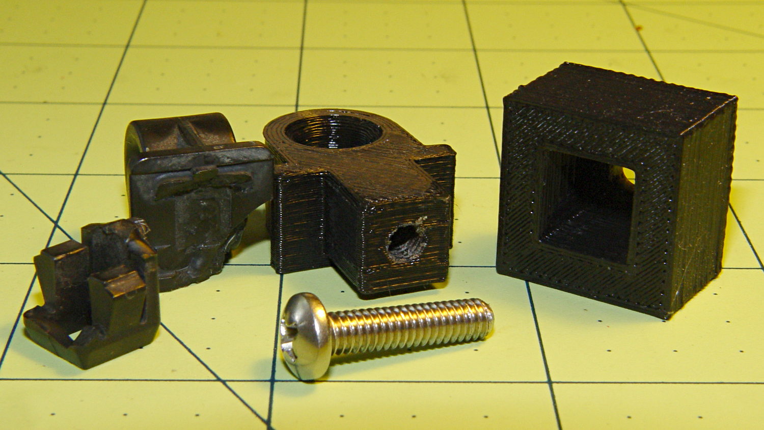
After extricating most of the fragments from under the van, I found that the OEM part had a hollow post that snapped into a square hole in the front bulkhead under the hood. The post had two keys and a pair of snap latches that held it in place, a design that seemed optimized for rapid assembly with no fiddly parts, but which depended on a few millimeters of plastic to restrain a meter of steel rod.
I made up a simple replacement with a solid square post and a square cap to clamp it against the bulkhead:
Toyota Sienna hood rod pivot – first version
The general idea is that the screw puts the entire post under compression, giving it less temptation to shear at the deck line when I twist the rod a bit too far out of line. That 8-32 screw seemed entirely adequate to the task; a 10-32 screw would take up too much of the post for my liking.
Alas, it turns out that underneath the bulkhead’s top flange lies a metal plate surrounding the headlight that’s so close to the hole that the big blocky cap wouldn’t fit. So I slimmed the cap down to three thread widths and tried again, only to discover that the plate came that close to the edge of square hole.
However, there was a gap between the bottom of the bulkhead and the top of the plate, so I introduced pivot and cap to Mr Belt Sander, removed enough plastic to let the cap slide into the gap, then discovered the 8-32 screw head was just slightly too large to let the screw align with the post.
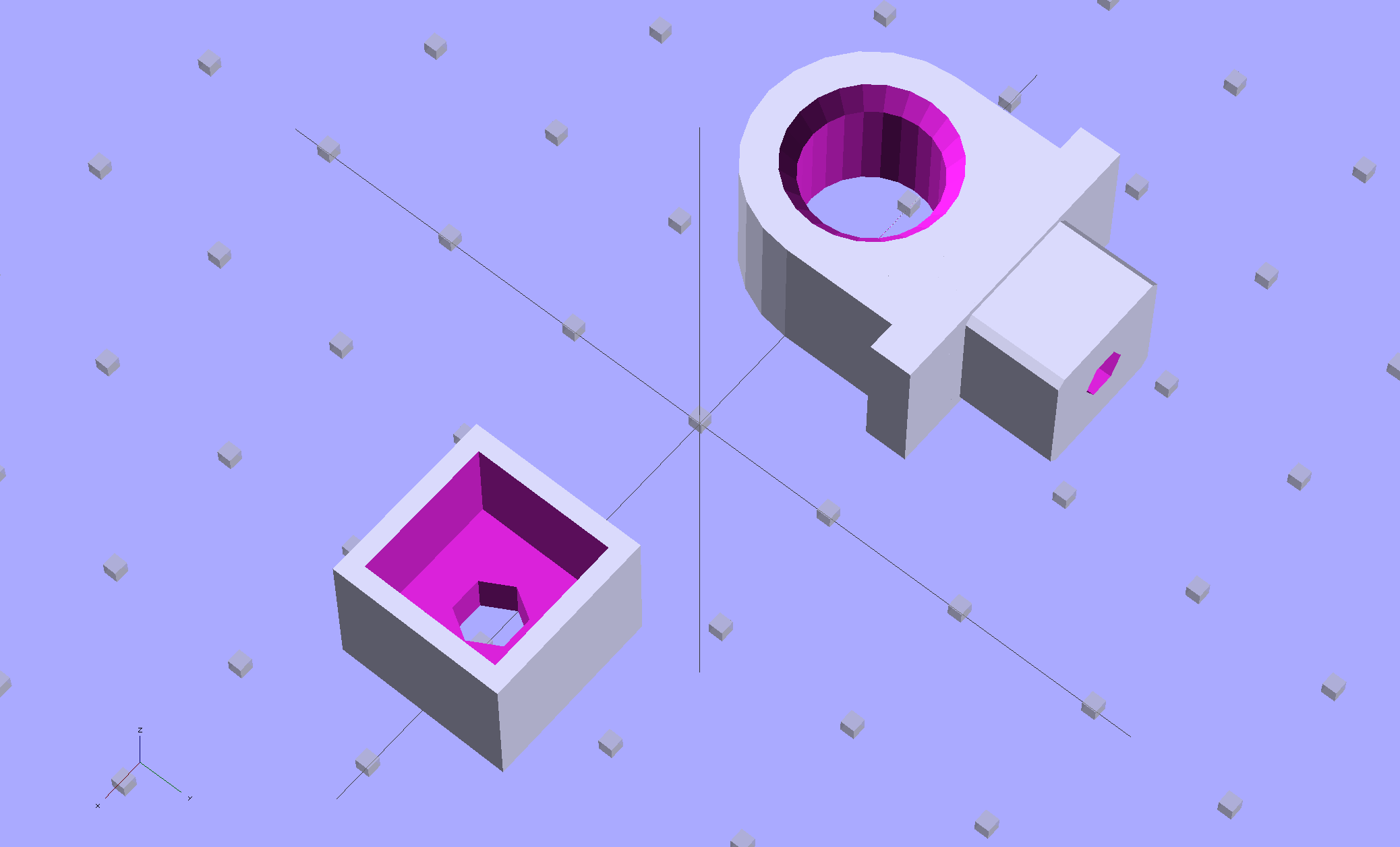
Another tweak to the model, based on actual measurements on the abused parts, produced the final version:
Toyota Sienna Hood Rod Pivot – solid model
The rod hole has a nice bevel, there’s no fragile neck between the rod hole and the base flange, the solid post lies flat on the platform for EZ building, and there’s a slight offset between the post and the flange that eliminates the need for support material. Printing it lying down orients the filament paths around the hole and base, making the part stronger in the direction it needs the most strength.
I think the cap walls could be slightly thicker, but we’ll see how long the thing lasts…
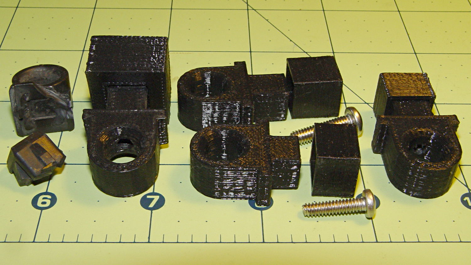
A group photo of all the versions, lined up from left to right, shows the broken OEM part, the first blocky attempt, the slimmed-down and too-long version to the rear, the shorter version that actually fit, and a backup part for when that one breaks:
Toyota Sienna hood rod pivot versions
The sanded-down part held the hood open while I took that group picture. Here’s what it looks like under load:
Toyota Sienna hood rod pivot – in place
The scrawls on the bulkhead just in front of the pivot remind me of fluid levels, torques, and suchlike. The stud sticking out to the rear is a headlight aiming screw mounted in the plate that caused so much hassle; you’d think I’d have noticed it before starting this adventure, but noooo…
For what it’s worth, that’s rapid prototyping in action: three (and a half) iterations in quick succession, each getting closer to a goal that you (well, I) can’t quite define, but will recognize when it appears. Took about three hours over the course of two days.
I loves me my M2 3D printer…
(*) Indeed, the tires often take three miles to warm up their flat spots due to sitting in the garage for a week…
While reducing the clutter atop the Electronics Workbench, I ran off four more probe flange reinforcements, just so I’m ready for the next crunch:
HP scope probe flange disks
They’re almost identical to the previous version, although I tweaked the taper to end slightly inside the cylindrical cup, thereby eliminating the coincident faces and leaving a minute rim that doesn’t matter:
HP Scope Probe Flange Repair – bottom
Given that I’ve had the ‘scope for nigh onto two decades and have only broken one probe flange, I think four reinforcements will be a lifetime supply: with any luck, the scope will blow a capacitor before I do.
The OpenSCAD source code:
// Tek Scope Probe Flange
// Ed Nisley KE4ZNU November 2013

//- Extrusion parameters must match reality!
//  Print with 2 shells and 3 solid layers

ThreadThick = 0.20;
ThreadWidth = 0.40;

HoleWindage = 0.2;

Protrusion = 0.1;            // make holes end cleanly

function IntegerMultiple(Size,Unit) = Unit * ceil(Size / Unit);

//----------------------
// Dimensions

FlangeOD = 16.0;
FlangeID = 8.75;
FlangeThick = IntegerMultiple(1.25,ThreadThick);

DiskOD = FlangeOD + 4*ThreadWidth;
DiskThick = FlangeThick + 4*ThreadThick;

NumSides = 8*4;

//----------------------
// Useful routines

module PolyCyl(Dia,Height,ForceSides=0) {            // based on nophead's polyholes

Sides = (ForceSides != 0) ? ForceSides : (ceil(Dia) + 2);

FixDia = Dia / cos(180/Sides);

cylinder(r=(FixDia + HoleWindage)/2,
h=Height,
$fn=Sides);
}

module ShowPegGrid(Space = 10.0,Size = 1.0) {

Range = floor(50 / Space);

for (x=[-Range:Range])
for (y=[-Range:Range])
translate([x*Space,y*Space,Size/2])
%cube(Size,center=true);

}

//----------------------
// Build it

ShowPegGrid();

difference() {
union() {
translate([0,0,2*ThreadThick])
cylinder(r=DiskOD/2,h=DiskThick,$fn=NumSides);    // cylinder around flange

cylinder(r1=(DiskOD - 2*ThreadWidth)/2,                // flange reinforcing plate
r2=DiskOD/2,
h=(2*ThreadThick + Protrusion),
$fn=NumSides);
}
translate([0,0,(DiskThick - FlangeThick)])                // flange clearance
PolyCyl(FlangeOD,2*FlangeThick,NumSides);

translate([0,0,-DiskThick/2])                            // probe nose clearance
PolyCyl(FlangeID,2*DiskThick,NumSides);
}
As you might expect, changing the layer thickness to 0.1 mm = 100 μm dramatically improves the appearance of the dummy 9 mm Luger bullet on the left, compared to the 0.25 mm = 250 μm layers on the right:
Dummy 9 mm Luger cartridges – 0.1 mm layer – overview
The inside edge of the translucent skirt around the quartet measured 90 to 110 μm, so the layer height is spot on:
Dummy 9 mm Luger bullets – 0.1 mm layer – overhead on platform
That required no adjustments to the M2 at all; It Just Works. Admittedly, that’s with a custom platform and firm supports replacing the springs, plus better Z-axis homing, but the overall structure was fine to start with.
I used the same Slic3r settings as before, with the only change being the layer thickness. Letting it pick the layer width might produce better results, but a 0.35 mm nozzle won’t go much narrower than 0.40 mm anyway.
A closer look at the bullet show the thinner layers provide a better rendition of the stretched sphere forming the nose; it’s less pointy than the one assembled from thicker layers:
Dummy 9 mm Luger bullets – 0.1 mm layer – side
The nose closes better with thinner layers:
Dummy 9 mm Luger bullets – 0.1 mm layer – nose
None of that really matters for this application, but it’s a useful data point.
The downside is that printing with thinner layers requires more time: a single bullet (of 16) requires 2.2 minutes at 250 μm and (of 4) 9 minutes at 100 μm. The simple ratio of layer thicknesses predicts a factor of 2.5, not 4, but the skirt requires a larger fraction of the total time. The estimated time for a 4×4 array at 100 μm comes out at 5.2 minutes each, a factor of 2.4, which is close enough.
Although 100 μm certainly looks better, it doesn’t really improve anything for most of the blocky stuff I make…
That’s a snap cap on the left and a real 9 mm Luger cartridge on the right. The holes in the dummy brass indicate that they are absolutely, positively, unquestionably not loaded cartridges.
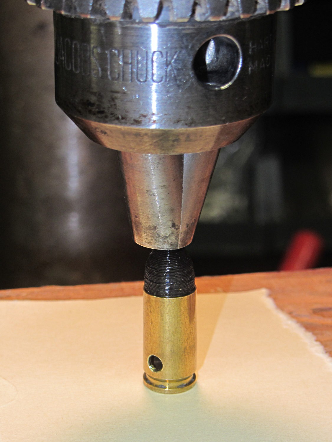
Start by drilling a 1/8 inch hole in the side of each unfired, primerless case:
Dummy 9 mm Luger – drilling case
I set up the chuck on the rotary table, thinking I might drill three holes in each cartridge, but came to my senses. It’s lined up by eye, flush with the end of the jaws, and the hole is just above the inside of the base.
The solid model has the same overall length and proportion as a 115 grain FMJ bullet, but doesn’t match the proper ogive or base diameter. Basically, I stretched a 9 mm sphere and stuck it atop a slightly tapered base cylinder:
Dummy 9 mm Luger bullet – solid model
For reasons I don’t profess to understand, the sphere has a slightly different diameter at its equator than the top of the cylinder, even though they’re both the same BulletOD diameter with the same number of faces. Fortunately, that didn’t affect the final results.
Print up a handful of the things:
Dummy 9 mm Luger bullets – on platform
The shadow from the flash makes the bases look slightly fatter than they really are.
Using a thinner layer would look better in this orientation. They’d definitely look better if they were split, printed with the long axis parallel to the plate, and glued together, as the grain would run lengthwise; I’m not sure there’s enough room for alignment pins, though.
At this diameter and number of faces, the M2 produces almost perfectly accurate dimensions, so the bullets press-fit just like you’d expect. They’re twisted into a dab of urethane glue inside the brass that foams just enough to hold them place.
Rather than use a real seating die, I deployed a closed chuck on the drill press. The trick is to set the depth stop to produce slightly too-long cartridges, then shim the platform without changing the stop and seat the bullet to the proper depth:
Dummy 9 mm Luger – seating bullet
The OAL tolerance for various 9 mm Luger cartridges seems to range from 1.08 inch to 1.17 inch, so anything in that range should be fine. I used 1.10 inch.
These are not intended for firing. You could fire them with just a primer (in a non-drilled case) and (maybe) not melt or shatter the plastic, but they’re slightly larger than the nominal 8.82 mm land diameter and won’t obturate or spin-stabilize worth diddly: expect short range and keyholing.
The sectional density is a whopping 0.008, should you keep track of such things: 0.47 gram = 7.2 grain. Note that the US small arms definition of sectional density has units of pound/inch2, not the pound/foot2 you’ll find right next to values computed using inches; the magic number 1/7000 just converts from grains to pounds. In the rest of the (metric) world, it’s entirely different.