Ed Nisley's Blog: Shop notes, electronics, firmware, machinery, 3D printing, laser cuttery, and curiosities. Contents: 100% human thinking, 0% AI slop.
The Dell Optiplex 9010 acting as a file server woke up dead after I plugged it in after returning from a road trip. Its ID sticker shows a manufacturing date almost exactly nine years ago and the problem was exactly what you might expect:
Optiplex CR2032
I’d never measured 100 mV on a CR2032 before.
Because the Optiplex runs headless in the basement, diagnosis required hauling it upstairs, booting it with a display & keyboard, whacking the date into the current decade, then resetting a few other vital bits.
The Huion tablet on my desk has its USB cable sticking straight out of the left side, whereupon it must loop around to burrow under the shelf under my monitor on its way to the port on the back of the PC case. The loop snagged on all the clutter atop the desk and I finally got around to Fixing That Problem:
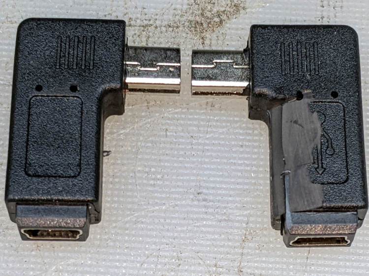
Which is a “left angle” adapter and which is a “right angle” adapter depends on which supplier you ask and how much you trust their descriptions / product photos, so you should get a set containing both: it’s the only way to be sure.
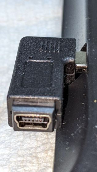
The one on the right (a “right angle”) shows a bit of carving, which came after the completely unsurprising discovery that the stylin’ curves on the side of the tablet collided with the rectangular adapter:
Huion tablet – misfit adapter
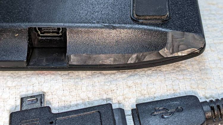
Some diligent X-Acto knife work carved away enough of both the adapter and the tablet case to snugly join them:
Huion tablet – plastic surgery
The hackery over on the far right fits around the USB cable’s molded connector. I simply cut away any parts that touched until the adapter seated firmly in the USB socket and the cable exited parallel to the edge.
Part of this involved not carving deeply enough into the adapter or cable connector to expose the internal wiring. I assumed the tablet didn’t have anything vital immediately inside that fancy curve, so that’s where I dug deepest.
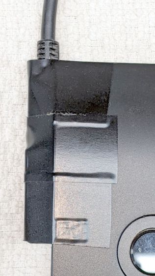
Stick adapter + cable to the tablet with good-quality electrical tape and now the cable points directly to where it should go.
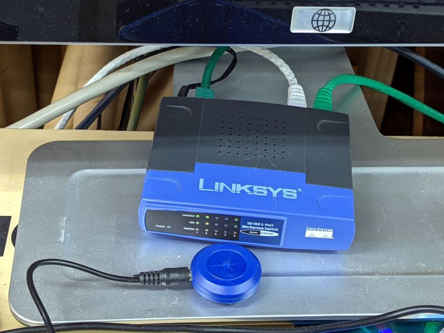
The CNC-3018XL and MPCNC machines each have a Raspberry Pi feeding G-Code into an Arduino clone controlling the stepper motors. The former grew a USB WiFi interface in place of its internal WiFi hardware when it seemed to have difficulty connecting to the house router, while the latter pretty much worked. Of late, however, I’ve been trying to reduce the number of WiFi devices cluttering the airwaves, with the result of wiring both machines to an old Ethernet switch from the Box o’ Network Stuff:
LinkSys Switch for CNC machines
The blue puck is the KVM button to select one of the machines for the keyboard / mouse / monitor on the bench.
One key point I generally screw up: the WiFi IP address cannot become the wired IP address without rebooting everything else on the network. Instead, just change the IP addresses and be done with it.
Collecting all the pieces in one place:
Disable the both internal WiFi hardware and Bluetooth in /boot/config.txt, thereby eliminating the need to force the WiFi down in /etc/rc.local:
For the first time in a loooong time I (had to) set up remote desktop sharing, starting from an existing SSH login through a single-port pinhole in an immutable router firewall.
The remote PC runs Xubuntu 20.4 LTS and I verified it already had x11vnc installed. If that’s not the case, make it so.
In order to share / control the desktop of a different user (hereinafter known as kay), I must SSH into that PC as kay. My SSH session uses public key authentication and kay has no need for outbound SSH, so just use my PC’s public key in kay‘s authorized_keys file. On the remote PC, where I am signed in as me:
cd ~
sudo mkdir /home/kay/.ssh        # kay does not have a public key
sudo cp .ssh/authorized_keys /home/kay/.ssh     # so just copy mine
sudo chown -R kay:kay /home/kay/.ssh     # transfer ownership
sudo chmod go-rwx /home/kay/.ssh     # set proper permissions
Installing Atkinson Hyperlegible reminded me to clear out the Noto font clutter in this (relatively nerecentw) Manjaro installation. Of course fonts now appear in slightly different locations with slightly different names, so this remains just a serving suggestion:
For unknown reasons, we now have two font cache updaters:
sudo fc-cache -v -f
sudo fc-cache-32 -v -f
Now font selection in, say, LibreOffice doesn’t involve paging through a myriad fonts in languages I cannot recognize, let alone read. Admittedly, Inconsolatadoes have more variations than I’ll ever use.
In mostly reverse chronological order, here are various commands I’ve puzzled out:
#xsetwacom --verbose set "HUION Huion Tablet stylus" MapToOutput "DP1-8"
xsetwacom --verbose set "HUION Huion Tablet stylus" MapToOutput "DP-1-8"
#xsetwacom --verbose set "HUION Huion Tablet Pen stylus" MapToOutput "DP-1"
#xsetwacom --verbose set "Wacom Graphire3 6x8 Pen stylus" MapToOutput "DP-1"
#xsetwacom --verbose set "Wacom Graphire3 6x8 Pen stylus" MapToOutput "HEAD-0"
#xsetwacom --verbose set "Wacom Graphire3 6x8 Pen eraser" MapToOutput "DP-1"
#xsetwacom --verbose set "Wacom Graphire3 6x8 Pen eraser" MapToOutput "HEAD-0"
Over the last two years, the display name changed from DP-1 to DP-1-8 to DP1-8, and back to DP-1-8. I grew accustomed to this with the Wacom tablet (HEAD-0‽)and now know where to look, but I still have no idea of the motivation.
Aaaand the tablet’s stylus name? The Wacom names were stable, but the Huion names apparently come from the Department of Redundancy Department.
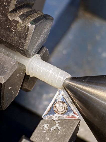
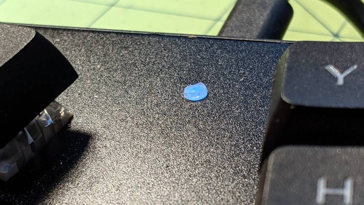
It stands slightly proud of the surface plate so I can extract it without dismantling the whole keyboard again:
Atreus keyboard – LED diffuser installed
I’ll eventually make a better-looking diffuser from a recently arrived translucent acrylic rod, but this will reduce the accumulation of fuzz inside the keyboard until the matching Round Tuit arrives.