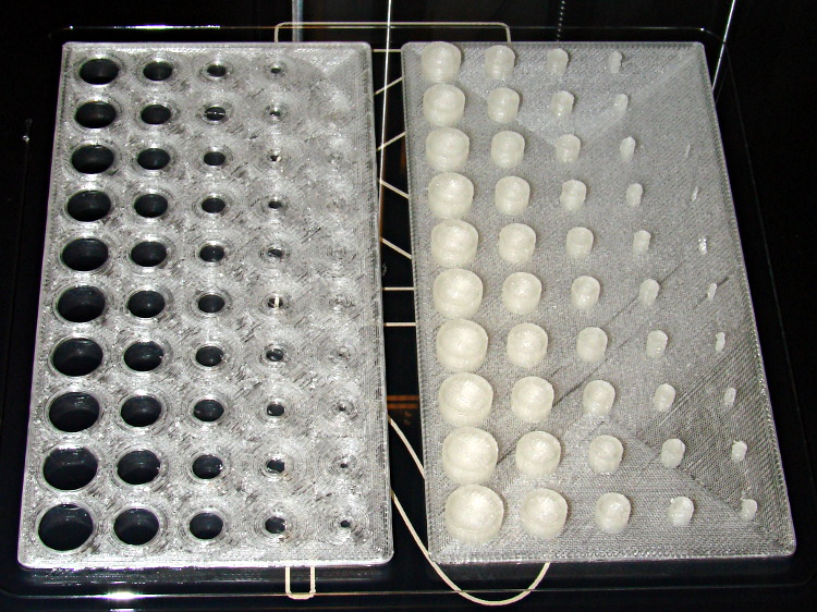
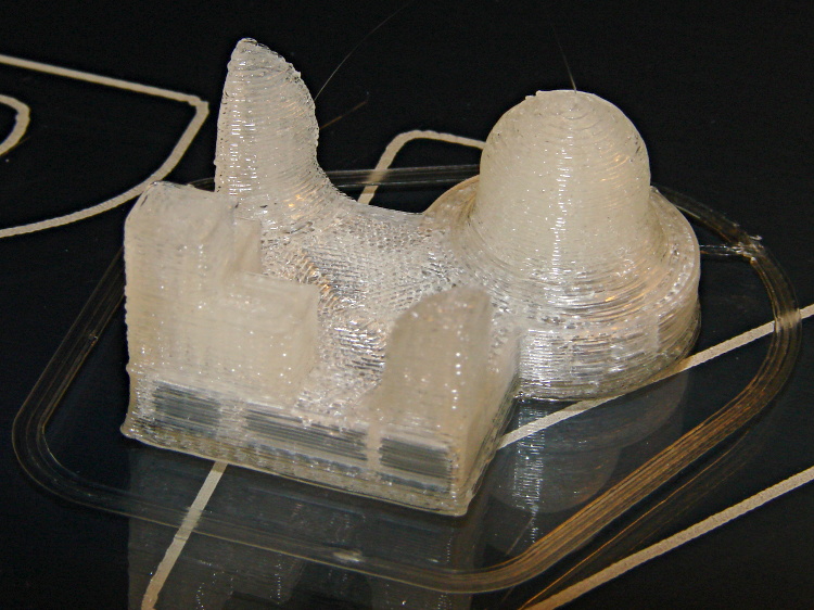
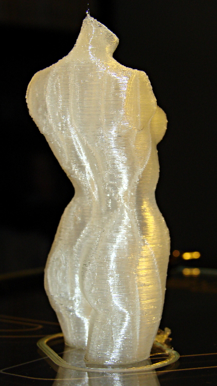
I redesigned those fins to fit 16 gram threaded CO2 cartridges in PLA on the M2:
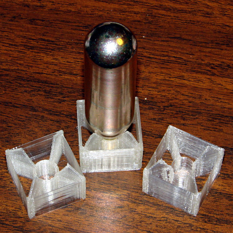
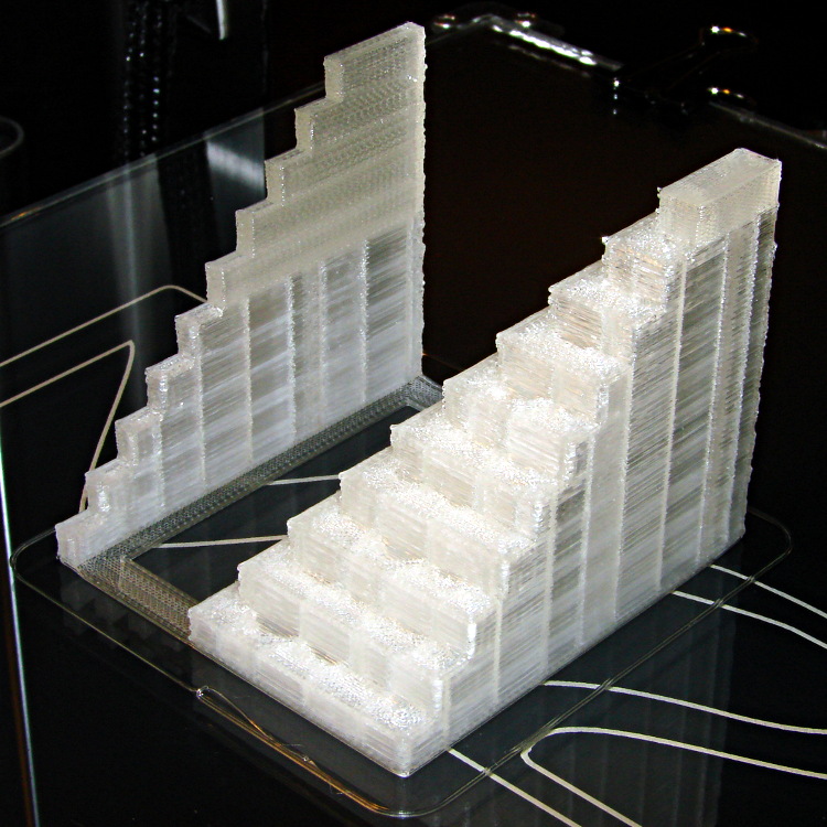
The original intent was to have both the square box and the internal X struts be exactly two threads wide, but the two fins on the sides show slic3r had some trouble doing that. I finally made them wide enough for a little fill, which produced the rather chunky version attached to the capsule.
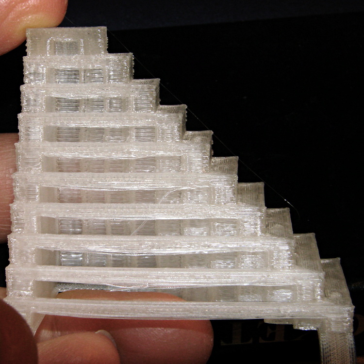
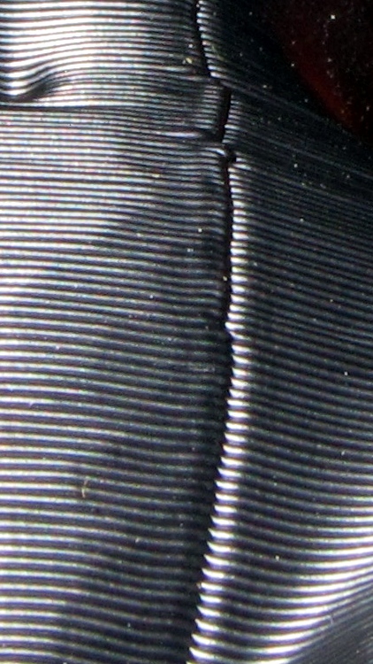
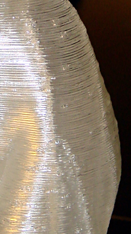
A closer look while printing shows the fin width:

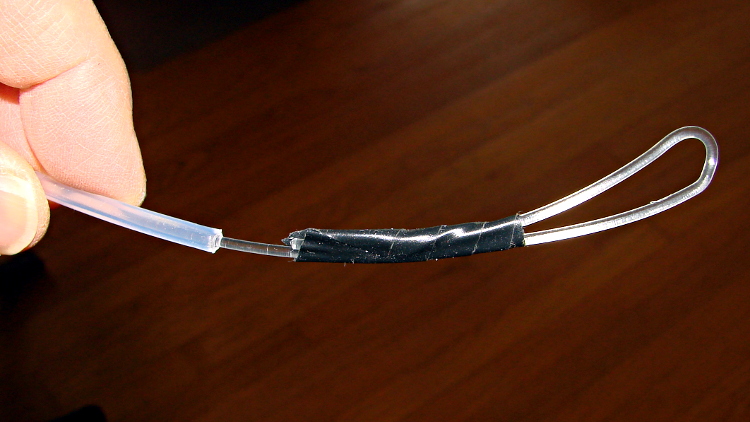
It was actually a present to go along with a box of the capsules, so I printed just one in a bit of a hurry. He probably couldn’t get them back across the border, but it’s the thought that counts, right?
The slic3r header:
; generated by Slic3r 0.9.8 on 2013-04-04 at 20:53:07

; layer_height = 0.25
; perimeters = 1
; top_solid_layers = 3
; bottom_solid_layers = 3
; fill_density = 0.10
; perimeter_speed = 100
; infill_speed = 200
; travel_speed = 500
; scale = 1
; nozzle_diameter = 0.35
; filament_diameter = 1.70
; extrusion_multiplier = 0.9
; perimeters extrusion width = 0.40mm
; infill extrusion width = 0.40mm
; first layer extrusion width = 0.39mm
The OpenSCAD source has dimensions for various capsules as commented-out cruft, so your mileage may vary:
// CO2 capsule tail fins
// Ed Nisley KE4ZNU - Apr 2013

Layout = "Build";            // Show Build FinBlock Cartridge Fit

//-------
//- Extrusion parameters must match reality!
//  Print with +0 shells and 3 solid layers

ThreadThick = 0.25;
ThreadWidth = 0.40;

HoleWindage = 0.2;

Protrusion = 0.1;            // make holes end cleanly

function IntegerMultiple(Size,Unit) = Unit * ceil(Size / Unit);

//-------
// Capsule dimensions

//- 12 gram capsule

/*
BodyDia = 18.70;
BodyRad = BodyDia/2;

BodyLength = 53.0;                        // between hemispherical endcap centers
BodyBaseLength = 21;                    // tip to endcap center

TipDia = 7.40;
TipRad = TipDia/2;
TipLength = IntegerMultiple(4.0,ThreadThick);

FilletLength = 5.0;                        // fillet between tip and cone
FilletTop = TipLength + FilletLength;

FilletBaseDia = 8.60;
FilletBaseRad= FilletBaseDia/2;
FilletTopDia = 9.5;
FilletTopRad = FilletTopDia/2;

ConeTop = 16.0;                            // tip to tangent with endcap
ConeLength = ConeTop - FilletTop;
*/

//- 16 gram capsule

/*-- unthreaded
BodyDia = 22.0;
BodyRad = BodyDia/2;

BodyLength = 53.0;                        // between hemispherical endcap centers
BodyBaseLength = 27;                    // tip to endcap center

TipDia = 8.30;
TipRad = TipDia/2;
TipLength = IntegerMultiple(7.4,ThreadThick);

FilletLength = 8.3;                        // fillet between tip and cone
FilletTop = TipLength + FilletLength;

FilletBaseDia = 8.6;
FilletBaseRad= FilletBaseDia/2;
FilletTopDia = 18.1;
FilletTopRad = FilletTopDia/2;

ConeTop = 23.0;                            // tip to tangent with endcap
ConeLength = ConeTop - FilletTop;
*/

/*-- threaded */
BodyDia = 22.0;
BodyRad = BodyDia/2;

BodyLength = 53.0;                        // between hemispherical endcap centers
BodyBaseLength = 27;                    // tip to endcap center

TipDia = 9.4;
TipRad = TipDia/2;
TipLength = IntegerMultiple(12.0,ThreadThick);

FilletLength = 5.0;                        // fillet between tip and cone
FilletTop = TipLength + FilletLength;

FilletBaseDia = TipDia;
FilletBaseRad= FilletBaseDia/2;
FilletTopDia = 15.1;
FilletTopRad = FilletTopDia/2;

ConeTop = 23.0;                            // tip to tangent with endcap
ConeLength = ConeTop - FilletTop;

echo(str("Cone Length: ",ConeLength));

IntersectZ = ConeTop;                    // coordinates of intersect tangent
IntersectX = sqrt(pow(BodyRad,2) - pow(BodyBaseLength - ConeTop,2));

echo(str("IntersectZ: ",IntersectZ));
echo(str("IntersectX: ",IntersectX," dia: ",2*IntersectX));

/* */

//-------
// Fin dimensions

FinThick = 2*ThreadWidth;            // outer square
StrutThick = 3*ThreadWidth;            // diagonal struts

FinSquare = 1.25*BodyDia;
FinTaperLength = sqrt(2)*FinSquare/2 - sqrt(2)*FinThick - ThreadWidth;

FinBaseLength = 1.5*TipLength;
FinFlatTop = ConeTop;

//-------

module PolyCyl(Dia,Height,ForceSides=0) {            // based on nophead's polyholes

Sides = (ForceSides != 0) ? ForceSides : (ceil(Dia) + 2);

FixDia = Dia / cos(180/Sides);

cylinder(r=(FixDia + HoleWindage)/2,h=Height,$fn=Sides);
}

module ShowPegGrid(Space = 10.0,Size = 1.0) {

Range = floor(50 / Space);

for (x=[-Range:Range])
for (y=[-Range:Range])
translate([x*Space,y*Space,Size/2])
%cube(Size,center=true);

}

//-------
// CO2 cartridge outline

module Cartridge() {

$fn = 48;

union() {
translate([0,0,BodyBaseLength]) {
cylinder(r=BodyDia/2,h=BodyLength);
translate([0,0,BodyLength])
sphere(r=BodyRad);
}

intersection() {
translate([0,0,BodyBaseLength])
sphere(r=BodyRad);

union() {
translate([0,0,(TipLength + FilletLength+ConeLength)])
cylinder(r=BodyRad,h=(BodyBaseLength - ConeLength));
translate([0,0,(TipLength + FilletLength)])
cylinder(r1=FilletTopRad,r2=IntersectX,h=(ConeLength + Protrusion));
translate([0,0,TipLength])
cylinder(r1=FilletBaseRad,r2=FilletTopRad,h=(FilletLength + Protrusion));
}

}

translate([0,0,FilletTop])
cylinder(r1=FilletTopRad,r2=IntersectX,h=ConeLength);

translate([0,0,TipLength])
cylinder(r1=FilletBaseRad,r2=FilletTopRad,h=(FilletLength + Protrusion));

translate([0,0,-Protrusion])
PolyCyl(TipDia,(TipLength + 2*Protrusion));

}

}

//-------
// Diagonal fin strut

module FinStrut() {
intersection() {
rotate([90,0,45])
translate([0,0,-StrutThick/2])
linear_extrude(height=StrutThick)
polygon(points=[
[0,0],
[FinTaperLength,0],
[FinTaperLength,FinBaseLength],
[0,(FinBaseLength + FinTaperLength)]
]);
translate([0,0,FinFlatTop/2])
cube([2*FinSquare,2*FinSquare,FinFlatTop], center=true);
}
}

//-------
// Fin outline

module FinBlock() {
$fn=12;
union() {
translate([0,0,FinBaseLength/2])
difference() {
intersection() {
minkowski() {
cube([FinSquare - 2*ThreadWidth,
FinSquare - 2*ThreadWidth,
FinBaseLength],center=true);
cylinder(r=FinThick,h=Protrusion,$fn=8);
}
cube([2*FinSquare,2*FinSquare,FinBaseLength],center=true);
}
difference() {
cube([(FinSquare - 2*FinThick),
(FinSquare - 2*FinThick),
(FinBaseLength + 2*Protrusion)],center=true);
for (Index = [0:3])
rotate(Index*90)
translate([(FinSquare/2 - FinThick),(FinSquare/2 - FinThick),0])
cylinder(r=2*StrutThick,h=(FinBaseLength + 2*Protrusion),center=true,$fn=16);
}
}
for (Index = [0:3])
rotate(Index*90)
FinStrut();
cylinder(r=IntegerMultiple(TipDia/2 + 4*ThreadWidth,ThreadWidth),h=TipLength);
}
}

//-------
// Fins

module FinAssembly() {

difference() {
FinBlock();
translate([0,0,2*ThreadThick])                // add two layers to close base cylinder
Cartridge();
}

}

module FinFit() {

translate([0,0.75*BodyBaseLength,2*ThreadThick])
rotate([90,0,0])
difference() {
translate([-FinSquare/2,-2*ThreadThick,0])
cube([IntegerMultiple(FinSquare,ThreadWidth),
4*ThreadThick,
1.5*BodyBaseLength]);
translate([0,0,5*ThreadWidth])
Cartridge();
}

}

//-------
// Build it!

ShowPegGrid();

if (Layout == "FinStrut")
FinStrut();

if (Layout == "FinBlock")
FinBlock();

if (Layout == "Cartridge")
Cartridge();

if (Layout == "Show") {
FinAssembly();
color("LightYellow") Cartridge();
}

if (Layout == "Fit")
FinFit();

if (Layout == "Build")
FinAssembly()