Ed Nisley's Blog: Shop notes, electronics, firmware, machinery, 3D printing, laser cuttery, and curiosities. Contents: 100% human thinking, 0% AI slop.
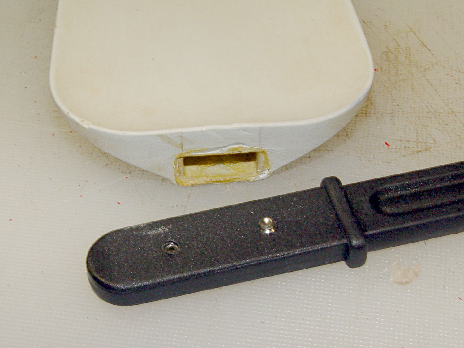
Shortly after we bought this kitchen scraper spatula (or whatever it’s called), the handle pulled out of the blade and left it sitting in a bowl of batter. That turned out to be unsurprising, given that neither side of the interface has any mechanical locking features. I rinsed the batter off, stuck some urethane glue inside, rammed the handle in place, and hoped for the best. Lacking any mechanical interlock and not bonding to either surface, the adhesive didn’t improve the situation.
So I recently added a pair of stainless 4-40 setscrews standing just proud of the handle’s surface that should dig into the blade and hold it in place:
After rebuilding the front end of the Samsung vacuum’s floor brush, I’d hoped that was the end of it; other than replacing the brush strips every now and again, it’s been cooperative. Recently, however, one of the wheels popped off, which revealed the minimal mechanism holding them in place:
Samsung Quiet Jet – floor brush wheel interior
Those four delicate latches have worn themselves and the hub to the point where they ride over the edge at the slightest provocation. I pulled both wheels off and packed three turns of insulated wire (one turn is visible in the photo, as it was an iterative process) around the outside of the clips, with the intent of restoring enough force to hold the wheels in place until we exhaust the lifetime supply of bags I bought for the thing…
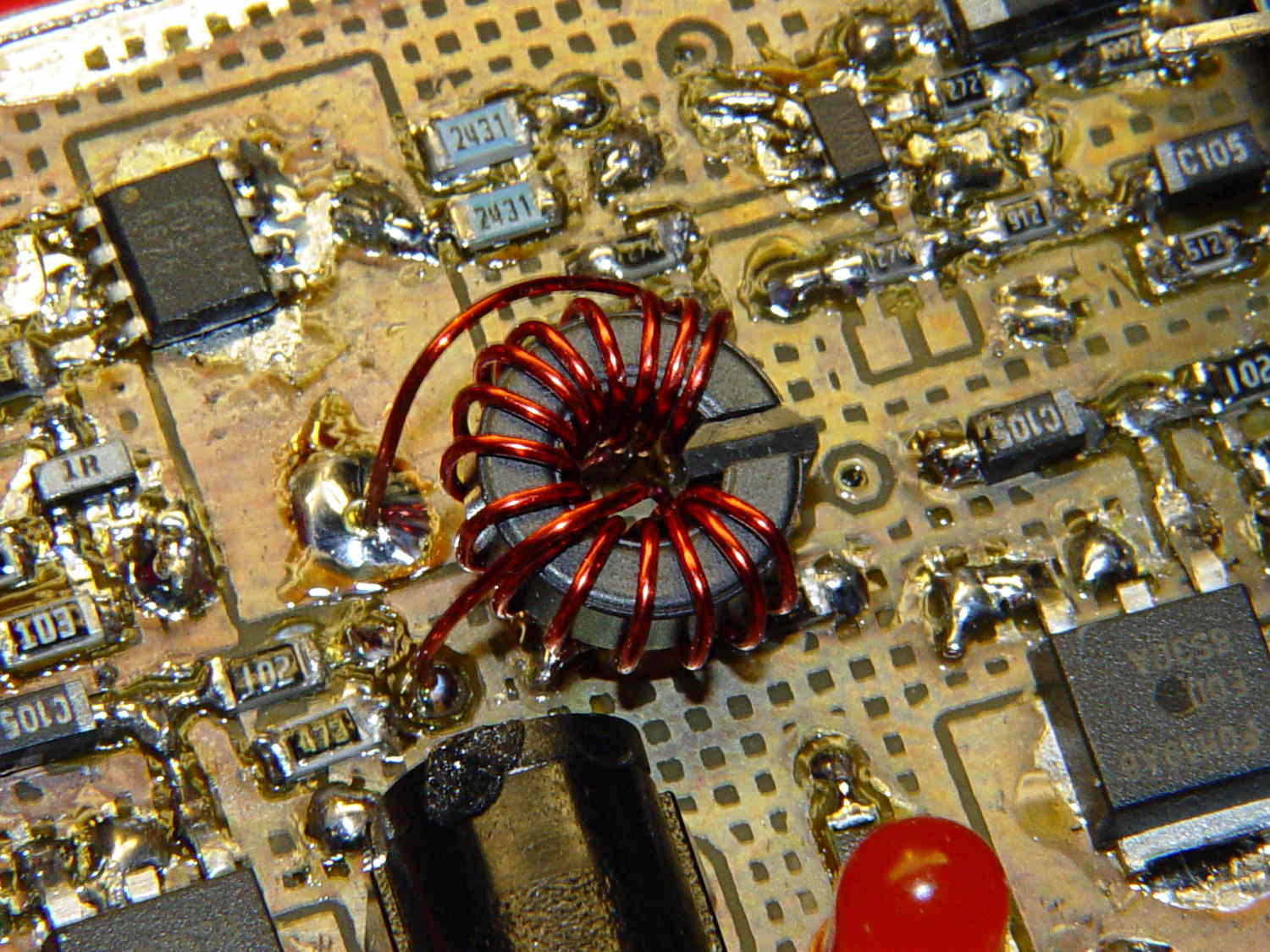
What’s the difference between the winding on this toroid:
Hall effect sensor – toroid CW field
And the winding on this one:
Hall effect sensor – toroid CCW field
Very good!
In the first picture, the top lead goes down the hole. In the second picture, the bottom lead goes down the hole.
Bonus question 1: Why is this important?
The winding’s chirality determines the direction of the magnetic field in the toroid by the right hand rule: grab the wire with your right hand, with your thumb pointed in the direction of (conventional) current flow, then your fingers wrap around the wire in the direction of the induced field.
The Hall effect sensor snuggled in the toroid’s gap produces a bipolar output that depends on both the magnetic field’s direction and intensity, so reversing the field direction changes the phase of the sensor output: an increasing field can either increase or decrease the sensor’s output.
Bonus question 2: For a given sensor orientation, what’s the probability of winding the toroid correctly on the first try?
It’s not practical to reverse the sensor orientation, the leads weren’t quite long enough to swap, and turning the toroid upside-down is effectively the same as swapping the too-short leads.
The size of the solder blob at the end of the top lead tells you everything you need to know about the sequence of the picvtures.
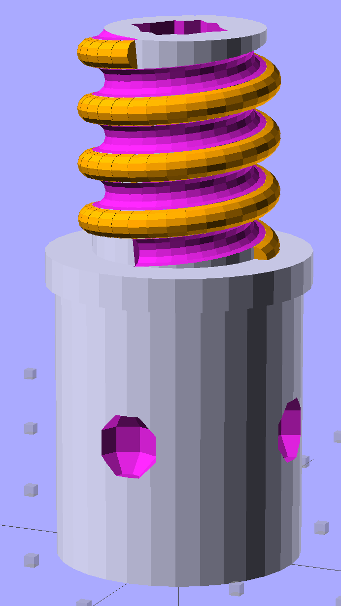
Although the current OpenSCAD could produce a solid model with the screw thread’s dedendum, I’d never actually printed one of them:
Broom Handle Screw – full thread – solid model
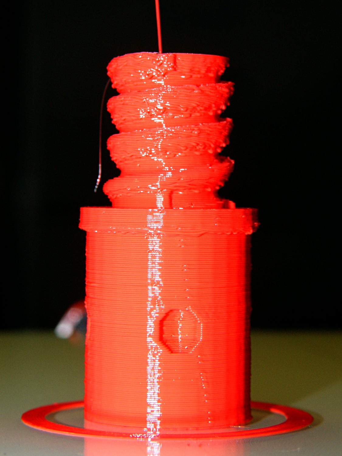
I need some fondlestuff illustrating how to handle overhangs, so I ran one standing vertically, which (pretty much as I expected) didn’t work well at all:
Broom Handle Screw – dedendum – vertical
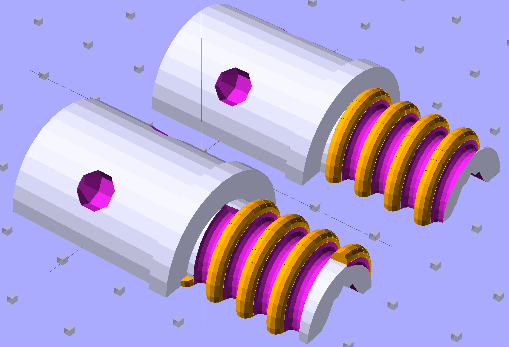
The trick is to split the model down the middle:
Broom Handle Screw – horizontal top
And put holes in each half for alignment pins:
Broom Handle Screw – horizontal bottom
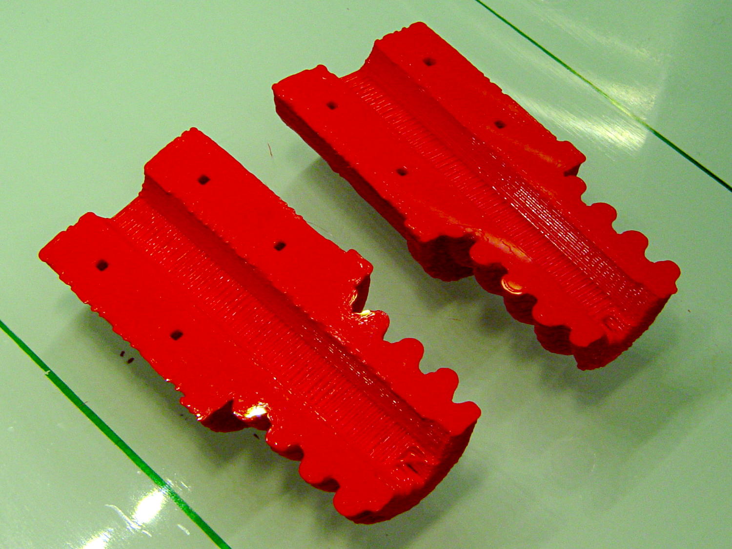
Then you can print it lying down:
Broom Handle Screw – horizontal – as-printed top
The internal overhang would probably call for some support material, particularly in the square recess at the end, but in this case it’s a lesson:
Glue some filament snippets into the holes, snap it together, and it looks just fine over there on the right:
Broom Handle Screw – orientation comparison
Doesn’t matter how many I print, it still doesn’t make any economic sense as a broom repair…
The OpenSCAD source code now has a Layout variable to control the orientation and, not as shown in the model, the alignment pins have glue gutters in the first layer:
// Broom Handle Screw End Plug
// Ed Nisley KE4ZNU October 2013

Layout = "Horizontal";		// Vertical Horizontal Pin

UseDedendum = true;			// true to create full thread form

//- Extrusion parameters must match reality!

ThreadThick = 0.25;
ThreadWidth = 0.40;

HoleWindage = 0.2;

Protrusion = 0.1;			// make holes end cleanly

//----------------------
// Dimensions

PostOD = 22.3;				// post inside metal handle
PostLength = 25.0;

FlangeOD = 24.0;			// stop flange
FlangeLength = 3.0;

PitchDia = 15.5;			// thread center diameter
ScrewLength = 20.0;

ThreadFormOD = 2.5;			// diameter of thread form
ThreadPitch = 5.0;
NumSegments = 32;			//  .. number of cylinder approximations per turn

BoltOD = 7.0;				// clears 1/4-20 bolt
BoltSquare = 6.5;			// across flats
BoltHeadThick = 3.0;

RecessDia = 6.0;			// recesss to secure post in handle

OALength = PostLength + FlangeLength + ScrewLength;

SplitOC = 1.25*FlangeOD;	// separation in Horizontal layout
PinOD = 1.75;				// alignment pin diameter = filament stub
PinLength = 7.0;			//  ... length

$fn=8*4;					// default cylinder sides

echo("Pitch dia: ",PitchDia);
echo("Root dia: ",PitchDia - ThreadFormOD);
echo("Crest dia: ",PitchDia + ThreadFormOD);

Pi = 3.14159265358979;

//----------------------
// Useful routines

// Wrap cylindrical thread segments around larger plug cylinder

module CylinderThread(Pitch,Length,PitchDia,ThreadOD,PerTurn) {

CylFudge = 1.02;				// force overlap

    RotIncr = 1/PerTurn;
    PitchRad = PitchDia/2;

    Turns = Length/Pitch;
    NumCyls = Turns*PerTurn;

    ZStep = Pitch / PerTurn;

    HelixAngle = atan(Pitch/(Pi*PitchDia));
    CylLength = CylFudge * (Pi*(PitchDia + ThreadOD) / PerTurn) / cos(HelixAngle);

	for (i = [0:NumCyls-1]) {
		assign(Angle = 360*i/PerTurn)
			translate([PitchRad*cos(Angle),PitchRad*sin(Angle),i*ZStep])
				rotate([90+HelixAngle,0,Angle])
					cylinder(r1=ThreadOD/2,
							r2=ThreadOD/(2*CylFudge),
							h=CylLength,
							center=true,$fn=12);
	}
}

// Build complete plug

module ScrewPlug() {
	difference() {
		union() {
			cylinder(r=PostOD/2,h=PostLength);
			cylinder(r=PitchDia/2,h=OALength);
			translate([0,0,PostLength])
				cylinder(r=FlangeOD/2,h=FlangeLength);
			color("Orange")
			translate([0,0,(PostLength + FlangeLength)])
				CylinderThread(ThreadPitch,(ScrewLength - ThreadFormOD/2),PitchDia,ThreadFormOD,NumSegments);
		}

		translate([0,0,-Protrusion])
			PolyCyl(BoltOD,(OALength + 2*Protrusion),6);

		translate([0,0,(OALength - BoltHeadThick)])
			PolyCyl(BoltSquare,(BoltHeadThick + Protrusion),4);

		if (UseDedendum)
			translate([0,0,(PostLength + FlangeLength + ThreadFormOD/2 - ThreadPitch/(2*NumSegments))])
				rotate(-90 - 360/(2*NumSegments))
				CylinderThread(ThreadPitch,ScrewLength,PitchDia,ThreadFormOD,NumSegments);

		for (i = [0:90:270]) {
			rotate(45 + i)					// 45 works better with Horizontal layout
				translate([PostOD/2,0,PostLength/2])
					sphere(r=RecessDia/2,$fn=8);
		}
	}
}

// Locating pin hole with glue recess

module LocatingPin() {

	translate([0,0,-ThreadThick])
		PolyCyl((PinOD + 2*ThreadWidth),2*ThreadThick,4);
	translate([0,0,-(PinLength/2 + ThreadThick)])
		PolyCyl(PinOD,(PinLength + 2*ThreadThick),4);

}

module PolyCyl(Dia,Height,ForceSides=0) {			// based on nophead's polyholes

  Sides = (ForceSides != 0) ? ForceSides : (ceil(Dia) + 2);

  FixDia = Dia / cos(180/Sides);

  cylinder(r=(FixDia + HoleWindage)/2,
           h=Height,
	   $fn=Sides);
}

module ShowPegGrid(Space = 10.0,Size = 1.0) {

  Range = floor(50 / Space);

	for (x=[-Range:Range])
	  for (y=[-Range:Range])
		translate([x*Space,y*Space,Size/2])
		  %cube(Size,center=true);

}

//-------------------
// Build it...

ShowPegGrid();

if (Layout == "Vertical")
	ScrewPlug();

if (Layout == "Pin")
	LocatingPin();

if (Layout == "Horizontal")
	for (i=[-1,1])
		difference() {
			translate([i*SplitOC/2,PostLength/2,0])
				rotate([90,180*(i + 1)/2,0])
					ScrewPlug();

			translate([0,0,-FlangeOD/2])
				cube([2*OALength,2*OALength,FlangeOD],center=true);

			for (j=[-1,1], pin=[-1,1])
				assign(PinX = i*SplitOC/2 + pin*(PostOD + BoltOD)/4,
					   PinY = j*PostLength/4) {
					translate([PinX,PinY,0])
						rotate(45)
							LocatingPin();
					echo("i j pin: ",i,j,pin);
					echo("X Y: ",PinX,PinY);
				}
		}
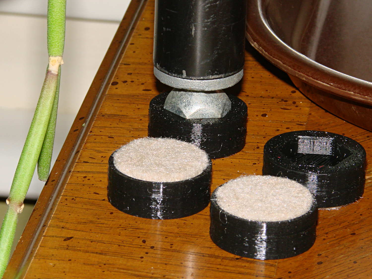
The houseplants have migrated indoors after spending a summer charging up in the sun on the patio, which means it’s time to replace the silicone rubber feet on the bottom of the plant shelves. This year, I printed a set of feet to fit the hex-head adjustable feet:
Plant Stand Foot – installed
The pencil-stem plant on the left, for whatever it’s worth, is a perfectly healthy Rhipsalis that greatly enjoyed the summer sun.
The feet print upside-down to give the surface around the hex a smooth finish. I used Slic3r’s Hilbert Curve for pattern a bit more interesting than the usual parallel lines:
Plant Shelf Foot – as built
The Hilbert curve doesn’t fit neatly into a non-rectangular shape, but it’s close enough.
The solid model includes the support structure:
Plant Shelf Foot – solid model – bottom
Which pops out cleanly:
Plant Shelf Foot – support material detail
Yes, that’s a shred of red filament embedded on the left side. Cleanliness is next to impossible…
The fuzzy felt feet come from a 6 mm thick slab of the stuff:
Plant Shelf Foot – cutting felt plugs
The round socket wall leaves about 2 mm of felt showing at the bottom; it’s not very compressible and that should suffice to keep the plastic off the table.
The OpenSCAD source code:
// Feet for a wire-shelf plant stand
// Ed Nisley KE4ZNU October 2013

Layout = "Build";			// Show Build

Support = true;

//- Extrusion parameters must match reality!
//  Print with 2 shells and 3 solid layers

ThreadThick = 0.25;
ThreadWidth = 0.40;

HoleWindage = 0.2;

Protrusion = 0.1;			// make holes end cleanly

//----------------------
// Dimensions

StandFootOD = 18.0;			// hex across flats
StandFootDepth = 5.0;		//  ... socket depth

FeltPadOD = 25.0;			// felt foot diameter
FeltPadDepth = 4.0;			//  ... depth

FootBaseThick = 6*ThreadThick;	// between foot and pad
FootWall = 4*ThreadWidth;		// around exterior

FootOD = 2*FootWall + max(StandFootOD,FeltPadOD);
echo(str("Foot OD: ",FootOD));

FootTall = StandFootDepth + FootBaseThick + FeltPadDepth;
echo(str(" ... height: "),FootTall);

NumSides = 8*4;

//----------------------
// Useful routines

module FootPad() {

	difference() {

		cylinder(r=FootOD/2,h=FootTall,$fn=NumSides);

		translate([0,0,FeltPadDepth + FootBaseThick])
			PolyCyl(StandFootOD,2*StandFootDepth,6);

		translate([0,0,-Protrusion])
			PolyCyl(FeltPadOD,(FeltPadDepth + Protrusion),NumSides);

	}
}

// Locating pin hole with glue recess

module LocatingPin() {

	translate([0,0,-ThreadThick])
		PolyCyl((PinOD + 2*ThreadWidth),2*ThreadThick,4);
	translate([0,0,-(PinLength/2 + ThreadThick)])
		PolyCyl(PinOD,(PinLength + 2*ThreadThick),4);

}

module PolyCyl(Dia,Height,ForceSides=0) {			// based on nophead's polyholes

  Sides = (ForceSides != 0) ? ForceSides : (ceil(Dia) + 2);

  FixDia = Dia / cos(180/Sides);

  cylinder(r=(FixDia + HoleWindage)/2,
           h=Height,
	   $fn=Sides);
}

module ShowPegGrid(Space = 10.0,Size = 1.0) {

  Range = floor(50 / Space);

	for (x=[-Range:Range])
	  for (y=[-Range:Range])
		translate([x*Space,y*Space,Size/2])
		  %cube(Size,center=true);

}

//-------------------
// Build it...

ShowPegGrid();

if (Layout == "Show")
	FootPad();

if (Layout == "Build") {
	translate([0,0,FootTall])
		rotate([180,0,0])
			FootPad();
	if (Support)
		color("Yellow")
			for (Seg=[0:5]) {
				rotate(30 + 360*Seg/6)
				translate([0,0,(StandFootDepth - ThreadThick)/2])
					cube([(StandFootOD - 3*ThreadWidth),
						  2*ThreadWidth,
						  (StandFootDepth - ThreadThick)],
						  center=true);
				}
}
Having just tightened the teeny screws that hold the joints in place for the first time since I glued it to the helmet, I’d say it’s working fine. The 2-56 elevation setscrew has worn a slight dent in the arc and the 3-48 azimuth screw worked slightly loose; the mirror didn’t fall apart, but the position wasn’t as stable as it should be.
If I ever re-do the design, I’ll try adding a recessed metal (brass?) strip along the top of that arc, as that’s the most finicky adjustment. Perhaps a shoe under the setscrew would be better?
Two years of road grit show up clearly against the yellow plastic, though:
Bike helmet mirror mount – two years
For the record, those 2-56 setscrews require 35 mil hex keys; as Eks reminds me, any design requiring those screws is just crazy talk.
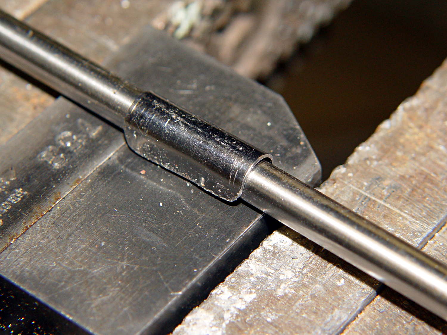
A few trips with the M2 convinced me that the cable to the relocated Z-min switch along the front of the X gantry needed a clip on each end and should not run under the gantry. This time I used the full width of the steel strap and bashed a neater curve around a length of drill rod:
M2 Z-min Cable Clip – forming
The new clips look a bit better with straight edges:
M2 Z-min Cable Clips – old vs new
The top view shows the new clips and cable location:
M2 Z-min Switch – top view
While I was at it, I trimmed the edges off the switch mounting block. Rather than figure out the trig required to hack off the corners, I applied linear_extrude() to a polygon() defined by some obvious points, then poked the same holes in the block:
Z-min Front Mount Switch Block – chamfer – solid model
It pretty much vanishes in the top view, but here’s a view from the +Y end of the platform:
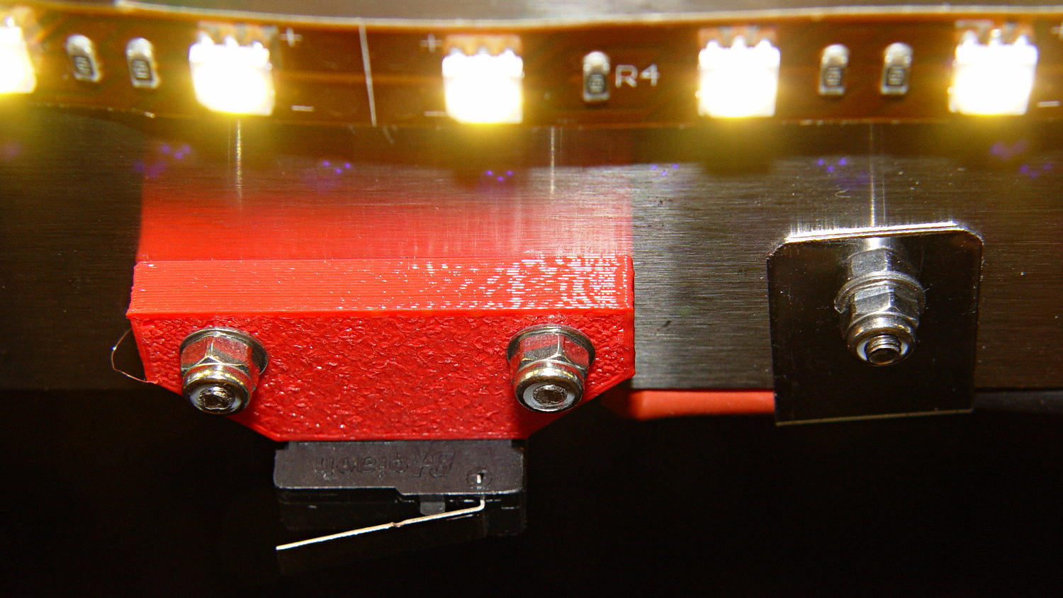
M2 Z-min Switch – bottom view
Despite all that maneuvering, the G92 Z-4.55 touchoff value remained the same!
If you’ve forgotten why all this makes sense, it’s a first pass at detecting the actual build platform position. The stock M2 uses that switch to detect the top of a screw attached to the Z-axis stage, which means it can’t sense the actual platform. The Z-min switch I added to the Thing-O-Matic convinced me that was the only way to fly; given the TOM’s plywood-and-acrylic frame, it was essentially mandatory.
Mounting the switch on the extruder would allow probing the entire platform, which would allow on-the-fly correction for both average height and (non-)flatness, but that’s a whole ‘nother project.
The OpenSCAD source code:
// Block to mount M2 Z-min switch on X gantry
// Ed Nisley KE4ZNU - Oct 2013

//- Extrusion parameters - must match reality!

ThreadThick = 0.25;
ThreadWidth = 0.40;

function IntegerMultiple(Size,Unit) = Unit * ceil(Size / Unit);

Protrusion = 0.1;

HoleWindage = 0.2;

//- Sizes

SwitchLength = 20.0;					// switch size across front of block

SwitchScrewOD = 2.05;					// microswitch screw tapping
SwitchScrewOC = 9.5;					//  ... on-center spacing

GantryScrewOD = 3.0;					// X rail screw clearance
GantryScrewOC = 25.0;					//  ... on-center spacing along X
GantryScrewOffset = 12.0;				//  ... Y offset from gantry front

BlockSize = [1.5*GantryScrewOC,17.0,5.0];			// XYZ dimensions as mounted
HalfBlock = BlockSize/2;

SwitchScrewLength = BlockSize[1] - 5*ThreadWidth;	// net length of switch screws
echo("Max switch screw length: ",SwitchScrewLength + 5.0);		// ... allow switch thickness

ChamferAngle = atan((BlockSize[0] - SwitchLength)/(BlockSize[1]/2));
echo("Chamfer Angle: ",ChamferAngle);

//- Adjust hole diameter to make the size come out right

module PolyCyl(Dia,Height,ForceSides=0) {			// based on nophead's polyholes

  Sides = (ForceSides != 0) ? ForceSides : (ceil(Dia) + 2);

  FixDia = Dia / cos(180/Sides);

  cylinder(r=(FixDia + HoleWindage)/2,h=Height,$fn=Sides);
}

//- Put peg grid on build surface

module ShowPegGrid(Space = 10.0,Size = 1.0) {

  RangeX = floor(100 / Space);
  RangeY = floor(125 / Space);

	for (x=[-RangeX:RangeX])
	  for (y=[-RangeY:RangeY])
		translate([x*Space,y*Space,Size/2])
		  %cube(Size,center=true);

}

//- Define basic block shape

module BaseBlock() {
	translate([0,-GantryScrewOffset,0])
		linear_extrude(height=BlockSize[2])
		polygon(points=[[-HalfBlock[0],BlockSize[1]],
						[HalfBlock[0],BlockSize[1]],
						[HalfBlock[0],HalfBlock[1]],
						[SwitchLength/2,0],
						[-SwitchLength/2,0],
						[-HalfBlock[0],HalfBlock[1]]
						]);
}

//- Build it

ShowPegGrid();

difference() {
	BaseBlock();
	for (i=[-1,1]) {
		translate([i*GantryScrewOC/2,0,-Protrusion])
			rotate(-90)
				PolyCyl(GantryScrewOD,(BlockSize[2] + 2*Protrusion));
		translate([i*SwitchScrewOC/2,-(GantryScrewOffset + Protrusion),BlockSize[2]/2])
			rotate([-90,0,0])
				rotate(90)
					PolyCyl(SwitchScrewOD,(SwitchScrewLength + Protrusion));
	}
}