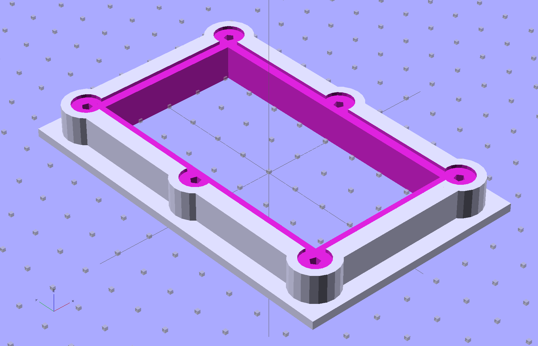
Fairly obviously, taping the Z-min switch to the back of the X gantry isn’t a long-term solution. There’s just enough clearance between the extruder and the X gantry for the switch, so I made a small block with clearance holes for the screws holding the X axis linear slide rail in place and tapping holes for the M2.5×0.45 screws in the switch:

Not much to it, is there? That printed just fine with the taped-in-place switch and exactly fit the screws; the rail screws dropped right through the holes and the switch screws tapped their way in.
The stock M2 cable reaches to the front of the X gantry, but only with the switch mounted to the left side:
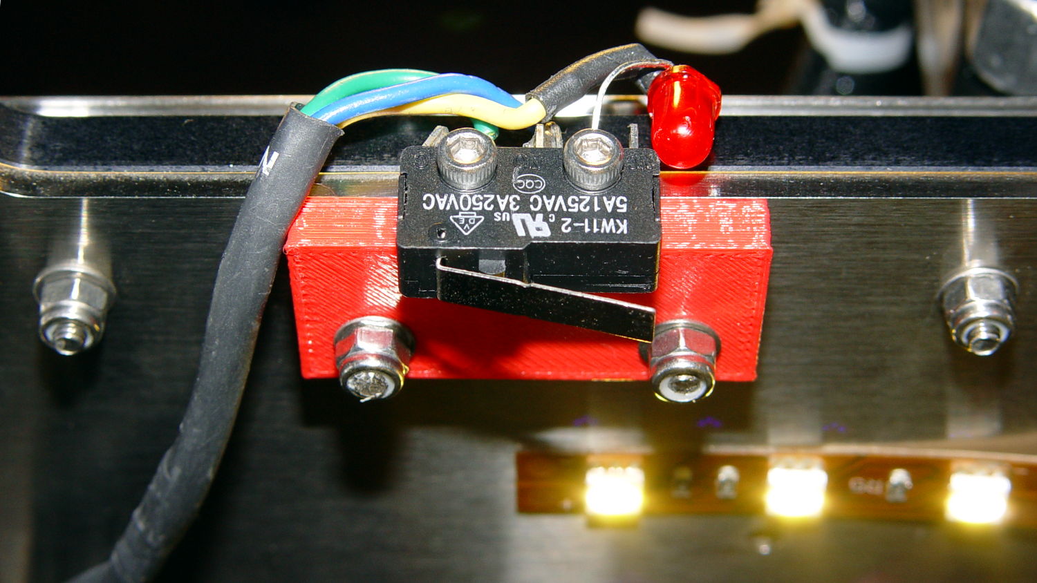
Those are 25 mm M3 screws shortened to about 19 mm; the one on the right looks a bit short to me, too.
Unfortunately, that spot on the gantry is the only place you can pick up the M2 with one hand: it balances perfectly when you (well, I) put four fingers between the five leftmost rail screws. It’s a beast to carry any other way, so that switch had to move.
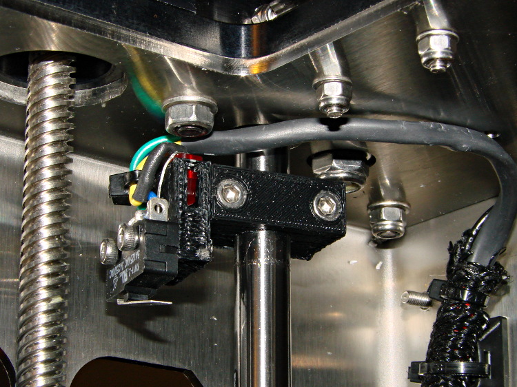
So I spliced in a snippet of six conductor cable, just so I could match the original color code, replaced the red through-hold LED with a blue SMD LED, and moved it to the middle of the gantry:

The view from below shows a sticky clamp holding a bight of the original cable and a small clamp (bent & drilled from a steel strap) holding the new cable in place:

It’s once again possible to grab the printer and lug it away…
The first test piece was Madscifi’s classic Tiny Toy Dump Truck, because I needed a show-n-tell tchotchke for a Squidwrench meeting:
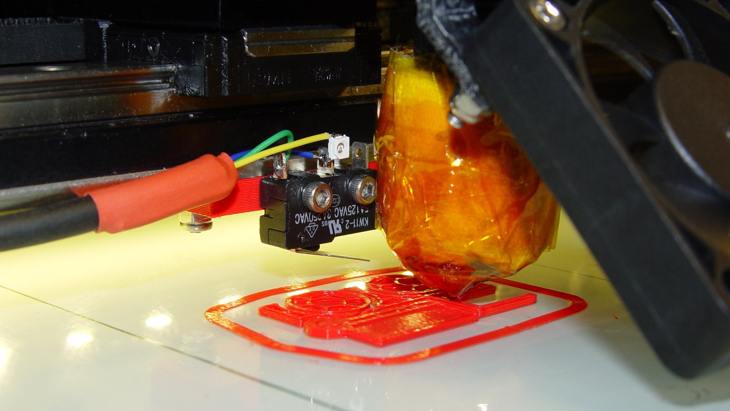
Yes, that dangling switch lever looks precarious, but it can’t touch the platform because the nozzle is below it.
With the switch in place, I melted a blob of solder atop the brass tubing on the platform, popped it off, and removed the residue with a razor scraper.
Before doing the truck, however, I had to recalibrate the Z switch and make the homing sequence do a different dance:
- Home Y and leave the platform at the rear
- Home X and move it to the far right to clear the platform
- Home Z against the platform glass
The complete start.gcode sequence (which isn’t really a separate file in Slic3r, but the notation helps keep things straight):
;-- Slic3r Start G-Code for M2 starts --
;  Ed Nisley KE4NZU - 7 Oct 2013
; Z-min switch at platform, must move nozzle to X=130 to clear platform
M140 S[first_layer_bed_temperature]	; start bed heating
G90				; absolute coordinates
G21				; millimeters
M83				; relative extrusion distance
M84				; disable stepper current
;G4 S3			; allow Z stage to freefall to the floor
G28 Y0			; home Y to be sure of clearing probe point in X
G92 Y-127 		; set origin to 0 = center of plate
G28 X0			; home X
G92 X-95		; set origin to 0 = center of plate
G1 X130 F30000	; move off platform to right side
G28 Z0			; home Z
G92 Z-4.55		; set origin to measured z offset
G0 Z10 F2000    ; get nozzle clearance
G0 X0 Y-124 Z3.0 F20000     ; set up for priming
M190 S[first_layer_bed_temperature]	; wait for bed to finish heating
M109 S[first_layer_temperature]	; set extruder temperature and wait
G1 Z0.0 F2000	; plug extruder on plate
G1 E10 F300		; prime to get pressure
G1 Z5 F2000		; rise above blob
G1 X5 Y-123 F30000	; move away from blob
G1 Z0.0 F2000		; dab nozzle to remove outer snot
G4 P1			; pause to clear
G1 Z0.5 F2000		; clear bed for travel
;-- Slic3r Start G-Code ends --
The G92 Z-4.55 instruction sets the Z position (without moving the stage) to the measured difference between the switch trip point and the nozzle tip.
Finding that value is a two-step process:
- Manually home Z against the platform (with the nozzle off to the right!)
- Issue
G92 Z0to define the switch trip point as Z=0.0 - Move the Z stage downward by a known distance so it clears the nozzle
- Move the nozzle over the platform
- Measure the distance between nozzle and platform (perhaps with a tapered gauge)
- Subtract that measurement from the distance you moved the nozzle
For example, I lowered the platform by 7.0 mm and measured 2.6 mm between the nozzle and the platform, so the G92 value = -7.0 + 2.6 = -4.4. Put that in the start.gcode G92 instruction: G92 Z-4.4.
That’ll get you in the ballpark, so print a thinwall open box and measure its top-to-bottom height at the corners. The second box came out about 4.85 mm tall, which means the nozzle was 0.15 mm too close to the platform: subtract 0.15 from the G92 setting: -4.4 – 0.15 = -4.55.
The next thinwall box came out exactly 5.0 mm tall.
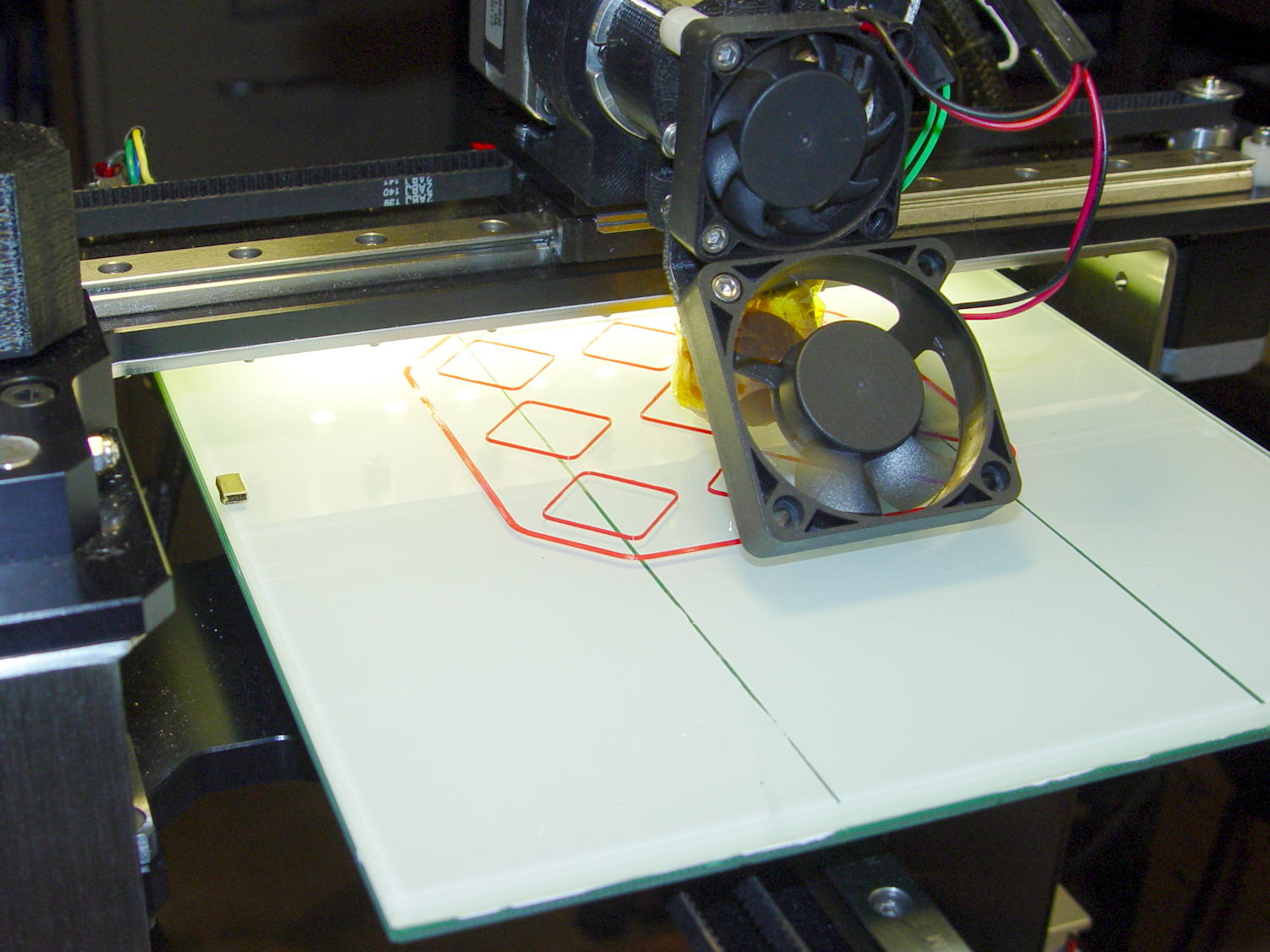
Then I could print that truck, which came out just fine, apart from the usual slight drooping where the filament must bridge the left side of the dump box:

After breaking one errant strand from the left side of the hinge, everything moved smoothly.
I must tinker up some G-Code to measure the switch closure point along the length of the platform, which would detect front-to-back tilt.
The OpenSCAD source code for the switch mounting block:
// Block to mount M2 Z-min switch on X gantry
// Ed Nisley KE4ZNU - Oct 2013

//- Extrusion parameters - must match reality!

ThreadThick = 0.25;
ThreadWidth = 0.40;

function IntegerMultiple(Size,Unit) = Unit * ceil(Size / Unit);

Protrusion = 0.1;

HoleWindage = 0.2;

//- Sizes

SwitchScrewOD = 2.05;					// microswitch screw tapping
SwitchScrewOC = 9.5;					//  ... on-center spacing

GantryScrewOD = 3.0;					// X rail screw clearance
GantryScrewOC = 25.0;					//  ... on-center spacing along X
GantryScrewOffset = 12.0;				//  ... Y offset from gantry front

BlockSize = [1.5*GantryScrewOC,17.0,5.0];			// XYZ dimensions as mounted

SwitchScrewLength = BlockSize[1] - 5*ThreadWidth;	// net length of switch screws
echo ("Max switch screw length: ",SwitchScrewLength + 5.0);		// ... allow switch thickness

//- Adjust hole diameter to make the size come out right

module PolyCyl(Dia,Height,ForceSides=0) {			// based on nophead's polyholes

  Sides = (ForceSides != 0) ? ForceSides : (ceil(Dia) + 2);

  FixDia = Dia / cos(180/Sides);

  cylinder(r=(FixDia + HoleWindage)/2,h=Height,$fn=Sides);
}

//- Put peg grid on build surface

module ShowPegGrid(Space = 10.0,Size = 1.0) {

  RangeX = floor(100 / Space);
  RangeY = floor(125 / Space);

	for (x=[-RangeX:RangeX])
	  for (y=[-RangeY:RangeY])
		translate([x*Space,y*Space,Size/2])
		  %cube(Size,center=true);

}

//- Build it

ShowPegGrid();

difference() {
	translate([-BlockSize[0]/2,-GantryScrewOffset,0])
		cube(BlockSize,center=false);
	for (i=[-1,1]) {
		translate([i*GantryScrewOC/2,0,-Protrusion])
			rotate(-90)
				PolyCyl(GantryScrewOD,(BlockSize[2] + 2*Protrusion));
		translate([i*SwitchScrewOC/2,-(GantryScrewOffset + Protrusion),BlockSize[2]/2])
			rotate([-90,0,0])
				rotate(90)
					PolyCyl(SwitchScrewOD,(SwitchScrewLength + Protrusion));
	}
}