The Smell of Molten Projects in the Morning

Ed Nisley's Blog: Shop notes, electronics, firmware, machinery, 3D printing, laser cuttery, and curiosities. Contents: 100% human thinking, 0% AI slop.

Category: Machine Shop

Mechanical widgetry

  • Makergear M2: Relocating the Z-Min Switch

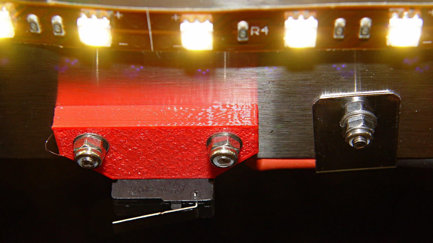
    Fairly obviously, taping the Z-min switch to the back of the X gantry isn’t a long-term solution. There’s just enough clearance between the extruder and the X gantry for the switch, so I made a small block with clearance holes for the screws holding the X axis linear slide rail in place and tapping holes for the M2.5×0.45 screws in the switch:

    Z-min Front Mount Switch Block - solid model
    Z-min Front Mount Switch Block – solid model

    Not much to it, is there? That printed just fine with the taped-in-place switch and exactly fit the screws; the rail screws dropped right through the holes and the switch screws tapped their way in.

    The stock M2 cable reaches to the front of the X gantry, but only with the switch mounted to the left side:

    M2 Z-min switch - left gantry
    M2 Z-min switch – left gantry

    Those are 25 mm M3 screws shortened to about 19 mm; the one on the right looks a bit short to me, too.

    Unfortunately, that spot on the gantry is the only place you can pick up the M2 with one hand: it balances perfectly when you (well, I) put four fingers between the five leftmost rail screws. It’s a beast to carry any other way, so that switch had to move.

    So I spliced in a snippet of six conductor cable, just so I could match the original color code, replaced the red through-hold LED with a blue SMD LED, and moved it to the middle of the gantry:

    M2 Z-min switch - center gantry
    M2 Z-min switch – center gantry

    The view from below shows a sticky clamp holding a bight of the original cable and a small clamp (bent & drilled from a steel strap) holding the new cable in place:

    M2 Z-min switch - center gantry - bottom view
    M2 Z-min switch – center gantry – bottom view

    It’s once again possible to grab the printer and lug it away…

    The first test piece was Madscifi’s classic Tiny Toy Dump Truck, because I needed a show-n-tell tchotchke for a Squidwrench meeting:

    M2 Z-min switch - center gantry - in action
    M2 Z-min switch – center gantry – in action

    Yes, that dangling switch lever looks precarious, but it can’t touch the platform because the nozzle is below it.

    With the switch in place, I melted a blob of solder atop the brass tubing on the platform, popped it off, and removed the residue with a razor scraper.

    Before doing the truck, however, I had to recalibrate the Z switch and make the homing sequence do a different dance:

    • Home Y and leave the platform at the rear
    • Home X and move it to the far right to clear the platform
    • Home Z against the platform glass

    The complete start.gcode sequence (which isn’t really a separate file in Slic3r, but the notation helps keep things straight):

    ;-- Slic3r Start G-Code for M2 starts --
    ;  Ed Nisley KE4NZU - 7 Oct 2013
    ; Z-min switch at platform, must move nozzle to X=130 to clear platform
    M140 S[first_layer_bed_temperature]	; start bed heating
    G90				; absolute coordinates
    G21				; millimeters
    M83				; relative extrusion distance
    M84				; disable stepper current
    ;G4 S3			; allow Z stage to freefall to the floor
    G28 Y0			; home Y to be sure of clearing probe point in X
    G92 Y-127 		; set origin to 0 = center of plate
    G28 X0			; home X
    G92 X-95		; set origin to 0 = center of plate
    G1 X130 F30000	; move off platform to right side
    G28 Z0			; home Z
    G92 Z-4.55		; set origin to measured z offset
    G0 Z10 F2000    ; get nozzle clearance
    G0 X0 Y-124 Z3.0 F20000     ; set up for priming
    M190 S[first_layer_bed_temperature]	; wait for bed to finish heating
    M109 S[first_layer_temperature]	; set extruder temperature and wait
    G1 Z0.0 F2000	; plug extruder on plate
    G1 E10 F300		; prime to get pressure
    G1 Z5 F2000		; rise above blob
    G1 X5 Y-123 F30000	; move away from blob
    G1 Z0.0 F2000		; dab nozzle to remove outer snot
    G4 P1			; pause to clear
    G1 Z0.5 F2000		; clear bed for travel
    ;-- Slic3r Start G-Code ends --
    

    The G92 Z-4.55 instruction sets the Z position (without moving the stage) to the measured difference between the switch trip point and the nozzle tip.

    Finding that value is a two-step process:

    • Manually home Z against the platform (with the nozzle off to the right!)
    • Issue G92 Z0 to define the switch trip point as Z=0.0
    • Move the Z stage downward by a known distance so it clears the nozzle
    • Move the nozzle over the platform
    • Measure the distance between nozzle and platform (perhaps with a tapered gauge)
    • Subtract that measurement from the distance you moved the nozzle

    For example, I lowered the platform by 7.0 mm and measured 2.6 mm between the nozzle and the platform, so the G92 value = -7.0 + 2.6 = -4.4. Put that in the start.gcode G92 instruction: G92 Z-4.4.

    That’ll get you in the ballpark, so print a thinwall open box and measure its top-to-bottom height at the corners. The second box came out about 4.85 mm tall, which means the nozzle was 0.15 mm too close to the platform: subtract 0.15 from the G92 setting: -4.4 – 0.15 = -4.55.

    The next thinwall box came out exactly 5.0 mm tall.

    Then I could print that truck, which came out just fine, apart from the usual slight drooping where the filament must bridge the left side of the dump box:

    M2 Tiny Toy Dump Truck test piece
    M2 Tiny Toy Dump Truck test piece

    After breaking one errant strand from the left side of the hinge, everything moved smoothly.

    I must tinker up some G-Code to measure the switch closure point along the length of the platform, which would detect front-to-back tilt.

    The OpenSCAD source code for the switch mounting block:

    // Block to mount M2 Z-min switch on X gantry
    // Ed Nisley KE4ZNU - Oct 2013
    
    //- Extrusion parameters - must match reality!
    
    ThreadThick = 0.25;
    ThreadWidth = 0.40;
    
    function IntegerMultiple(Size,Unit) = Unit * ceil(Size / Unit);
    
    Protrusion = 0.1;
    
    HoleWindage = 0.2;
    
    //- Sizes
    
    SwitchScrewOD = 2.05;					// microswitch screw tapping
    SwitchScrewOC = 9.5;					//  ... on-center spacing
    
    GantryScrewOD = 3.0;					// X rail screw clearance
    GantryScrewOC = 25.0;					//  ... on-center spacing along X
    GantryScrewOffset = 12.0;				//  ... Y offset from gantry front
    
    BlockSize = [1.5*GantryScrewOC,17.0,5.0];			// XYZ dimensions as mounted
    
    SwitchScrewLength = BlockSize[1] - 5*ThreadWidth;	// net length of switch screws
    echo ("Max switch screw length: ",SwitchScrewLength + 5.0);		// ... allow switch thickness
    
    //- Adjust hole diameter to make the size come out right
    
    module PolyCyl(Dia,Height,ForceSides=0) {			// based on nophead's polyholes
    
      Sides = (ForceSides != 0) ? ForceSides : (ceil(Dia) + 2);
    
      FixDia = Dia / cos(180/Sides);
    
      cylinder(r=(FixDia + HoleWindage)/2,h=Height,$fn=Sides);
    }
    
    //- Put peg grid on build surface
    
    module ShowPegGrid(Space = 10.0,Size = 1.0) {
    
      RangeX = floor(100 / Space);
      RangeY = floor(125 / Space);
    
    	for (x=[-RangeX:RangeX])
    	  for (y=[-RangeY:RangeY])
    		translate([x*Space,y*Space,Size/2])
    		  %cube(Size,center=true);
    
    }
    
    //- Build it
    
    ShowPegGrid();
    
    difference() {
    	translate([-BlockSize[0]/2,-GantryScrewOffset,0])
    		cube(BlockSize,center=false);
    	for (i=[-1,1]) {
    		translate([i*GantryScrewOC/2,0,-Protrusion])
    			rotate(-90)
    				PolyCyl(GantryScrewOD,(BlockSize[2] + 2*Protrusion));
    		translate([i*SwitchScrewOC/2,-(GantryScrewOffset + Protrusion),BlockSize[2]/2])
    			rotate([-90,0,0])
    				rotate(90)
    					PolyCyl(SwitchScrewOD,(SwitchScrewLength + Protrusion));
    	}
    }
    
  • Makergear M2 Improved Platform: Solid State Relay and Thermistor

    I’d originally planned to drive the new HBP with a boost converter from the 24 V supply brick, but that didn’t quite work out. The arrival of a 36 V brick from halfway around the planet solved that problem, but the RAMBo platform heater’s 15 A ATO fuse restricts it to 24 V and I don’t quite trust that MOSFET for high current applications, either.

    Sooo, I went full-frontal Cupcake with a solid state relay screwed to a pair of existing holes (!!!) in the M2’s frame:

    M2 - SSR for Improved HBP
    M2 – SSR for Improved HBP

    Note: that’s a DC-to-DC SSR, not the more common DC-to-AC SSR. Basically, it’s an up-armored optically isolated MOSFET, not a triac, and, yes, capitalizing acronyms and initalisms can be contentious.

    Because the RAMBo’s MOSFET now drives the piddly current required to activate the SSR, I rewired the power to apply the M2’s 19.5 V brick to all three inputs by adding two red jumpers on the right side of the Phoenix plugs:

    M2 HBP SSR Wiring
    M2 HBP SSR Wiring

    The M2’s hulking 12 V brick now resides in the Basement Warehouse’s Power Supply Annex.

    The HBP cable comes in from the right side and the 36 V supply arrives through the Powerpole connectors in the lower right. Tucking the ferrite slug on the 19.5 V supply behind the wire loom prevents the cable from pulling the Phoenix connectors out of the RAMBo board at an inopportune moment.

    The original M2 HBP wiring got uncomfortably warm carrying the 10+ A for that platform. It would probably work OK at a lower current, but I’d already put Powerpole connectors on the new HBP. So I ran that cable outside the loom and abandoned the original pair inside.

    The SSR switches the +36 V wire, leaving the HBP at 0 V when it’s not activated: supply hot → SSR → HBP → supply common. That makes no practical difference, but it feels like a Good Idea. Also, the Kapton tape across the SSR terminals should be barely adequate to prevent contact with random conductive clutter; I’m channeling the true spirit of DIY 3D printing…

    I don’t have a connector matching the M2’s 100 kΩ platform thermistor, either, so I just ran the new cable down the outside of the loom and conjured up a two-pin socket for the header on the RAMBo board:

    Improvised 2-pin header socket
    Improvised 2-pin header socket

    Plug it all together, tweak the startup G-Code to properly trip the Z-min switch at its new location, and it Just Works:

    M2 Improved HBP - alignment test
    M2 Improved HBP – alignment test

    Those are thinwall open boxes that came out 5±0.03 mm tall across the array, so the platform is just about as level / aligned as necessary for my simple needs.

    The Z-min switch will move to get rid of that stupid block epoxied to the platform, so I didn’t record the G-Code tweakage…

  • Makergear M2 Improved Platform: Mechanical Adjustments

    The PCB under the improved flat-top glass platform has three soldered-in-place M3 screws that fit the M2’s Y stage support:

    M2 - Improved HBP - bottom view
    M2 – Improved HBP – bottom view

    I applied a tiny rat-tail file to the holes until they became a free sliding fit for the screws.

    The wave springs are mostly decoration, as the silicone rubber disks now take the compression load from the screws, and the platform is quite rigidly mounted.

    The new platform eliminates the M2’s original aluminum support spider, the aluminum heater & heat spreader, and the corner supports & clips, all of which add up to about 780 g. I didn’t bother changing the Y axis acceleration to match, as all those numbers seem rubbery.

    Minus the support spider, the platform rides much lower on the Z axis stage than the M2’s platform. Unfortunately, the Z-min switch clamped to the top of the rear Z-axis guide rod can’t get any higher, even after rearranging the cable and fiddling with the LED:

    M2 - Z min limit switch
    M2 – Z min limit switch

    As a first-pass hack, I moved the switch to the rear of the X gantry and applied Gorilla Tape to hold it in place:

    M2 - Z-min switch at rear X gantry
    M2 – Z-min switch at rear X gantry

    That required a small block to raise the platform enough to activate the switch before hitting the nozzle. I epoxied a snippet of brass rectangle tube to the left edge of the platform, directly under the switch lever:

     M2 - Improved HBP - rear switch tab
    M2 – Improved HBP – rear switch tab

    The awkward position activates the switch with the platform as far to the rear as possible, so that you can’t inadvertently drag the dangling switch lever across the block in the wrong direction.

    I think it’s stupid, too, but it let me bring up the printer and make sure all the electronics kept working. The next step was to relocate the switch to a more rational place

  • Tour Easy: Handlebar Wrap

    img_3619 - Silicone tape on Tour Easy handlebarAfter more than a few years, the handlebar grips on my Tour Easy are rather worn, so I recently wrapped them with cheerful red and yellow silicone tape.

    Back in the day, you wrapped with cork tape and had to worry about the direction on each side. Silicone tape fuses into a solid mass and the orientation shouldn’t matter; that’s a Good Thing, because I’m not sure what direction would be correct in this situation.

    The yellow section covers the SRAM twist grip, which means it has a moving joint at each end. I suspect the tape will pull back from the larger part of the grip and form an unsightly lump just behind it.

    It’s certainly much grippier than I expected…

    (The small pushbutton switch is the PTT for the amateur radio HT that does voice and APRS/GPS.)

  • Humanoid Finger

    Just for fun, I printed out Anthromod’s Kickstarter Hand finger:

    Anthromod Finger - parts on M2 platform
    Anthromod Finger – parts on M2 platform

    If I were doing it, I’d add 1.75 mm alignment holes in each part, but clamping each phalange in both directions came out close enough:

    Anthromod Finger - clamping
    Anthromod Finger – clamping

    The tolerances were a bit tight and it required some trimming before all the joints flexed freely. I used short segments of 3 mm orange filament for the knuckle hinges and heat-staked the ends, rather than having to trim a trio of 3 mm screws:

    Anthromod Finger - detail
    Anthromod Finger – detail

    After making three short rubber bands by tying and trimming loops from a longer band, the finger curled up just like yours:

    Anthromod Finger - curled
    Anthromod Finger – curled

    The overall quality isn’t as good as I’d like: there’s a bit of uplift on the edges and corners. If I print another one, I want to try less than 0.2 infill and less cooling.


  • Sonicare Essence: Re-taping the Case

    Much to my astonishment, the ordinary adhesive tape holding the Sonicare Essence power toothbrush together lasted for a bit over a year. As the tape splits along the gap in the case, the coil driving the brush head begins vibrating inside its nest, making a truly horrendous racket.

    The new fix looks a bit odd, but works fine:

    Sonicare Essence - red tape
    Sonicare Essence – red tape

    The tape comes from Mad Phil’s stash and is, I think, splicing tape for reel-to-reel 1/4 inch recording tape: it has zero stretch, infinite strength, and adhesive that’s obviously lasted forever. The inside of the spool says “NOPI Made in Germany”, which doesn’t lead anywhere useful, although the NOPI name does seem to appear in a tape context.

    After a year, the replacement NiMH cells are doing fine, still operating about once a day for three weeks from a 24 hour charge.

  • 3D Printed PCB Stiffening Bracket

    The brassboard PCB for the Hall effect blinky light is too bendy for the SMD parts to survive much debugging, particularly with all the wires hanging off the edges, so I whipped up a stiff mounting bracket that captures the whole thing, with a flange that fits in the work stand arms:

    PCB Test Frame - solid model
    PCB Test Frame – solid model

    I ran some self-tapping 4-40 hex-head screws into the holes while the plastic was still warm on the M2’s platform:

    PCB stiffener with screws on M2 platform
    PCB stiffener with screws on M2 platform

    Six screws seem excessive and I’ll probably wind up using just the middle two, but there’s no harm in having more holes and fittings than you really need.

    The flange fits neatly into the board holder on the Electronics Workbench, above all the construction clutter:

    PCB stiffener in board holder
    PCB stiffener in board holder

    The nice thing about having a 3D printer: when you need an object like this, a couple of hours later you have one!

    The OpenSCAD source code, slightly improved based the results you see above:

    // Test support frame for Hall Effect LED Blinky Light
    // Ed Nisley KE4ZNU - Sept 2013
    
    ClampFlange = true;
    
    //- Extrusion parameters - must match reality!
    
    ThreadThick = 0.25;
    ThreadWidth = 0.40;
    
    function IntegerMultiple(Size,Unit) = Unit * ceil(Size / Unit);
    
    Protrusion = 0.1;
    
    HoleWindage = 0.2;
    
    //- Screw sizes
    
    inch = 25.4;
    
    Tap4_40 = 0.089 * inch;
    Clear4_40 = 0.110 * inch;
    Head4_40 = 0.211 * inch;
    Head4_40Thick = 0.065 * inch;
    Nut4_40Dia = 0.228 * inch;
    Nut4_40Thick = 0.086 * inch;
    Washer4_40OD = 0.270 * inch;
    Washer4_40ID = 0.123 * inch;
    
    //- PCB sizes
    
    PCBSize = [46.5,84.0,1.0];
    PCBShelf = 2.0;
    
    Clearance = 4*[ThreadWidth,ThreadWidth,0];
    
    WallThick = IntegerMultiple(4.0,ThreadWidth);
    FrameHeight = 5.0;
    
    ScrewOffset = 0.0 + Clear4_40/2;
    
    OAHeight = FrameHeight + Clearance[2] + PCBSize[2];
    
    FlangeExtension = 3.0;
    FlangeThick = IntegerMultiple(1.5,ThreadThick);
    Flange = PCBSize
    			+ 2*[ScrewOffset,ScrewOffset,0]
    			+ 2*[Washer4_40OD,Washer4_40OD,0]
    			+ [2*FlangeExtension,2*FlangeExtension,(FlangeThick - PCBSize[2])]
    			;
    
    echo("Flange: ",Flange);
    NumSides = 4*5;
    
    //- Adjust hole diameter to make the size come out right
    
    module PolyCyl(Dia,Height,ForceSides=0) {			// based on nophead's polyholes
    
      Sides = (ForceSides != 0) ? ForceSides : (ceil(Dia) + 2);
    
      FixDia = Dia / cos(180/Sides);
    
      cylinder(r=(FixDia + HoleWindage)/2,h=Height,$fn=Sides);
    }
    
    //- Put peg grid on build surface
    
    module ShowPegGrid(Space = 10.0,Size = 1.0) {
    
      RangeX = floor(100 / Space);
      RangeY = floor(125 / Space);
    
    	for (x=[-RangeX:RangeX])
    	  for (y=[-RangeY:RangeY])
    		translate([x*Space,y*Space,Size/2])
    		  %cube(Size,center=true);
    
    }
    
    //- Build it
    
    ShowPegGrid();
    
    difference() {
    	union() {									// body block and screw bosses
    		translate([0,0,OAHeight/2])
    			color("LightBlue")
    			cube(PCBSize + Clearance + [2*WallThick,2*WallThick,FrameHeight],center=true);
    		for (x=[-1,1], y=[-1,0,1]) {
    			translate([x*(PCBSize[0]/2 + ScrewOffset),
    						y*(PCBSize[1]/2 + ScrewOffset),
    						0])
    				color("Orchid") cylinder(r=Washer4_40OD,h=OAHeight,$fn=NumSides);
    		}
    		if (ClampFlange)
    			translate([0,0,Flange[2]/2])
    			color("SeaGreen") cube(Flange,center=true);
    	}
    
    	for (x=[-1,1], y=[-1,0,1]) {				// screw holes and washer recesses
    		translate([x*(PCBSize[0]/2 + ScrewOffset),
    					y*(PCBSize[1]/2 + ScrewOffset),
    					-Protrusion])
    			rotate((x-1)*90)
    			PolyCyl(Tap4_40,(OAHeight + 2*Protrusion));
    		translate([x*(PCBSize[0]/2 + ScrewOffset),
    					y*(PCBSize[1]/2 + ScrewOffset),
    					OAHeight - PCBSize[2]])
    			PolyCyl(1.2*Washer4_40OD,(PCBSize[2] + Protrusion),NumSides);
    	}
    
    	translate([0,0,OAHeight/2])					// through hole below PCB
    		cube(PCBSize - 2*[PCBShelf,PCBShelf,0] + [0,0,2*OAHeight],center=true);
    
    	translate([0,0,(OAHeight - (PCBSize[2] + Clearance[2])/2 + Protrusion/2)])	// PCB pocket on top
    		cube(PCBSize + Clearance + [0,0,Protrusion],center=true);
    }