Based on the idea of reducing a magazine’s capacity by installing a not “readily” modifiable(*) block, brazing an M3 nut to a magazine floor plate goes about as easily as you can expect.
The process:
- Drill 3 mm hole in the center of the inner plate boss
- Wire-brush the plate to remove the black coating
- Mount a nut on a spring-loaded screw
- Apply paste flux under the nut
- Align snippets of silver solder under the nut
- Fire the propane torch!
The flux is Ultra-Flux, a nasty concoction intended for silver solder, which in this case is Brownell’s Silvaloy 355 in strip form. Despite the name, it’s 56% silver and has much higher strength than soft tin-lead solder. Although I haven’t done any destructive testing, a good joint will be stronger than the base metals.
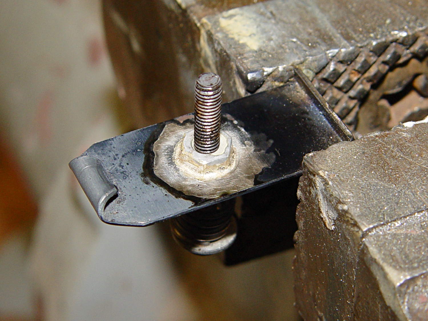
The setup before soldering the first nut:
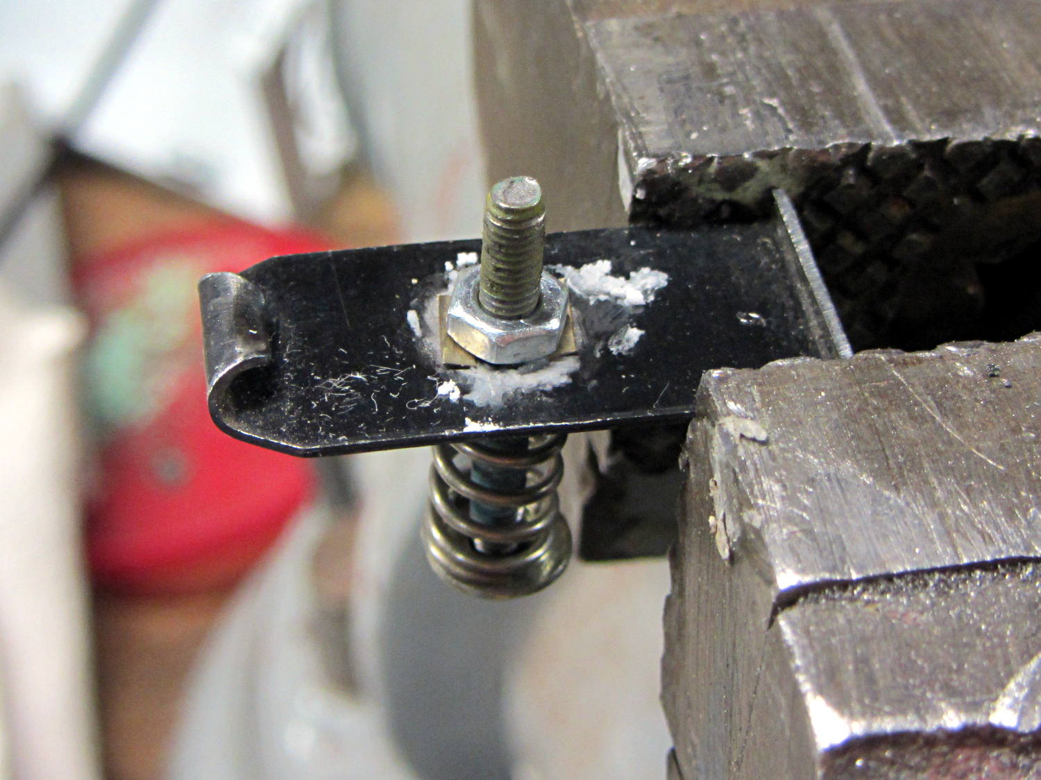
The spring holds the nut in the proper position, lets it settle straight down as the flux liquefies and the solder melts, then holds it flat against the floor plate to ensure a proper bond and a good fillet. I coated the screw with Tix Anti-Flux to ensure it didn’t become one with the nut.
The same joint after heating:

The garish red apparently comes from the Anti-Flux; the screw never got more than dull red and was cool by the time I shut off the torch and fiddled with the camera.
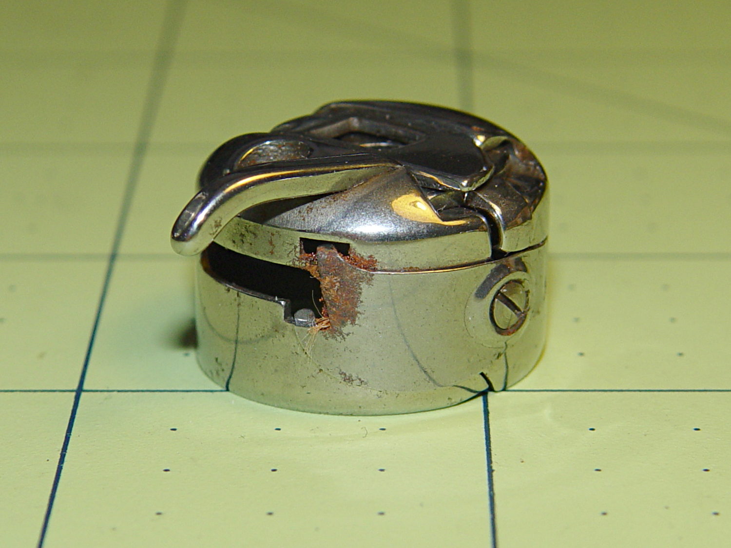
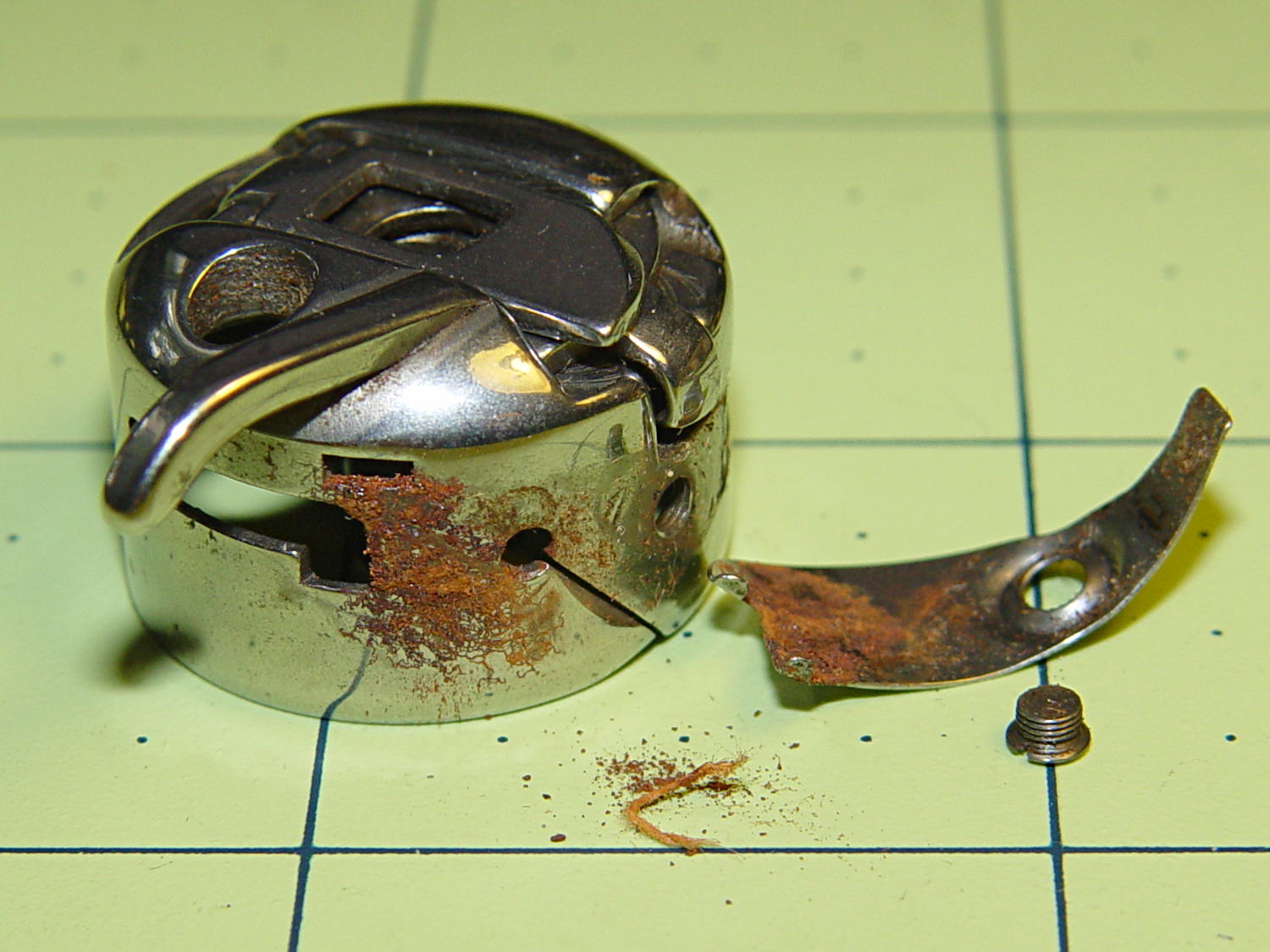
However, the rear of that first nut didn’t get a suitable fillet, so I reheated and removed it to reveal a section where the flux didn’t clean the steel and the solder didn’t flow:

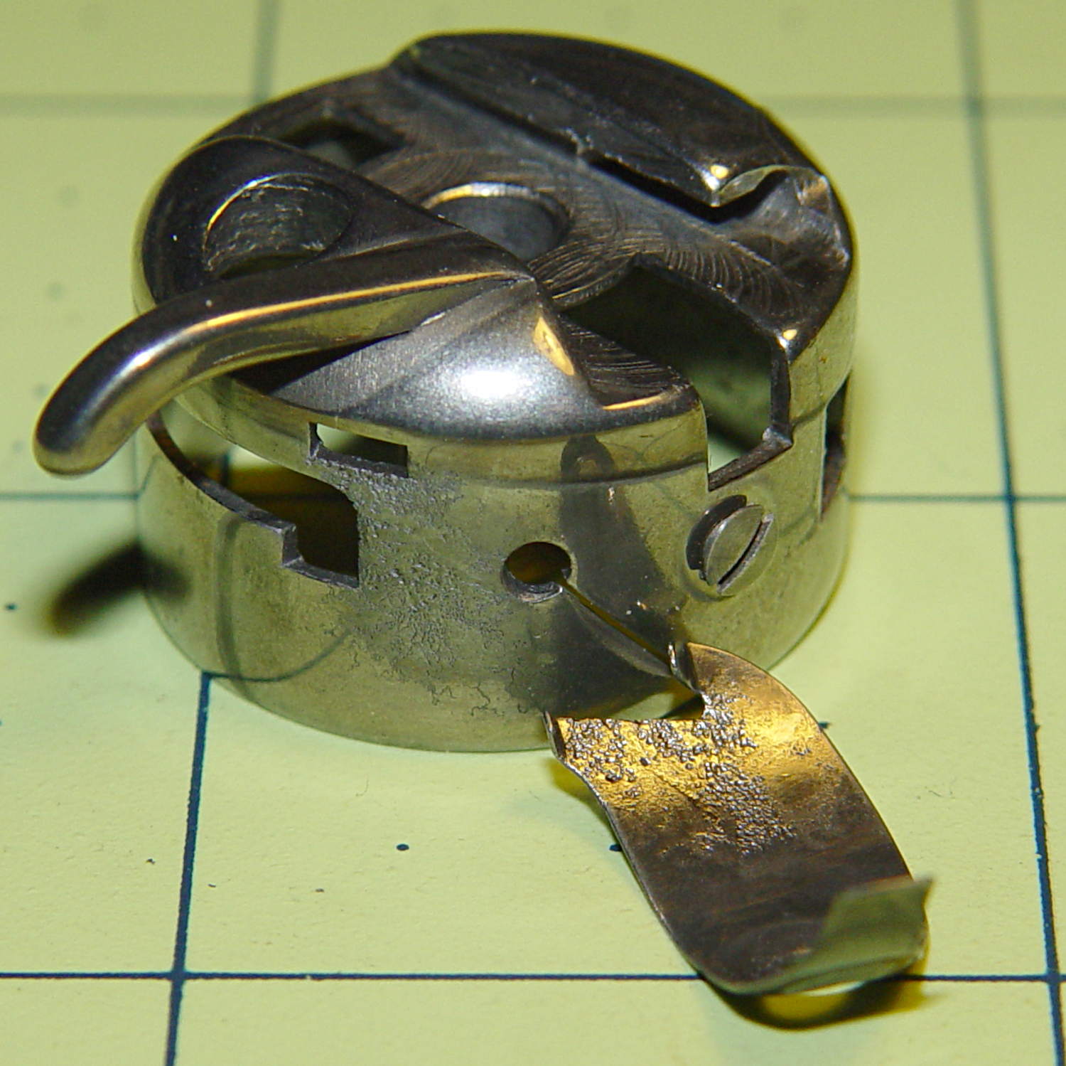
Note that the area below the middle of the nut can’t have a full solder joint, because the nut sits over the depression that forms the boss, thusly:
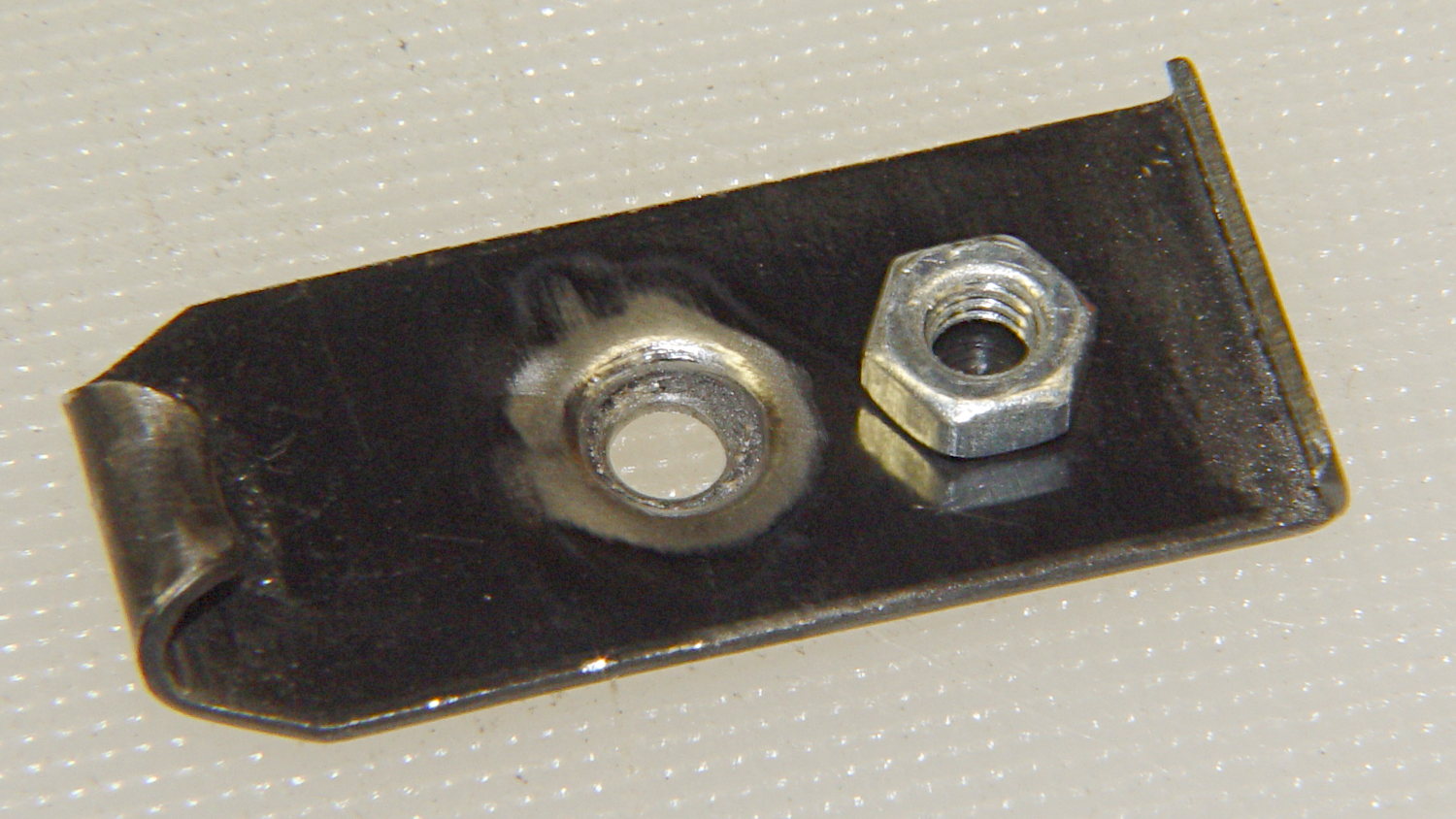
The solder fillet will, however, surround the nut and bond the ring near the flat part of the plate.
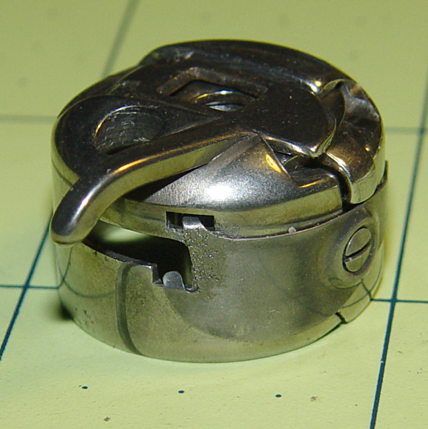
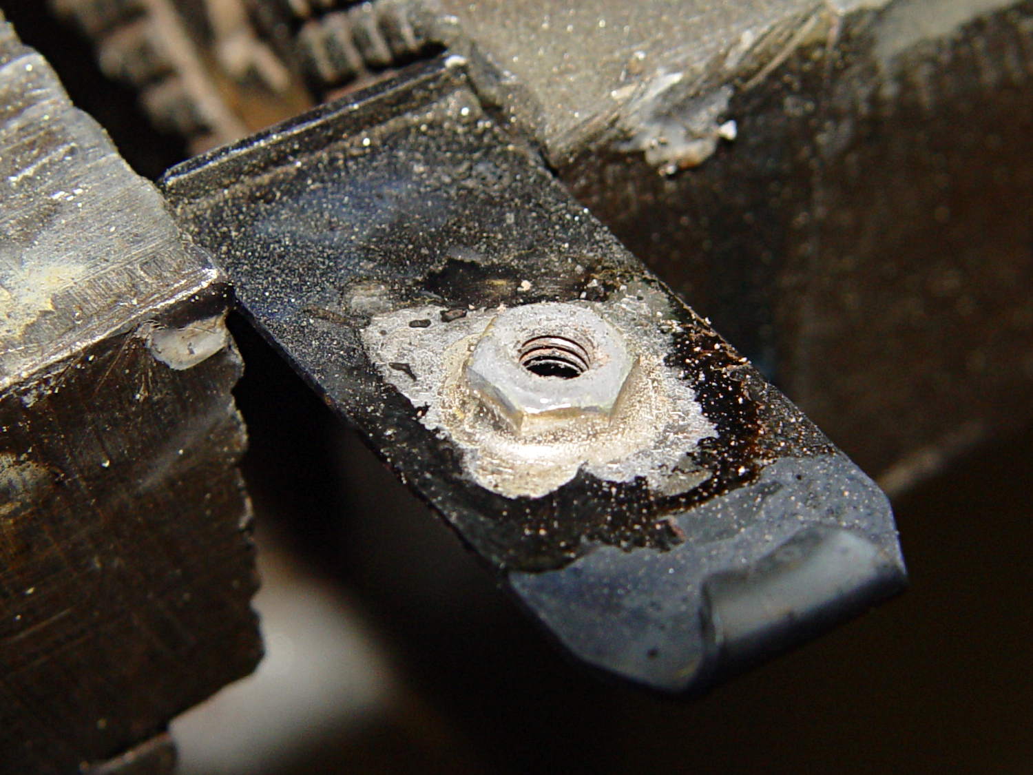
Properly cleaning and brushing that area produced a better joint under a new nut:

The fillet now extends all the way around the nut, as it should:
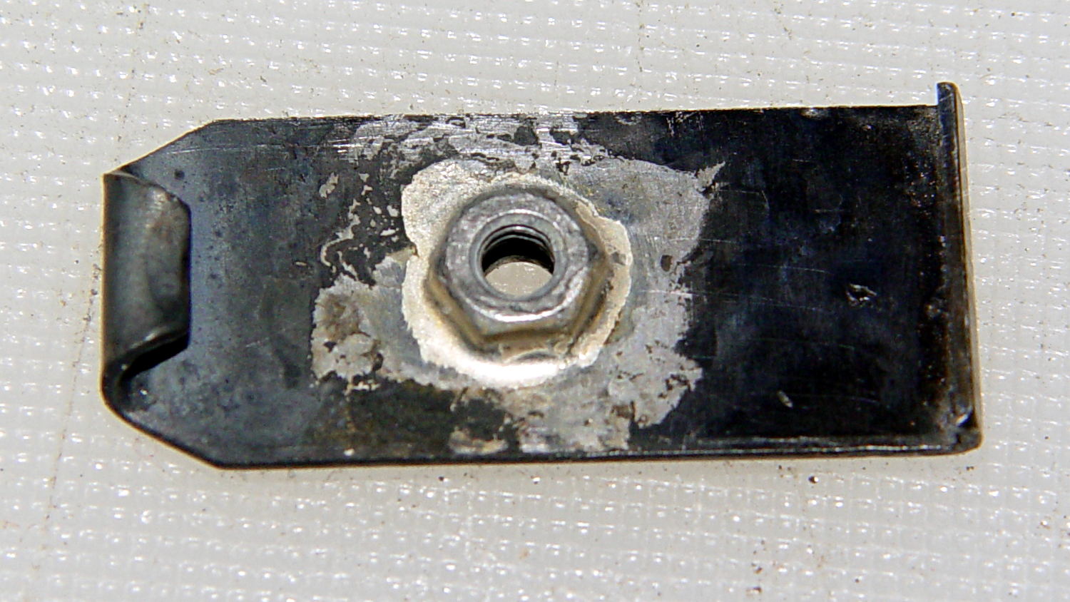
The crusty appearance comes from the flux residue, which comes off easily in a bath of boiling water to reveal a smooth fillet:
With cleanliness & good conduct in mind, the remainder of the floor plates brazed smoothly, with good results on the first heating:
Repeated heating took the starch right out of that poor spring, though…
With brazed plate in hand, the next step will be fitting suitable blocks to the individual floor plates.
(*) My state senator and assemblyperson (or, more exactly, their staffers) have been totally unhelpful in resolving the definition of “readily” as used in the legislation, to the extent that they don’t respond to emails asking about the result of meetings they said they attended with, e.g., State Police counsels, to get more information.