Ed Nisley's Blog: Shop notes, electronics, firmware, machinery, 3D printing, laser cuttery, and curiosities. Contents: 100% human thinking, 0% AI slop.
Our Larval Engineer asked for help with an OpenSCAD model of a 3D printable claw that, she says, has nothing at all to do with the upcoming Night of Little Horrors. Not having had an excuse to fiddle with the new (and lightly documented) sweep() functions, I gnawed on the sweep-drop.scad example until this popped out:
Swept Claw – solid model
That might be too aggressively sloped up near the top, but it’s a start.
The OpenSCAD source code:
use <sweep.scad>
use <scad-utils/transformations.scad>

function shape() = [[0,-25],[0,25],[100,0]];

function path(t) = [100*(1+sin(-90-t*90)), 0, (100 * t)];

step = 0.01;

path_transforms = [for (t=[0:step:1-step])
    translation(path(t)) *
    scaling([0.5*(1-t) + 0.1,0.75*(1-t) + 0.1,1])];

sweep(shape(), path_transforms);
It’s perfectly manifold and slices just as you’d expect; you could affix it to a mounting bracket easily enough.
Some notes on what’s going on…
The t index determines all the other values as a function of the layer from the base at t=0 to the top at t=0.99.
The shape() defines the overall triangular blade cross-section at the base; change the points / size to make it look like you want.
The path() defines the XYZ translation of each slab that’s extruded from the shape() cross-section. I think the Z value sets the offset & thickness of each slab. The constant 100 in the X value interacts with the overall size of the shape(). The 90 values inside the sin() function set the phase & scale t so the claw bends the right way; that took some fiddling.
The parameters in scaling() determine how the shape() shrinks along the path() as a function of the t parameter. The 0.1 Finagle Constants prevent the claw from tapering to a non-printable point at the tip. I think the Z value must be 1.000 to avoid weird non-manifold issues: the slabs must remain whatever thickness the sweep functions set them to be.
It compiles & renders almost instantly: much faster than I expected from the demos.
The folks who can (and do!) figure that kind of model (and the libraries behind it) from first principles have my undying admiration!
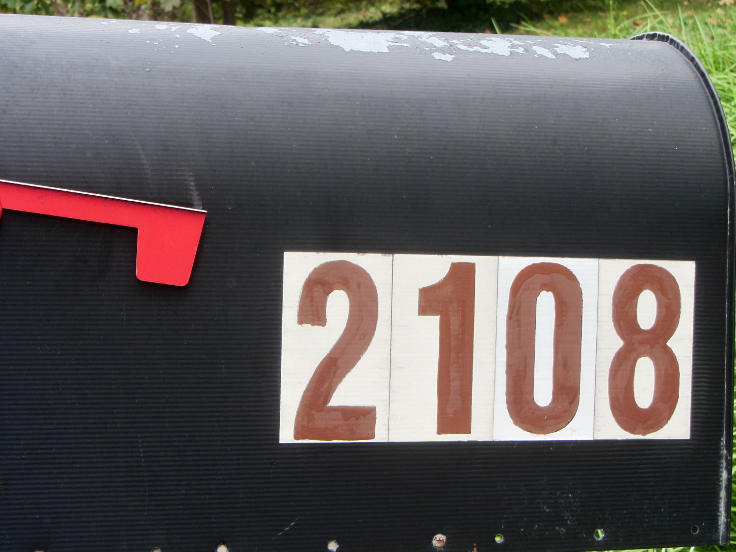
The south- and snowplow-facing numbers on the mailbox weren’t up to the challenge:
Mailbox – faded numbers
I wiped the crud off the reflective labels with denatured alcohol before painting, but that was the extent of the surface preparation.
I’m not getting graded on my ability to paint within the lines using a foam brush and that’s a Good Thing:
Mailbox – repainted numbers
That’s Rustoleum Rusty Metal Primer, chosen entirely because it was oil-based, outdoor-rated, and near the front of the shelf. I’m not going to topcoat it; that stuff is on its own. The slight color variations show still-wet primer here & there.
The north-facing numbers were in better shape, so a few dabs covered the obvious problems.
Hey, I wiped that peeling paint off the top of the box, too…
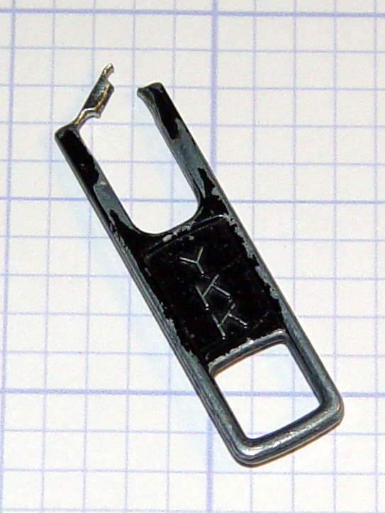
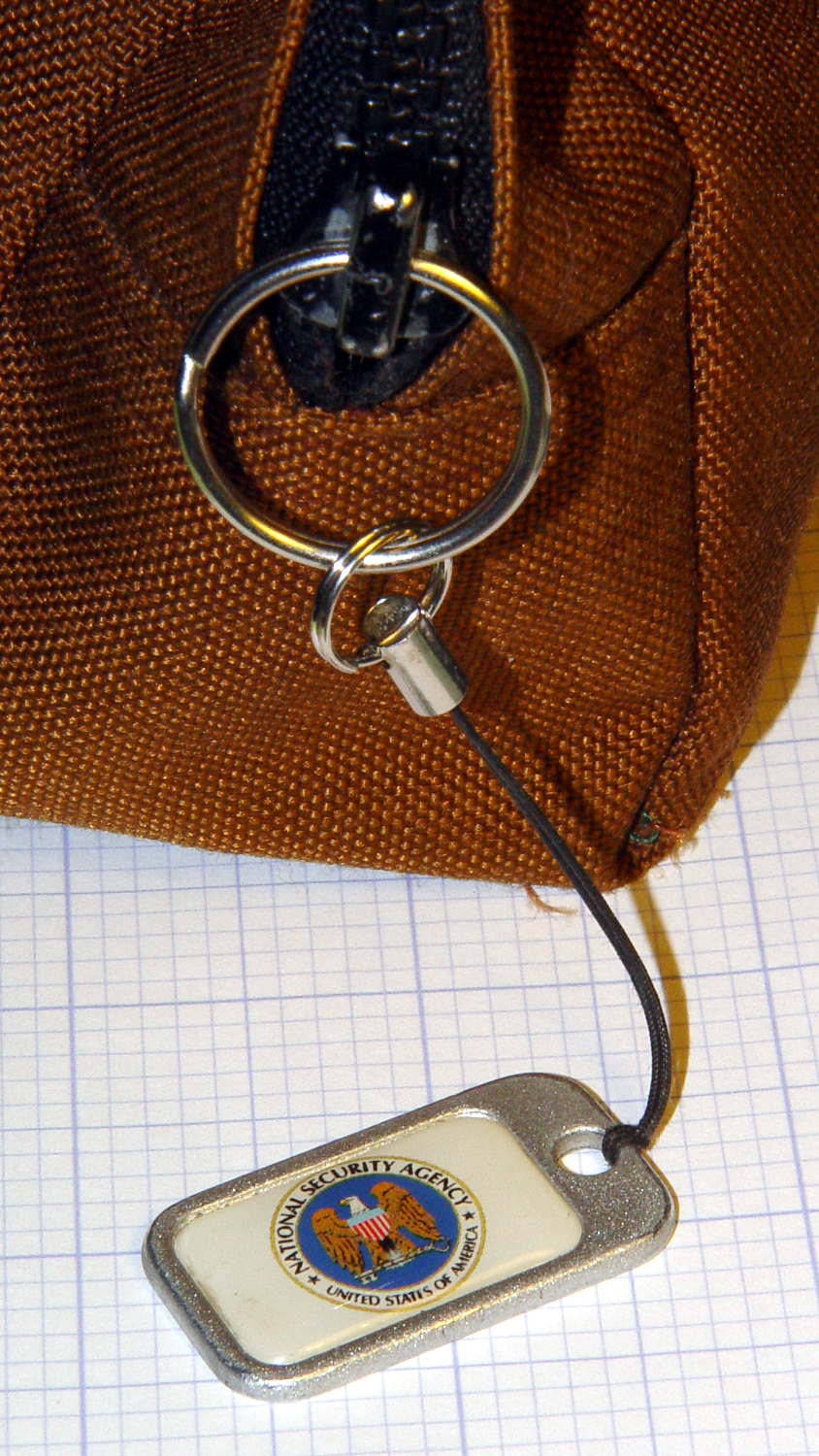
The NSA pull tabwent missing from my belt pack on the way back from a Squidwrench meeting and, despite diligent searching, remained missing for a several weeks. It reappeared from far under the Forester’s front seat, still attached to the severely eroded YKK zipper pull tab:
Eroded YKK Zipper Tab
A stout jump ring from the heap should avoid that problem for the foreseeable future:
Recently, the eye cups became difficult to pull out. The problem seemed to lie in the seal around the exterior of each tube, rather than with the internal mechanism, so I eased the tiniest possible drop of clock oil into each gap, spun the tubes, cycled them in-and-out, and wiped off essentially all of the oil as it spread over the exterior of the tubes.
The eye cups work fine again!
Frankly, I felt a like a Visigoth upgrading the Large Hadron Collider, but I trusted those old-school Leitz engineers would protect their optics from everything happening outside the sealed tubes.
For reasons not relevant here, I need a tripod mount for the Sony AS-30V that’s not quite so constraining as Sony’s Official skeleton mount + right-angle tripod bracket:
Sony HDR-AS30V – skeleton tripod mount
I must run a cable from the micro-HDMI port behind the hatch on the bottom of the camera to a display, but the Sony mount puts the hatch directly over the tripod platform and handle. Reversing the camera points it toward the handle, which then appears in the camera’s not-quite-fisheye view. Flipping the camera upside down sends the cable out the top, where it will put what I consider undue stress on the smallest high-density connector on any of my gadgets.
This Thingiverse model by maxspongebob is called a “Windshield Mount“, but has approximately the right features:
Sony HDR-AS30V holder – on tripod
The weird T-shaped dingus adapts micro- and mini-HDMI sockets to an ordinary HDMI cable (HDMI connector Types D, C, and A, respectively), serving as a placeholder for the yet-to-arrive 15 foot (probably 4.5 meter) cable.
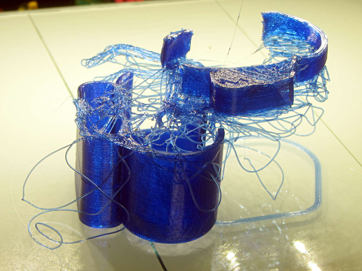
The mount isn’t designed for easy 3D printing, as it includes thin walls with chamfered edges, close tolerances, and aggressive bridging in dimension-critical areas. The first attempt failed when the minimal footprint (you’re looking at it in the picture above) pulled off the platform when the nozzle hit the lower bridge in the battery compartment:
Sony HDR-AS30V holder – failed print
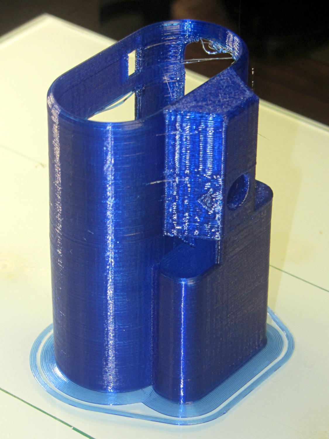
Surrounding the first layer with a 5 mm brim provided enough traction to finish the whole thing:
Sony HDR-AS30V holder – on platform
You can see some droopy threads across the openings; PETG bridges reasonably well, but the chamfers don’t provide good anchors. The opening for the camera hatch (on the far right rear) turned out slightly too short or, perhaps, the camera doesn’t seat quite far enough forward, which required some abrasive adjustment to accommodate the hatch.
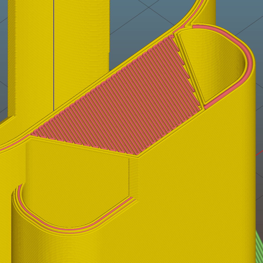
For unknown reasons, the top end of the battery compartment has a trapezoidal bridge:
Sony HDR-AS30V holder – trapezoidal bridge – Slic3r preview
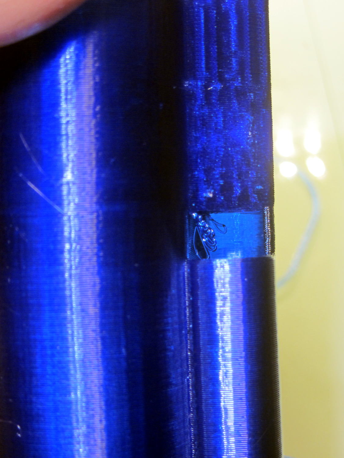
Which simply cannot be printed:
Sony HDR-AS30V holder – internal bridge failure
Cutting those threads out with an Xacto knife solved that problem.
The mount attaches to the tripod with a 1/4-20 nut trapped behind the hole next to the battery compartment. I grabbed an ordinary steel nut in a long normally closed tweezers, heated it over a butane lighter flame, threaded it onto a bolt stuck through the hole, and pulled it securely into the trap with exactly zero drama.
It has a very, very snug fit around the camera and battery that’s much better than a loose & floppy fit: there’s no positive retention latch.
This will serve as a prototype to see if the whole project works. If so, I’ll lash something together in OpenSCAD that should print a bit better, even if it looks like my usual brackets…