Replacing the hex nut traps with knurled insert cylinders slims the ends of the socket:

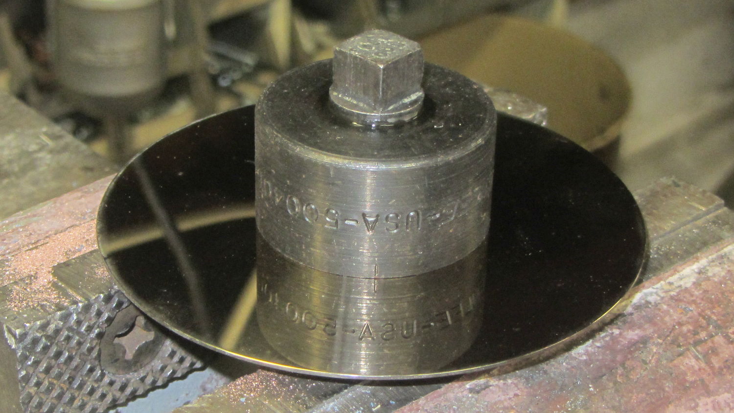
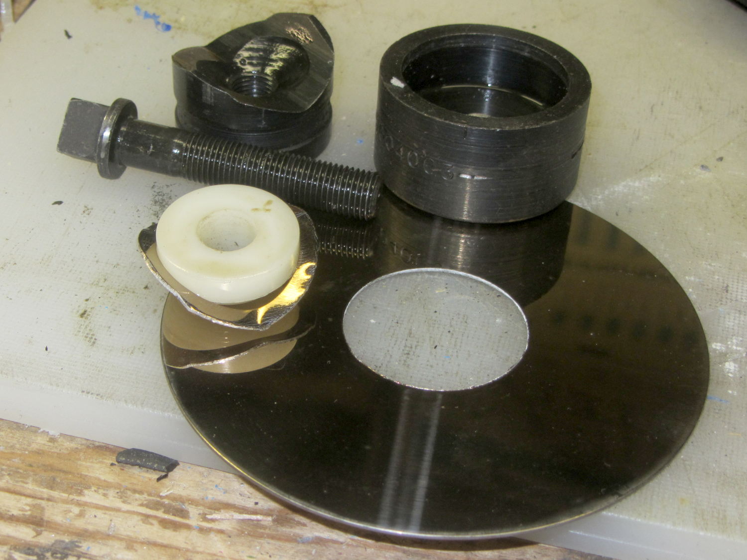
Making the raised part of the socket fit the 25 mm ID of a hard drive platter swells the midsection of the socket, but the platter won’t need any machining or punching:
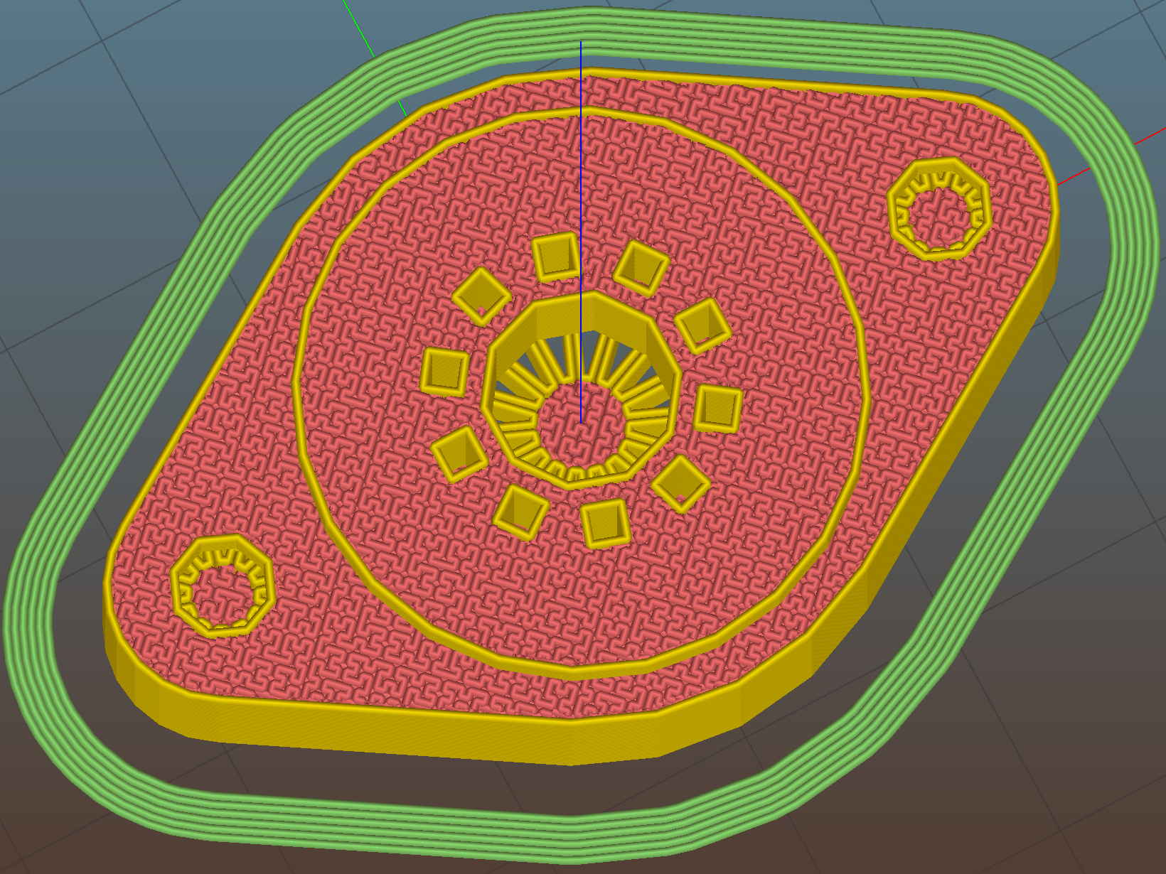
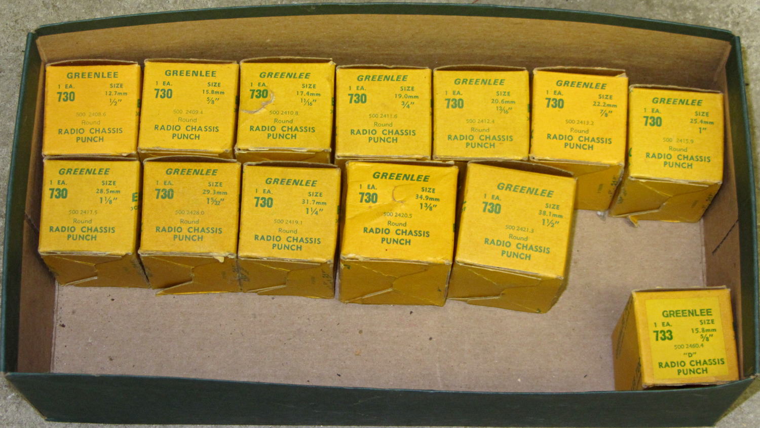
The octal and duodecar sockets will require a punch to open up the platter hole and all sockets require two drilled clearance holes for the screws. Given that I’ll eventually do this on the Sherline, maybe milling the hole for the bigger tubes will be faster & easier than manually punching them.
I moved the screw centers to 35 mm (from the historically accurate 28 mm) to accommodate the larger center, not that anybody will ever notice, and enlarged the central hole to 7.5 mm (from 5.0 mm) to let more light into the tube base.
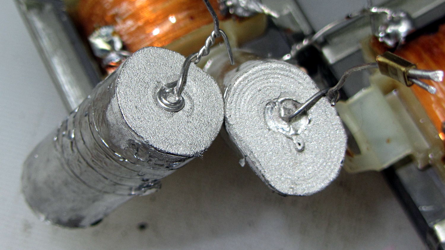
The support structures inside the (now much smaller) knurled insert cylinders might not be strictly necessary, but I left them in place to see how well they built. Which was perfectly, as it turns out, and they popped out with a slight push:

They’re just the cutest little things (those are 0.100 inch grid squares in the background):

Anyhow, the knurled inserts pressed into their holes with a slight shove:

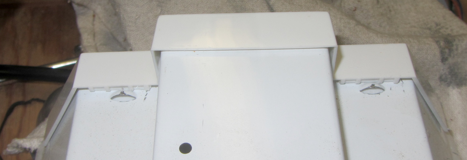
The chuck jaws were loose on the screw cutoff stud and stopped at the surface, putting the knurled inserts perfectly flush with the socket:

The surface looks very slightly distorted around the inserts, although it’s still smooth to the touch, and I think the PETG will slowly relax around the knurls. Even without heat or epoxy, they’re now impossible to pull out with any force I’m willing to apply to the screws threaded into them. Given that the platter screws will (be trying to) pull the inserts through the socket, I think a dry install will suffice for my simple needs.
Match-mark, drill #27 6-32 clearance holes, and the screws drop right in:

Those stainless steel pan-head 6-32 screws seem a bit large in comparison with the socket. Perhaps I should use 4-40 screws, even though they’re not, ahem, historically accurate.
The tube pin holes get hand-reamed with a #53 drill = 1.5 mm. That’s a bit over the nominal 1.1 mm pin diameter, but seems to provide both easy insertion and firm retention. For permanent installation, an adhesive would be in order.
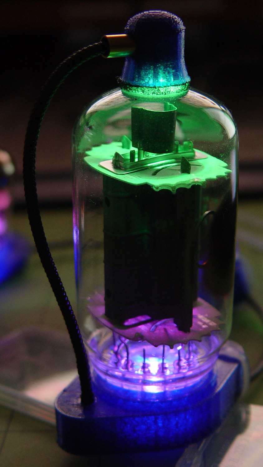
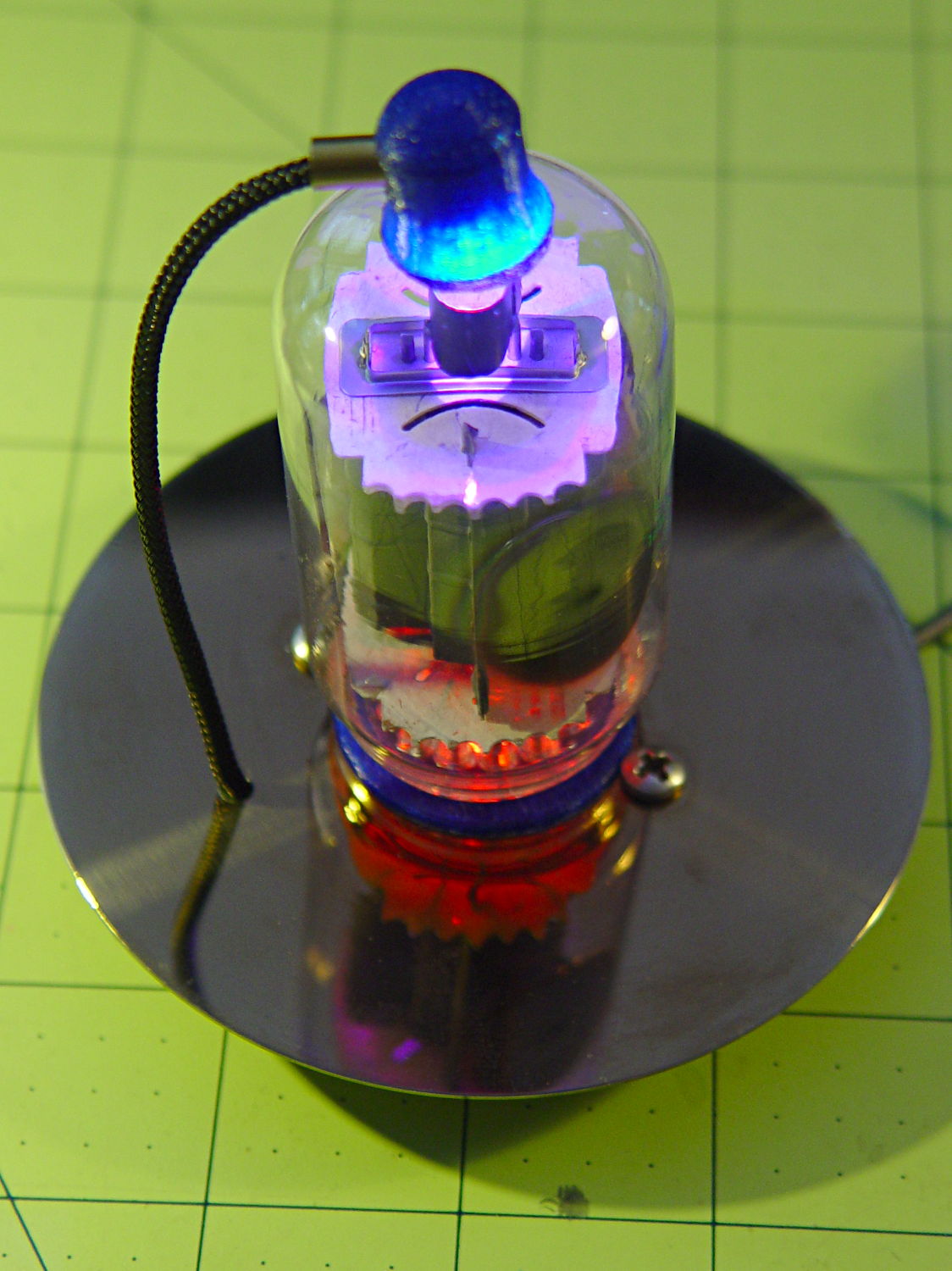
Buff off the fingerprints, stick the tube in place, and it looks pretty good:
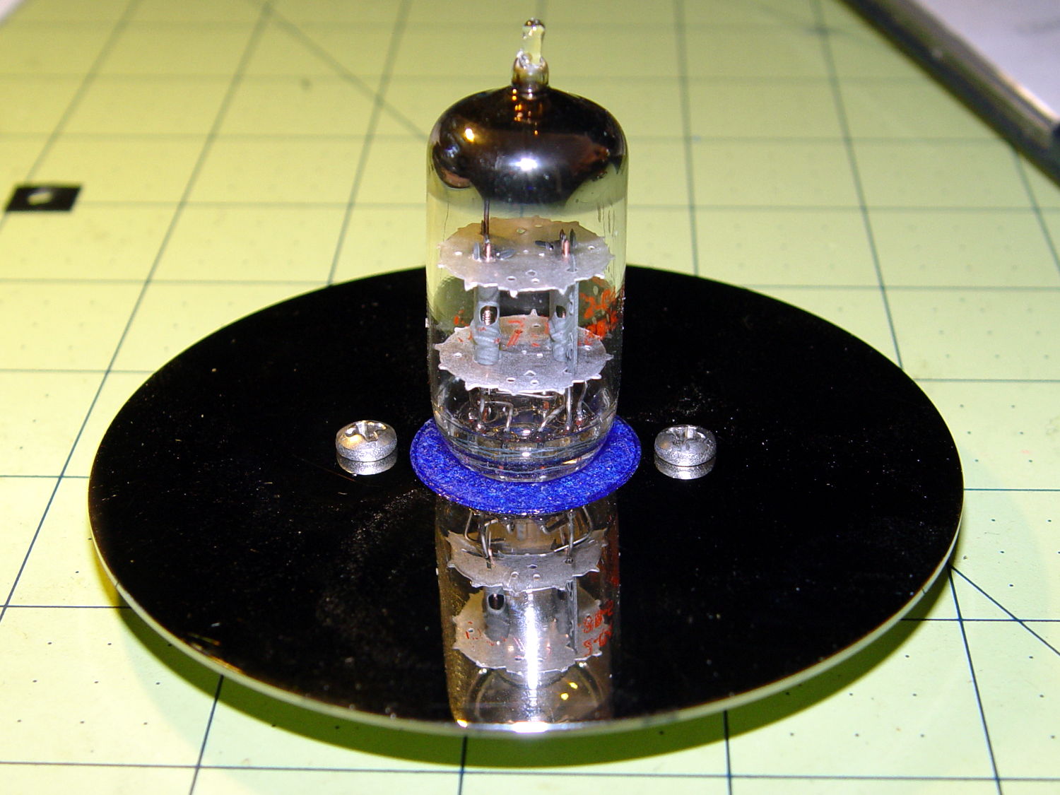
Yeah, those screws are too big. Maybe a brace of black M3 socket head screws would look better, despite a complete lack of historicity.
Now to wire it up and ponder how to build a base.
The OpenSCAD source code as a GitHub Gist:
| // Vacuum Tube LED Lights | |
| // Ed Nisley KE4ZNU February 2016 | |
| Layout = "Socket"; // Cap LampBase USBPort Socket(s) (Build)FinCap | |
| DefaultSocket = "Noval"; | |
| Section = false; // cross-section the object | |
| Support = true; | |
| //- Extrusion parameters must match reality! | |
| ThreadThick = 0.25; | |
| ThreadWidth = 0.40; | |
| HoleWindage = 0.2; | |
| Protrusion = 0.1; // make holes end cleanly | |
| inch = 25.4; | |
| function IntegerMultiple(Size,Unit) = Unit * ceil(Size / Unit); | |
| //———————- | |
| // Dimensions | |
| // https://en.wikipedia.org/wiki/Tube_socket#Summary_of_Base_Details | |
| // punch & screw OC modified for drive platter chassis plate | |
| // platter = 25 mm ID | |
| T_NAME = 0; // common name | |
| T_NUMPINS = 1; // total, with no allowance for keying | |
| T_PINBCD = 2; // tube pin circle diameter | |
| T_PINOD = 3; // … diameter | |
| T_PINLEN = 4; // … length (overestimate) | |
| T_HOLEOD = 5; // nominal panel hole from various sources | |
| T_PUNCHOD = 6; // panel hole optimized for inch-size Greenlee punches | |
| T_TUBEOD = 7; // envelope or base diameter | |
| T_PIPEOD = 8; // light pipe from LED to tube base | |
| T_SCREWOC = 9; // mounting screw holes | |
| // Name pins BCD dia length hole punch env pipe screw | |
| TubeData = [ | |
| ["Mini7", 8, 9.53, 1.016, 7.0, 16.0, 25.0, 18.0, 5.0, 35.0], // punch 11/16, screw 22.5 OC | |
| ["Octal", 8, 17.45, 2.36, 10.0, 36.2, (8 + 1)/8 * inch, 32.0, 11.5, 39.0], | |
| ["Noval", 10, 11.89, 1.1016, 7.0, 22.0, 25.0 , 21.0, 7.5, 35.0], // punch 7/8, screw 28.0 OC | |
| ["Duodecar", 13, 19.10, 1.05, 9.0, 32.0, (4 + 1)/4 * inch, 38.0, 12.5, 39.0], // aka Compactron | |
| ]; | |
| ID = 0; | |
| OD = 1; | |
| LENGTH = 2; | |
| Pixel = [7.0,10.0,3.0]; // ID = contact patch, OD = PCB dia, LENGTH = overall thickness | |
| Nut = [3.5,5.2,7.2]; // socket mounting nut recess — threaded insert | |
| NutSides = 8; | |
| BaseShim = 2*ThreadThick; // between pin holes and pixel top | |
| SocketFlange = 2.0; // rim around socket below punchout | |
| PanelThick = 1.5; // socket extension through punchout | |
| FinCutterOD = 1/8 * inch; | |
| FinCapSize = [(Pixel[OD] + 2*FinCutterOD),30.0,(10.0 + 2*Pixel[LENGTH])]; | |
| //———————- | |
| // Useful routines | |
| module PolyCyl(Dia,Height,ForceSides=0) { // based on nophead's polyholes | |
| Sides = (ForceSides != 0) ? ForceSides : (ceil(Dia) + 2); | |
| FixDia = Dia / cos(180/Sides); | |
| cylinder(r=(FixDia + HoleWindage)/2,h=Height,$fn=Sides); | |
| } | |
| //———————- | |
| // Tube cap | |
| CapTube = [4.0,3/16 * inch,10.0]; // brass tube for flying lead to cap LED | |
| CapSize = [Pixel[ID],(Pixel[OD] + 3.0),(CapTube[OD] + 2*Pixel[LENGTH])]; | |
| CapSides = 6*4; | |
| module Cap() { | |
| difference() { | |
| union() { | |
| cylinder(d=CapSize[OD],h=(CapSize[LENGTH]),$fn=CapSides); // main cap body | |
| translate([0,0,CapSize[LENGTH]]) // rounded top | |
| scale([1.0,1.0,0.65]) | |
| sphere(d=CapSize[OD]/cos(180/CapSides),$fn=CapSides); // cos() fixes slight undersize vs cylinder | |
| cylinder(d1=(CapSize[OD] + 2*3*ThreadWidth),d2=CapSize[OD],h=1.5*Pixel[LENGTH],$fn=CapSides); // skirt | |
| } | |
| translate([0,0,-Protrusion]) // bore for wiring to LED | |
| PolyCyl(CapSize[ID],(CapSize[LENGTH] + 3*ThreadThick + Protrusion),CapSides); | |
| translate([0,0,-Protrusion]) // PCB recess with clearance for tube dome | |
| PolyCyl(Pixel[OD],(1.5*Pixel[LENGTH] + Protrusion),CapSides); | |
| translate([0,0,(1.5*Pixel[LENGTH] – Protrusion)]) // small step + cone to retain PCB | |
| cylinder(d1=(Pixel[OD]/cos(180/CapSides)),d2=Pixel[ID],h=(Pixel[LENGTH] + Protrusion),$fn=CapSides); | |
| translate([0,0,(CapSize[LENGTH] – CapTube[OD]/(2*cos(180/8)))]) // hole for brass tube holding wire loom | |
| rotate([90,0,0]) rotate(180/8) | |
| PolyCyl(CapTube[OD],CapSize[OD],8); | |
| } | |
| } | |
| //———————- | |
| // Heatsink tube cap | |
| module FinCap() { | |
| CableOD = 3.5; // cable + braid diameter | |
| BulbOD = 3.75 * inch; // bulb OD; use 10 inches for flat | |
| echo(str("Fin Cutter: ",FinCutterOD)); | |
| FinSides = 2*4; | |
| BulbRadius = BulbOD / 2; | |
| BulbDepth = BulbRadius – sqrt(pow(BulbRadius,2) – pow(FinCapSize[OD],2)/4); | |
| echo(str("Bulb OD: ",BulbOD," recess: ",BulbDepth)); | |
| NumFins = floor(PI*FinCapSize[ID] / (2*FinCutterOD)); | |
| FinAngle = 360 / NumFins; | |
| echo(str("NumFins: ",NumFins," angle: ",FinAngle," deg")); | |
| difference() { | |
| union() { | |
| cylinder(d=FinCapSize[ID],h=FinCapSize[LENGTH],$fn=2*NumFins); // main body | |
| for (i = [0:NumFins – 1]) // fins | |
| rotate(i * FinAngle) | |
| hull() { | |
| translate([FinCapSize[ID]/2,0,0]) | |
| rotate(180/FinSides) | |
| cylinder(d=FinCutterOD,h=FinCapSize[LENGTH],$fn=FinSides); | |
| translate([(FinCapSize[OD] – FinCutterOD)/2,0,0]) | |
| rotate(180/FinSides) | |
| cylinder(d=FinCutterOD,h=FinCapSize[LENGTH],$fn=FinSides); | |
| } | |
| rotate(FinAngle/2) // cable entry boss | |
| translate([FinCapSize[ID]/2,0,FinCapSize[LENGTH]/2]) | |
| cube([FinCapSize[OD]/4,FinCapSize[OD]/4,FinCapSize[LENGTH]],center=true); | |
| } | |
| for (i = [1:NumFins – 1]) // fin inner gullets, omit cable entry side | |
| rotate(i * FinAngle + FinAngle/2) // joint isn't quite perfect, but OK | |
| translate([FinCapSize[ID]/2,0,-Protrusion]) | |
| rotate(0*180/FinSides) | |
| cylinder(d=FinCutterOD/cos(180/FinSides),h=(FinCapSize[LENGTH] + 2*Protrusion),$fn=FinSides); | |
| translate([0,0,-Protrusion]) // PCB recess | |
| PolyCyl(Pixel[OD],(1.5*Pixel[LENGTH] + Protrusion),FinSides); | |
| PolyCyl(Pixel[ID],(FinCapSize[LENGTH] – 3*ThreadThick),FinSides); // bore for LED wiring | |
| translate([0,0,(FinCapSize[LENGTH] – 3*ThreadThick – 2*CableOD/(2*cos(180/8)))]) // cable inlet | |
| rotate(FinAngle/2) rotate([0,90,0]) rotate(180/8) | |
| PolyCyl(CableOD,FinCapSize[OD],8); | |
| if (BulbOD <= 10.0 * inch) // curve for top of bulb | |
| translate([0,0,-(BulbRadius – BulbDepth + 2*ThreadThick)]) // … slightly flatten tips | |
| sphere(d=BulbOD,$fn=16*FinSides); | |
| } | |
| } | |
| //———————- | |
| // Aperture for USB-to-serial adapter snout | |
| // These are all magic numbers, of course | |
| module USBPort() { | |
| translate([0,28.0]) | |
| rotate([90,0,0]) | |
| linear_extrude(height=28.0) | |
| polygon(points=[ | |
| [0,0], | |
| [8.0,0], | |
| [8.0,4.0], | |
| // [4.0,4.0], | |
| [4.0,6.5], | |
| [-4.0,6.5], | |
| // [-4.0,4.0], | |
| [-8.0,4.0], | |
| [-8.0,0], | |
| ]); | |
| } | |
| //———————- | |
| // Box for Leviton ceramic lamp base | |
| module LampBase() { | |
| Bottom = 3.0; | |
| Base = [4.0*inch,4.5*inch,20.0 + Bottom]; | |
| Sides = 12*4; | |
| Retainer = [3.5,11.0,1.0]; // flat fiber washer holding lamp base screws in place | |
| StudSides = 8; | |
| StudOC = 3.5 * inch; | |
| Stud = [Nut[OD], // 6-32 tapped brass insert | |
| min(15.0,1.5*(Base[ID] – StudOC)/cos(180/StudSides)), // OD = big enough to merge with walls | |
| (Base[LENGTH] – Retainer[LENGTH])]; // leave room for retainer | |
| union() { | |
| difference() { | |
| rotate(180/Sides) | |
| cylinder(d=Base[OD],h=Base[LENGTH],$fn=Sides); | |
| rotate(180/Sides) | |
| translate([0,0,Bottom]) | |
| cylinder(d=Base[ID],h=Base[LENGTH],$fn=Sides); | |
| translate([0,-Base[OD]/2,Bottom + 1.2]) // mount on double-sided foam tape | |
| rotate(0) | |
| USBPort(); | |
| } | |
| for (i = [-1,1]) | |
| translate([i*StudOC/2,0,0]) | |
| rotate(180/StudSides) | |
| difference() { | |
| cylinder(d=Stud[OD],h=Stud[LENGTH],$fn=StudSides); | |
| translate([0,0,Bottom]) | |
| PolyCyl(Stud[ID],(Stud[LENGTH] – (Bottom – Protrusion)),6); | |
| } | |
| } | |
| } | |
| //———————- | |
| // Tube Socket | |
| module Socket(Name = DefaultSocket) { | |
| NumSides = 6*4; | |
| Tube = search([Name],TubeData,1,0)[0]; | |
| echo(str("Building ",TubeData[Tube][0]," socket")); | |
| echo(str(" Punch: ",TubeData[ID][T_PUNCHOD]," mm = ",TubeData[ID][T_PUNCHOD]/inch," inch")); | |
| echo(str(" Screws: ",TubeData[ID][T_SCREWOC]," mm =",TubeData[ID][T_SCREWOC]/inch," inch OC")); | |
| OAH = Pixel[LENGTH] + BaseShim + TubeData[Tube][T_PINLEN]; | |
| BaseHeight = OAH – PanelThick; | |
| difference() { | |
| union() { | |
| linear_extrude(height=BaseHeight) | |
| hull() { | |
| circle(d=(TubeData[Tube][T_PUNCHOD] + 2*SocketFlange),$fn=NumSides); | |
| for (i=[-1,1]) | |
| translate([i*TubeData[Tube][T_SCREWOC]/2,0]) | |
| circle(d=2.0*Nut[OD],$fn=NumSides); | |
| } | |
| cylinder(d=TubeData[Tube][T_PUNCHOD],h=OAH,$fn=NumSides); // boss in chassis punch hole | |
| } | |
| for (i=[0:(TubeData[Tube][T_NUMPINS] – 1)]) // tube pins | |
| rotate(i*360/TubeData[Tube][T_NUMPINS]) | |
| translate([TubeData[Tube][T_PINBCD]/2,0,(OAH – TubeData[Tube][T_PINLEN])]) | |
| rotate(180/4) | |
| PolyCyl(TubeData[Tube][T_PINOD],(TubeData[Tube][T_PINLEN] + Protrusion),4); | |
| for (i=[-1,1]) // mounting screw holes & nut traps / threaded inserts | |
| translate([i*TubeData[Tube][T_SCREWOC]/2,0,-Protrusion]) { | |
| PolyCyl(Nut[OD],(Nut[LENGTH] + Protrusion),NutSides); | |
| PolyCyl(Nut[ID],(OAH + 2*Protrusion),NutSides); | |
| } | |
| translate([0,0,-Protrusion]) { // LED recess | |
| PolyCyl(Pixel[OD],(Pixel[LENGTH] + Protrusion),8); | |
| } | |
| translate([0,0,(Pixel[LENGTH] – Protrusion)]) { // light pipe | |
| rotate(180/TubeData[Tube][T_NUMPINS]) | |
| PolyCyl(TubeData[Tube][T_PIPEOD],(OAH + 2*Protrusion),TubeData[Tube][T_NUMPINS]); | |
| } | |
| } | |
| // Totally ad-hoc support structures … | |
| if (Support) { | |
| color("Yellow") { | |
| for (i=[-1,1]) // nut traps | |
| translate([i*TubeData[Tube][T_SCREWOC]/2,0,(Nut[LENGTH] – ThreadThick)/2]) | |
| for (a=[0:5]) | |
| rotate(a*30 + 15) | |
| cube([2*ThreadWidth,0.9*Nut[OD],(Nut[LENGTH] – ThreadThick)],center=true); | |
| if (Pixel[OD] > TubeData[Tube][T_PIPEOD]) // support pipe only if needed | |
| translate([0,0,(Pixel[LENGTH] – ThreadThick)/2]) | |
| for (a=[0:7]) | |
| rotate(a*22.5) | |
| cube([2*ThreadWidth,0.9*Pixel[OD],(Pixel[LENGTH] – ThreadThick)],center=true); | |
| } | |
| } | |
| } | |
| //———————- | |
| // Build it | |
| if (Layout == "Cap") { | |
| if (Section) | |
| difference() { | |
| Cap(); | |
| translate([-CapSize[OD],0,CapSize[LENGTH]]) | |
| cube([2*CapSize[OD],2*CapSize[OD],3*CapSize[LENGTH]],center=true); | |
| } | |
| else | |
| Cap(); | |
| } | |
| if (Layout == "FinCap") { | |
| if (Section) render(convexity=5) | |
| difference() { | |
| FinCap(); | |
| // translate([0,-FinCapSize[OD],FinCapSize[LENGTH]]) | |
| // cube([2*FinCapSize[OD],2*FinCapSize[OD],3*FinCapSize[LENGTH]],center=true); | |
| translate([-FinCapSize[OD],0,FinCapSize[LENGTH]]) | |
| cube([2*FinCapSize[OD],2*FinCapSize[OD],3*FinCapSize[LENGTH]],center=true); | |
| } | |
| else | |
| FinCap(); | |
| } | |
| if (Layout == "BuildFinCap") | |
| translate([0,0,FinCapSize[LENGTH]]) | |
| rotate([180,0,0]) | |
| FinCap(); | |
| if (Layout == "LampBase") | |
| LampBase(); | |
| if (Layout == "USBPort") | |
| USBPort(); | |
| if (Layout == "Socket") | |
| if (Section) { | |
| difference() { | |
| Socket(); | |
| translate([-100/2,0,-Protrusion]) | |
| cube([100,50,50],center=false); | |
| } | |
| } | |
| else | |
| Socket(); | |
| if (Layout == "Sockets") { | |
| translate([0,50,0]) | |
| Socket("Mini7"); | |
| translate([0,20,0]) | |
| Socket("Octal"); | |
| translate([0,-15,0]) | |
| Socket("Duodecar"); | |
| translate([0,-50,0]) | |
| Socket("Noval"); | |
| } |