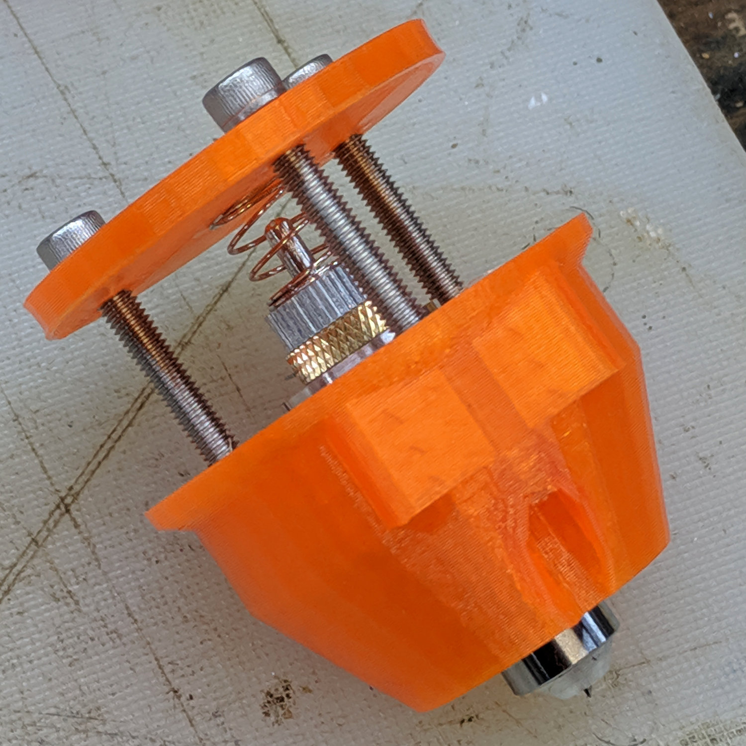
The Smell of Molten Projects in the Morning

Ed Nisley's Blog: Shop notes, electronics, firmware, machinery, 3D printing, laser cuttery, and curiosities. Contents: 100% human thinking, 0% AI slop.

Category: Machine Shop

Mechanical widgetry

  • Mini-Lathe Cut-Off Tool Holder: Improved Clamp Screw

    Apparently all mini-lathe cutoff tool holders suffer from the same problem:

    Lathe Cutoff Tool - OEM swaged screw
    Lathe Cutoff Tool – OEM swaged screw

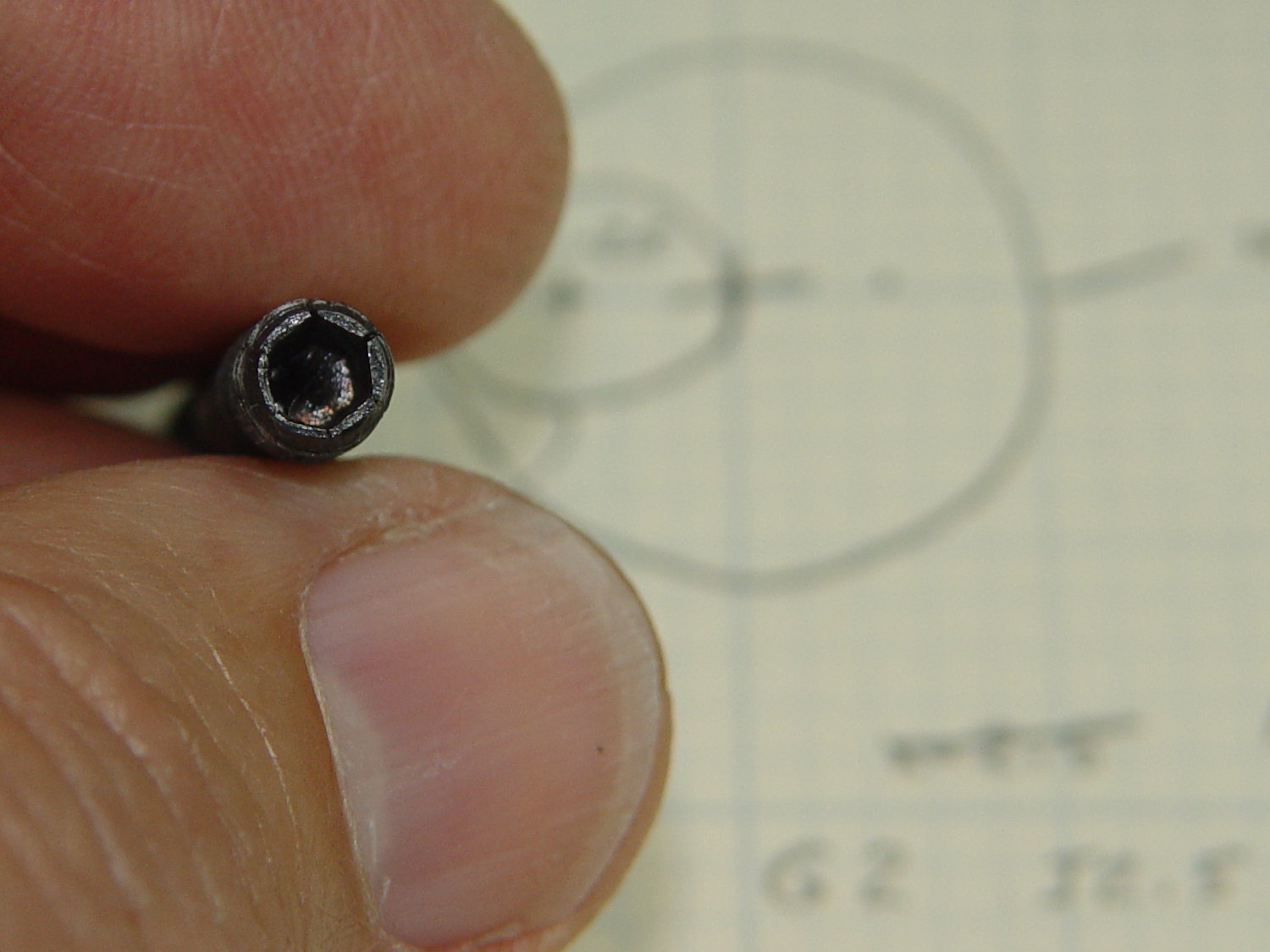
    The clamp tightening screw is made from butter-soft Chinese steel with a swaged hex socket. As you’d expect, the hex wrench eventually (as in, after a few dozen adjustments, tops) rips the guts right out of the socket.

    The screw has a M6×1.0 mm threads, but the thread around the hex recess is left-handed. While I could, in principle, print a 127 tooth change gear, rebuild the lathe’s banjo to accommodate it, then single-point a backassward M6 thread, it’s easier to just use a standard socket head cap screw:

    Lathe Cutoff Tool - rebuilt screw
    Lathe Cutoff Tool – rebuilt screw

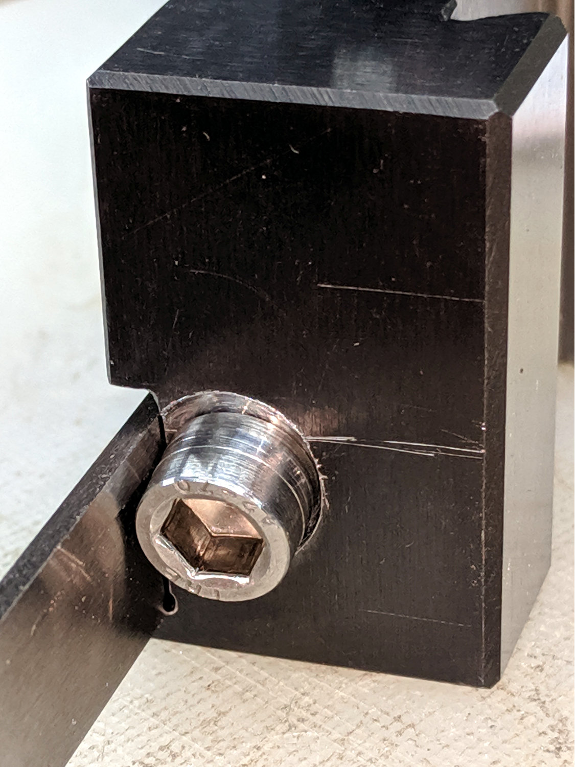
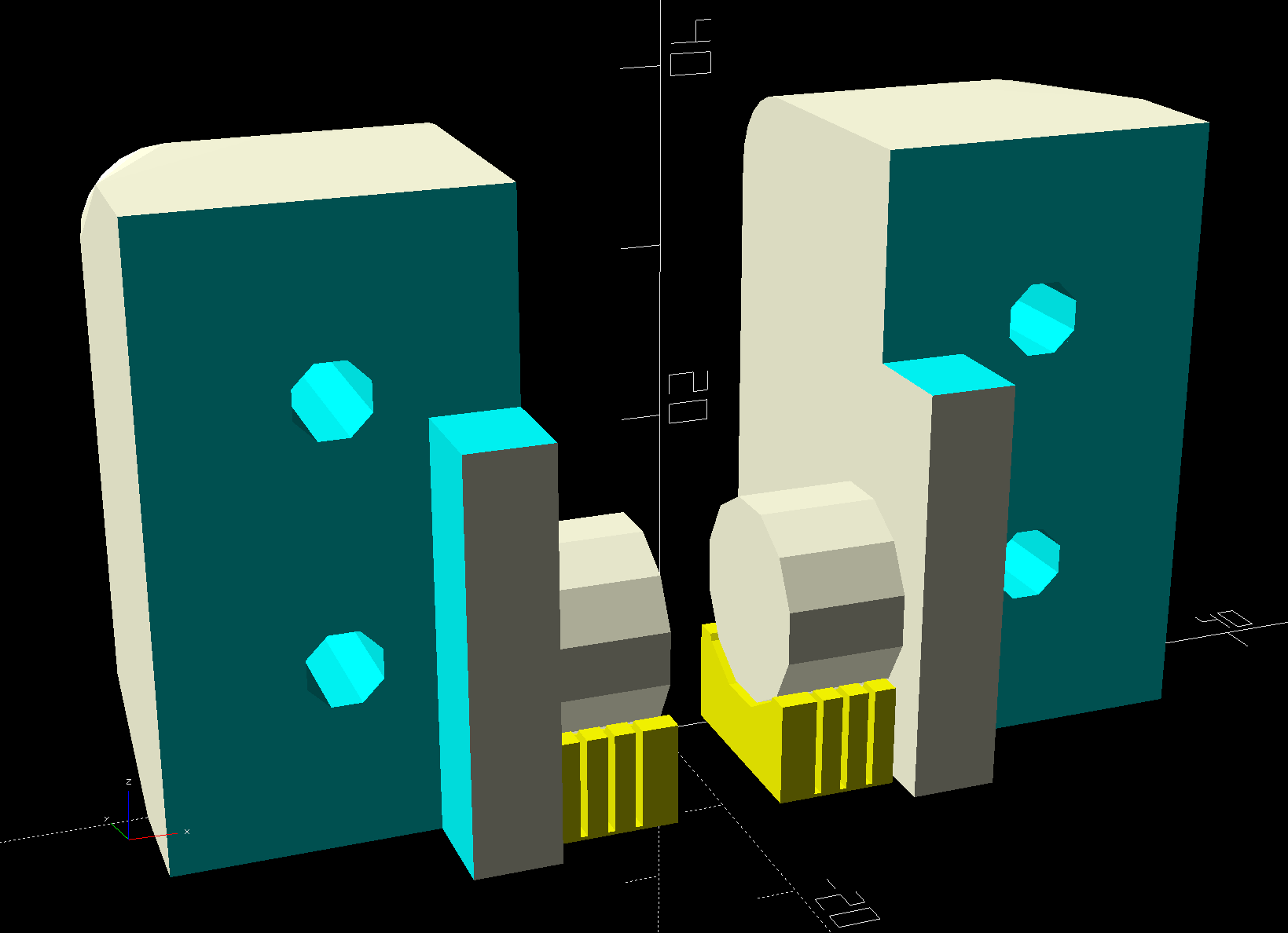
    The clamp screw passes through the block at an angle:

    Lathe Cutoff Tool - blade view
    Lathe Cutoff Tool – blade view

    Fortunately, the screw is perpendicular to the angled side over on the left, making it easy to clamp in the Sherline’s vise:

    Lathe Cutoff Tool - aligning to screw
    Lathe Cutoff Tool – aligning to screw

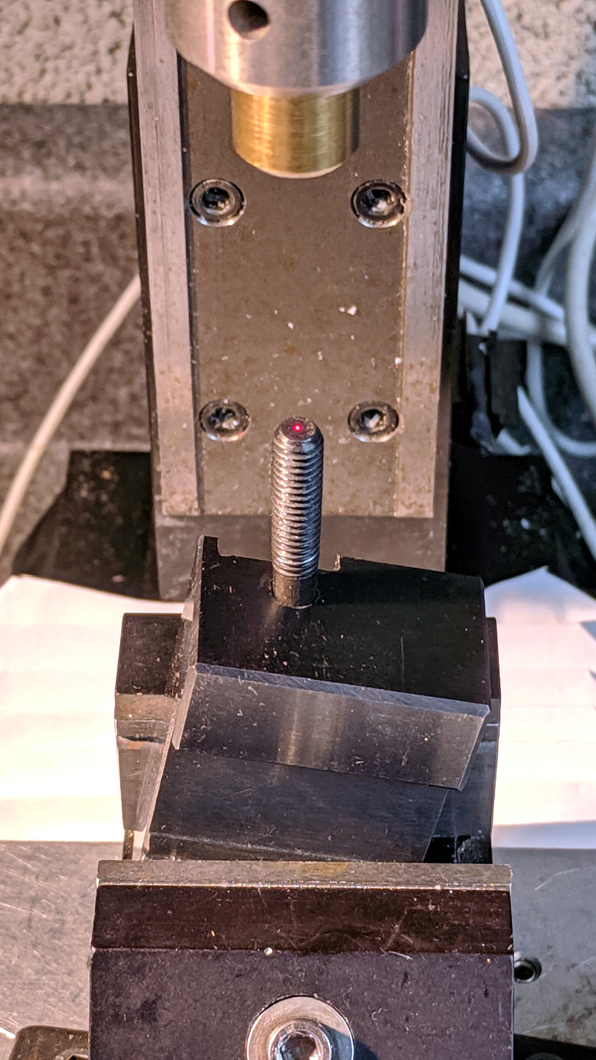
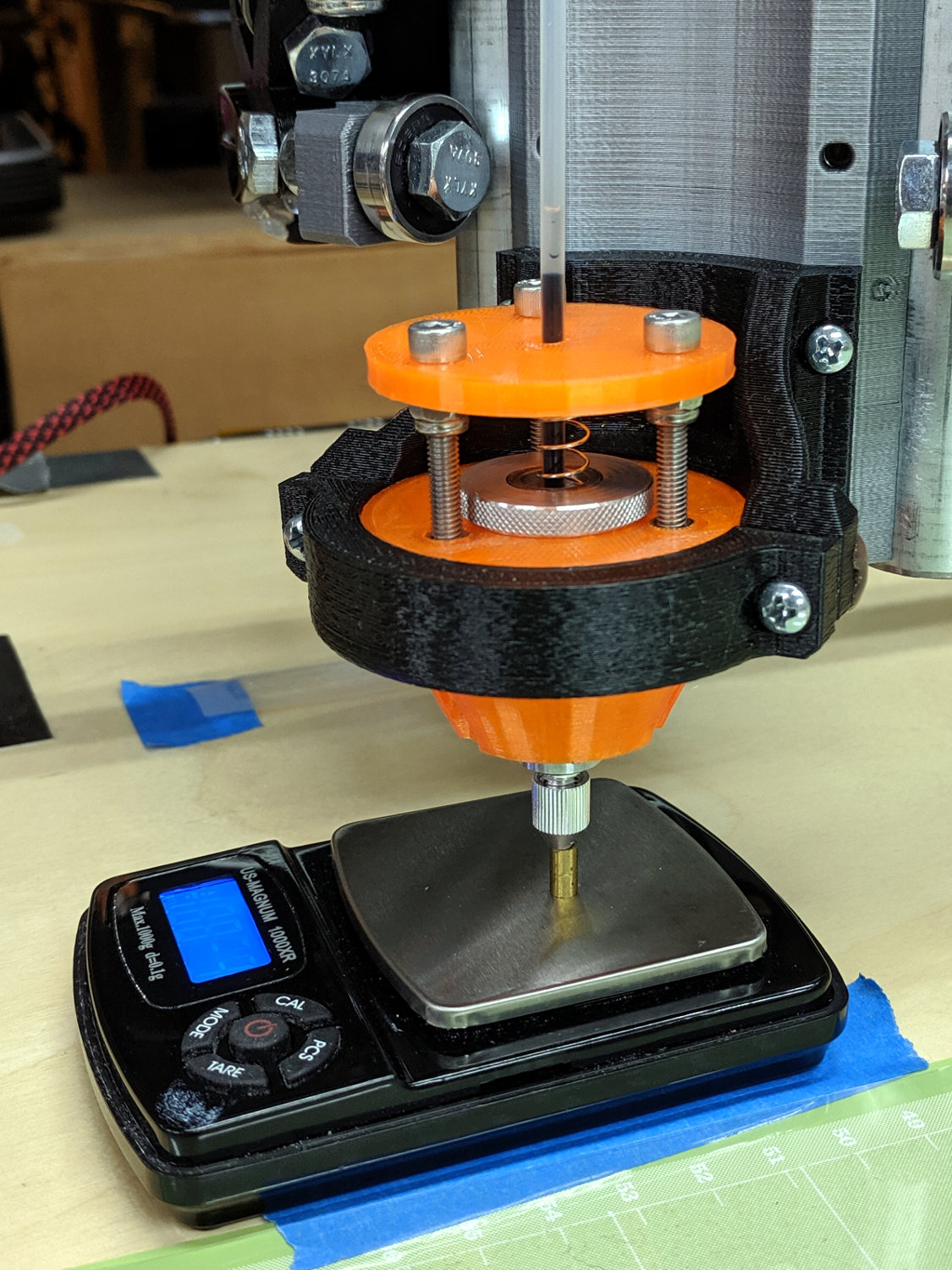
    Using the laser aligner seemed like a good idea at the time, but the top of the screw wasn’t particularly well-centered on the hole’s axis. I couldn’t screw the left-hand part (with the socket) in from the bottom and center the block near its surface, because then I couldn’t extract the screw before proceeding.

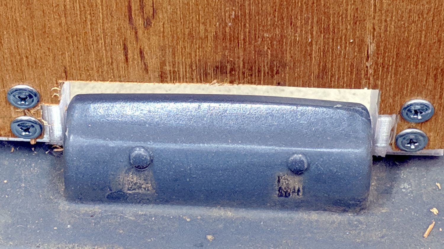
    I used a diamond burr to grind out a flat for the screw head:

    Lathe Cutoff Tool - clearing screw recess
    Lathe Cutoff Tool – clearing screw recess

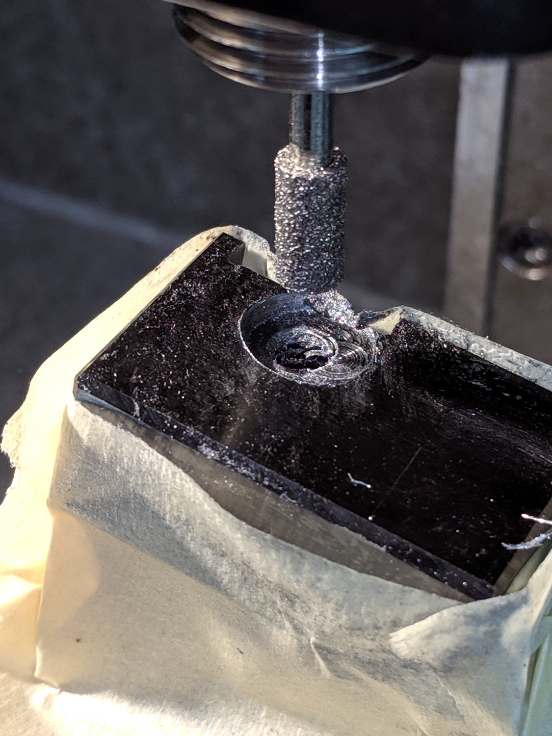
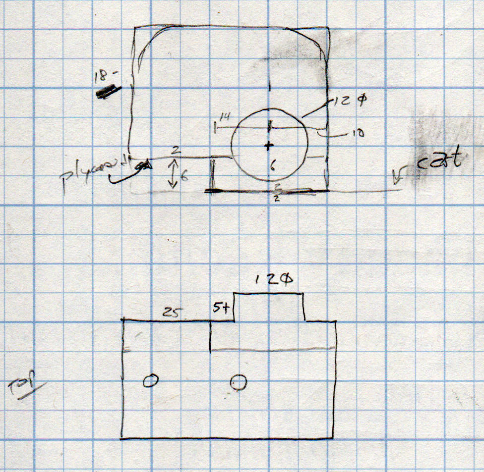
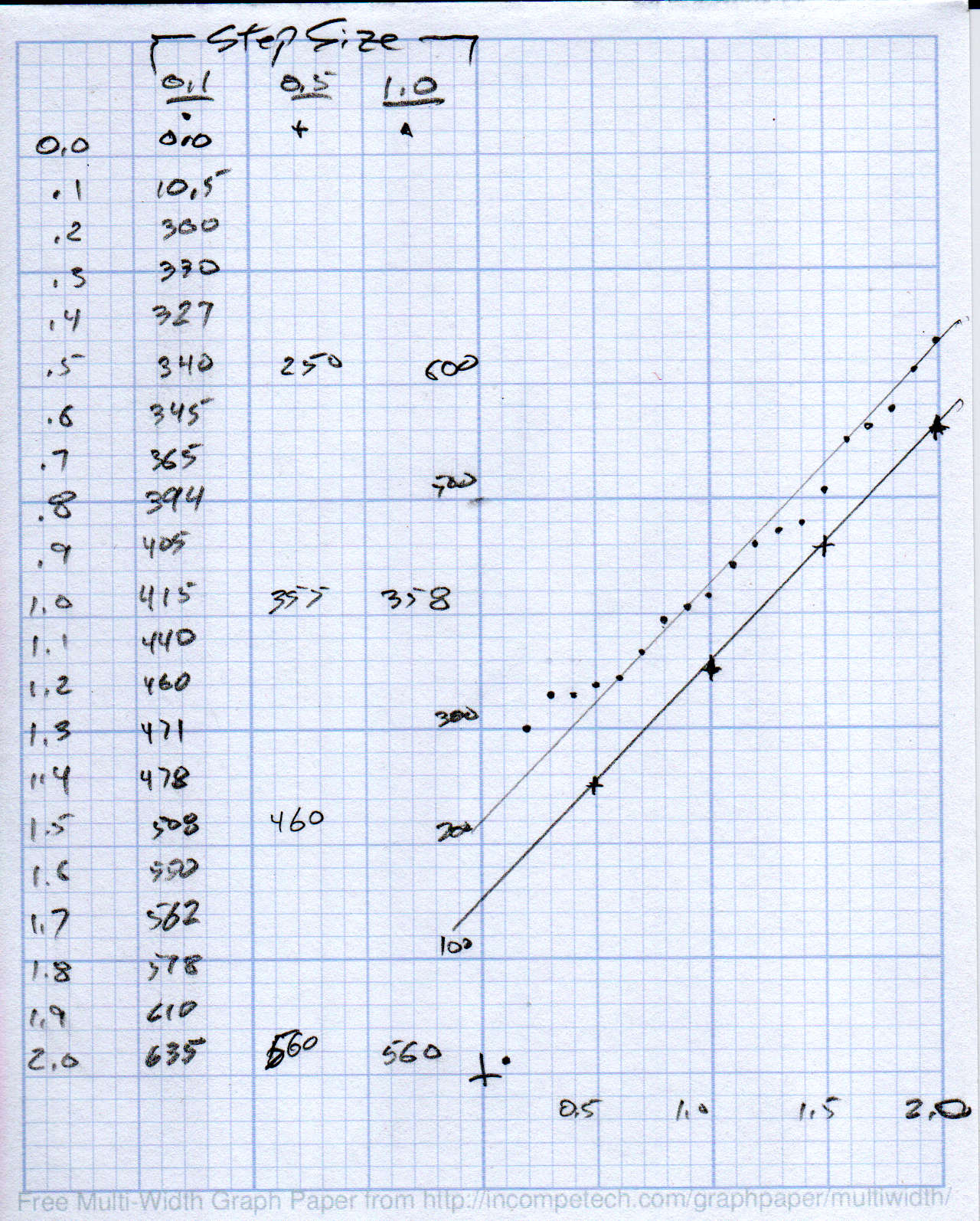
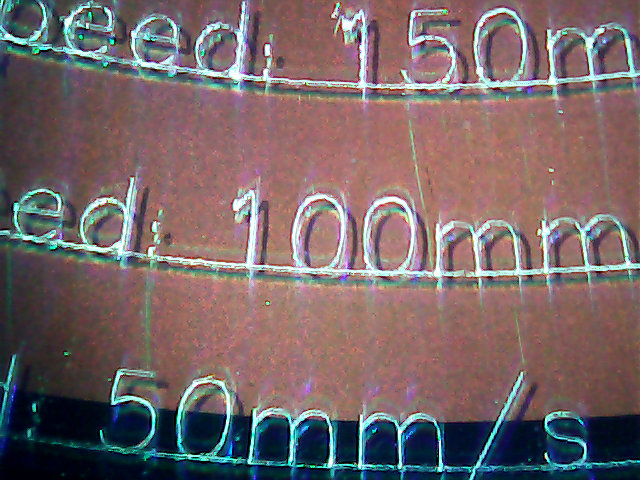
    The flat came from about twenty manual G2 I-2.5 full-circle passes, stepping down through the hard steel block 0.1 mm per pass, at a too-slow 4000 RPM and a too-fast 30 mm/min feed, with plenty of water squirted from one side into a shop vac snout on the other. The doodle in the background of the first picture shows a first pass at the layout, with the burr centered at X=-2.5; I actually did the grinding from X=+2.5 so most of the passes started in thin air.

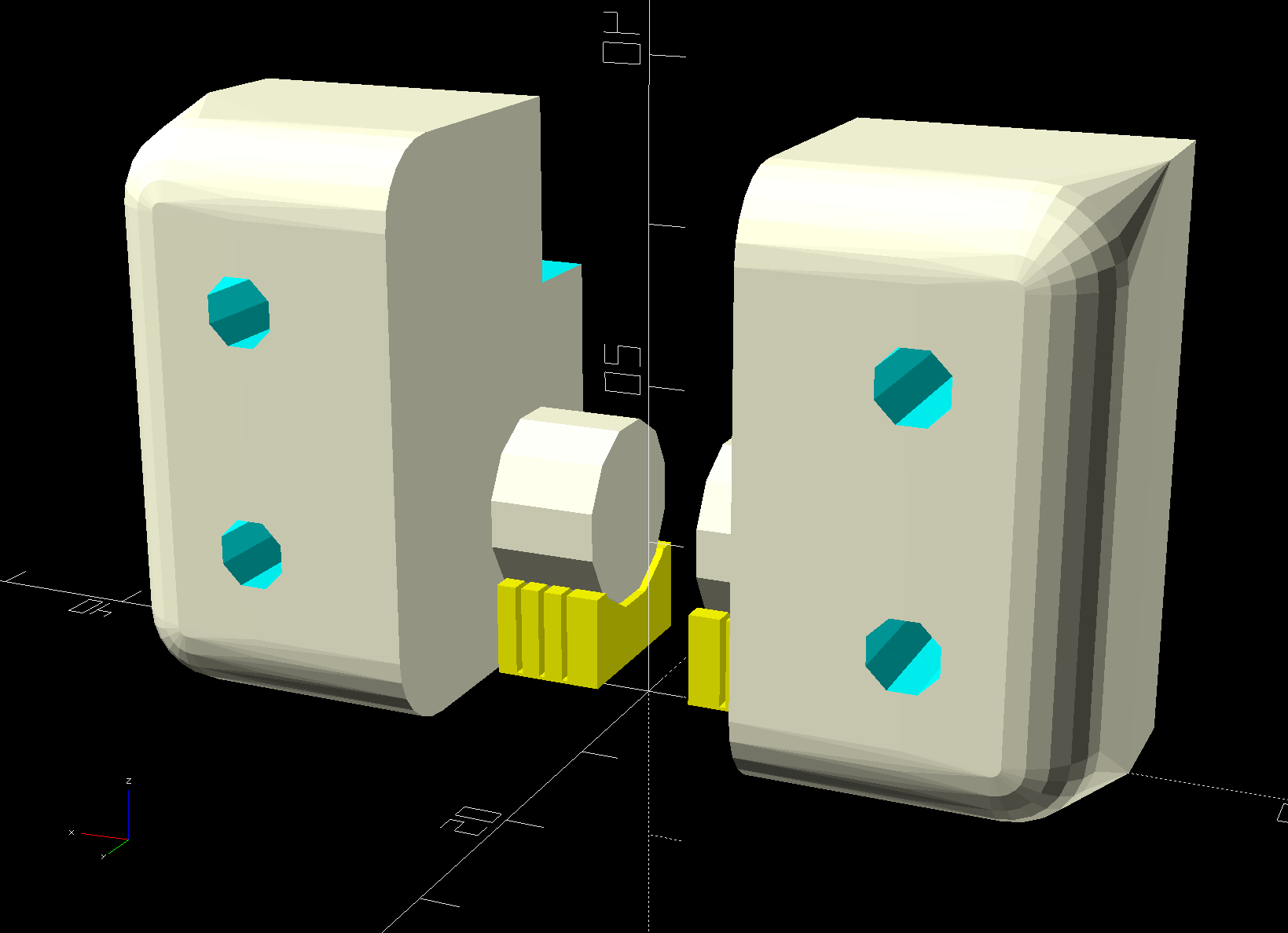
    The screw head started just shy of 10 mm OD and the burr just over 5.2 mm, so the ensuing 5 mm circles created a flat barely large enough. If the flat were perfectly centered on the screw axis, I wouldn’t have had to grind out another millimeter on the left side (toward the bottom of the tool holder body), but it worked out OK:

    Lathe Cutoff Tool - 6 mm SHCS test fit
    Lathe Cutoff Tool – 6 mm SHCS test fit

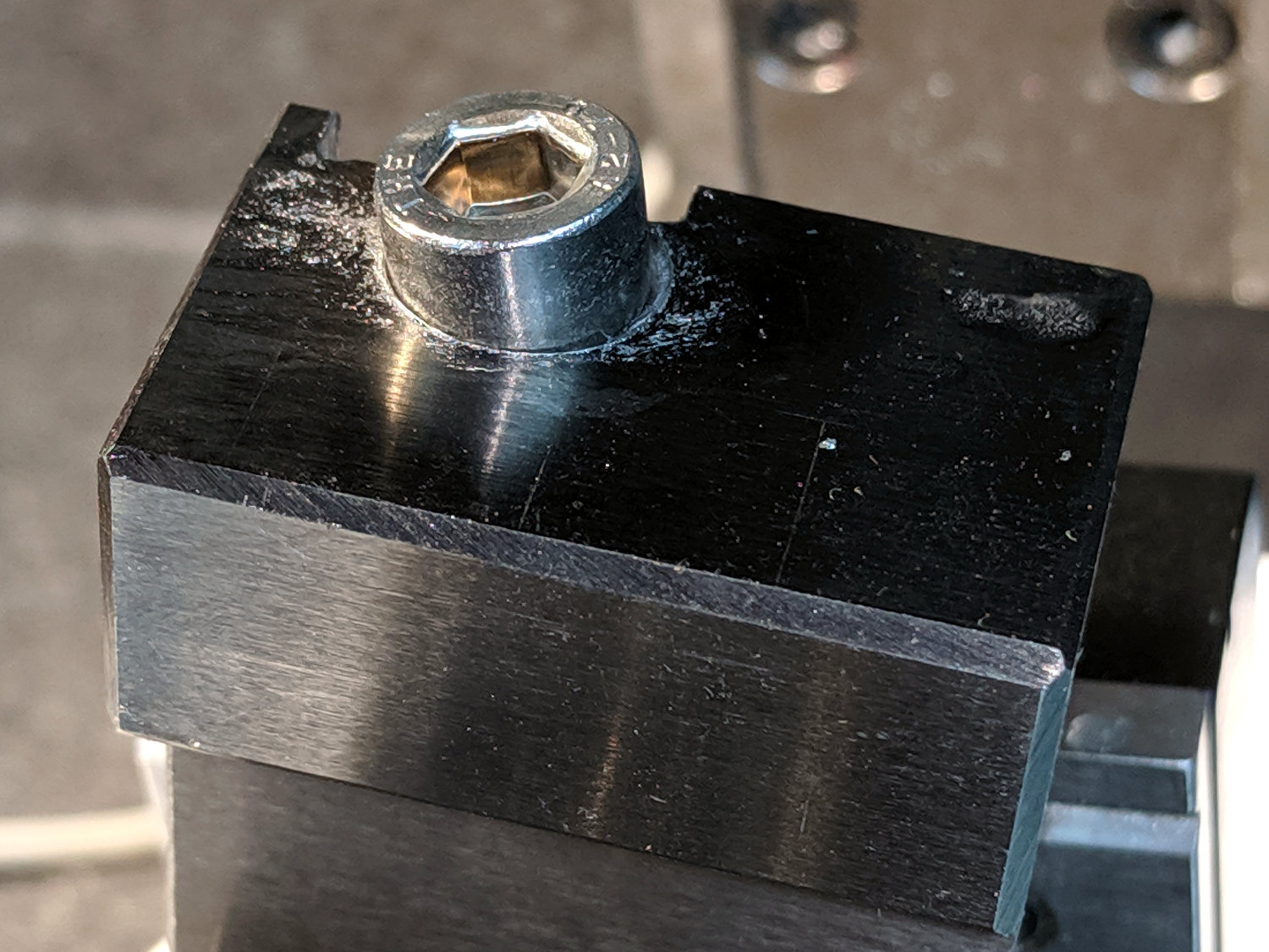
    The trial fitting also showed the head stuck out ever so slightly beyond the far side of the block, where it would interfere with the blade, so I turned off 0.4 mm off its OD.

    If I had a 50 mm SHCS in hand, I’d have used it. Instead, I extended the threads of a 75 mm screw, then lopped off the end to the proper length. I’ll spare you the ordeal, including the moment when I reached for the cutoff tool to shorten the screw. A bag of such screws will arrive shortly, in preparation for future need.

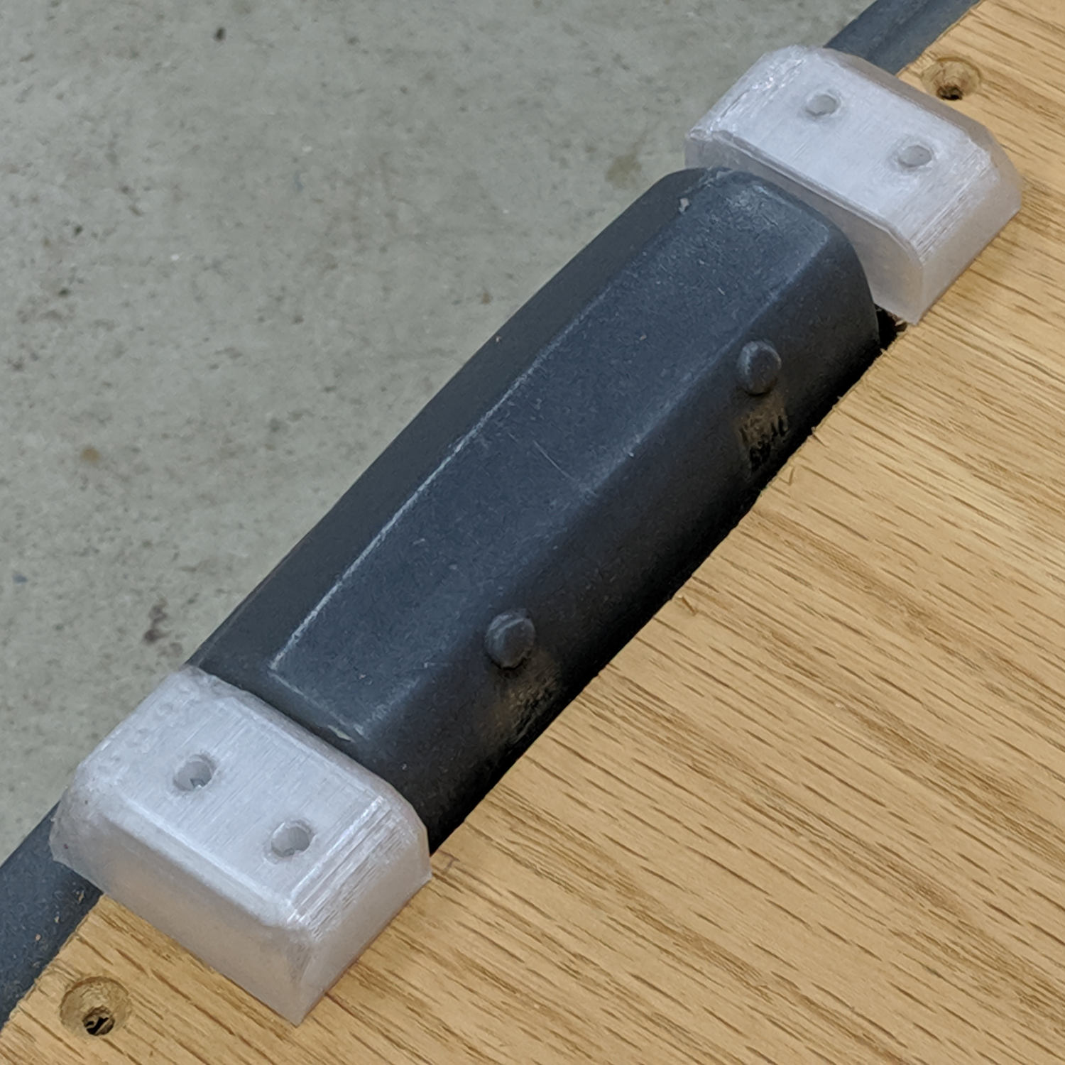
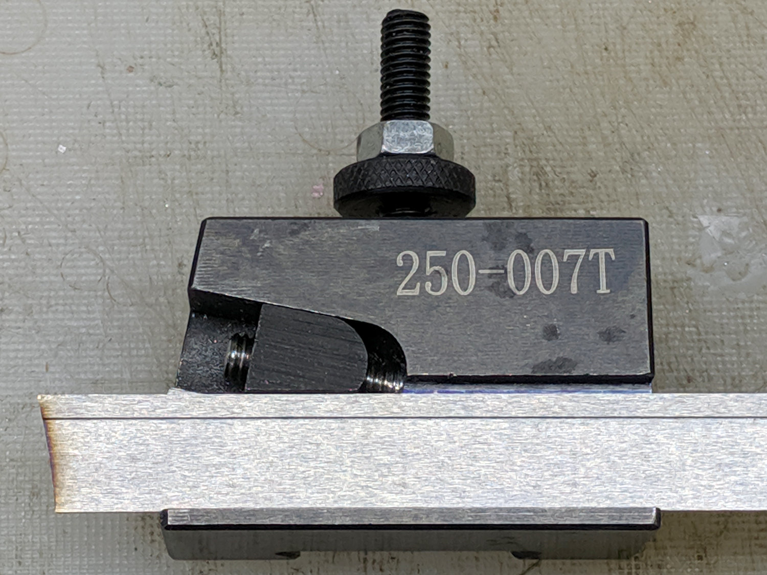
    Now the [deleted] cut-off holder works the way it should have from the beginning.

  • Mower FOD

    For reasons not relevant here, the lawn mower suffered some Foreign Object Damage:

    Lawn Mower - bent blade mount
    Lawn Mower – bent blade mount

    I’m sure the hard stop loosened the tolerances along the shaft, but the mower fired right up (with that new blade!) and has no more vibration than usual, despite the seriously bent blade mount.

    I no longer have a deep emotional attachment to lawn mowers, which is apparently common, as the label advises me there’s no need to change the oil:

    Mower Engine - never change the oil
    Mower Engine – never change the oil

    Drive it ’til it drops …

  • Step2 Garden Seat: Replacement Seat

    Step2 Garden Seat: Replacement Seat

    A pair of Step2 rolling garden seats (they have a new version) served in Mary’s gardens long enough to give their seat panels precarious cracks:

    Step2 Seat - OEM seat
    Step2 Seat – OEM seat

    The underside was giving way, too:

    Step2 Seat - cracks
    Step2 Seat – cracks

    We agreed the new seat could be much simpler, although it must still hinge upward, so I conjured a pair of hinges from the vasty digital deep:

    Rolling Cart Hinges - solid model - bottom
    Rolling Cart Hinges – solid model – bottom

    The woodpile disgorged a slab of 1/4 inch = 6 mm plywood (used in a defunct project) of just about the right size and we agreed a few holes wouldn’t be a problem for its projected ahem use case:

    Step2 Seat - assembled
    Step2 Seat – assembled

    The screw holes on the hinge tops will let me run machine screws all the way through, should that be necessary. So far, a quartet of self-tapping sheet metal (!) screws are holding firm.

    Rolling Cart Hinges - solid model - top
    Rolling Cart Hinges – solid model – top

    A closer look at the hinges in real life:

    Step2 Seat - top view
    Step2 Seat – top view

    The solid model now caps the holes; I can drill them out should the need arise.

    From the bottom:

    Step2 Seat - bottom view
    Step2 Seat – bottom view

    Three coats of white exterior paint make it blindingly bright in the sun, although we expect a week or two in the garden will knock the shine right off:

    Step2 Seat - painted
    Step2 Seat – painted

    After the first coat, I conjured a drying rack from a bamboo skewer, a cardboard flap, and some hot-melt glue:

    Step2 Seat - drying fixture
    Step2 Seat – drying fixture

    Three small scars on the seat bottom were deemed acceptable.

    The OpenSCAD source code as a GitHub Gist:

    // Hinge brackets for rolling garden stool
    // Ed Nisley – KE4ZNU – 2019-06
    Layout = "Build"; // [Block,Build,Show]
    Support = true;
    /* [Hidden] */
    ThreadThick = 0.20;
    ThreadWidth = 0.40;
    HoleWindage = 0.2;
    Protrusion = 0.1; // make holes end cleanly
    ID = 0;
    OD = 1;
    LENGTH = 2;
    //———————-
    // Dimensions
    SeatThick = 6.0; // seat panel above cart body
    HingePin = [11.5,12.0,7.0]; // ID = tip OD = base
    HingeOffset = 8.0; // hinge axis above cart body (larger than radius!)
    HingeBolster = [5.0,24.0,SeatThick]; // backing block below hinge
    Block = [25.0,HingeOffset + 30.0,23.0]; // Z = above cart body
    Screw = [3.8,11.0,2.5]; // self-tapping #8 OD=head LENGTH=head thickness
    ScrewOC = 15.0; // spacing > greater than head OD
    ScrewOffset = Block.y/2 – (ScrewOC/2 + Screw[OD]/2 + HingeOffset); // space for head behind hinge
    BlockRadius = 7.0; // corner rounding
    //———————-
    // Useful routines
    module PolyCyl(Dia,Height,ForceSides=0) { // based on nophead's polyholes
    Sides = (ForceSides != 0) ? ForceSides : (ceil(Dia) + 2);
    FixDia = Dia / cos(180/Sides);
    cylinder(r=(FixDia + HoleWindage)/2,
    h=Height,
    $fn=Sides);
    }
    // Basic block shape
    // X axis collinear with hinge axes, hinge base at X=0
    module HingeBlock() {
    PinSides = 3*4;
    PinSupport = [HingePin[LENGTH] – 2*ThreadWidth,0.6*HingeOffset,HingePin[OD]]; // pre-rotated
    union() {
    translate([Protrusion,Block.y/2 – HingeOffset,HingeOffset])
    rotate([0,-90,0])
    rotate(180/PinSides)
    cylinder(d=HingePin[OD],h=HingePin[LENGTH] + Protrusion,$fn=PinSides);
    difference() {
    hull() {
    translate([Block.x – BlockRadius,-(Block.y/2 – BlockRadius),Block.z – BlockRadius])
    rotate(180/PinSides)
    sphere(r=BlockRadius/cos(180/PinSides),$fn=PinSides);
    translate([0,-(Block.y/2 – BlockRadius),Block.z – BlockRadius])
    rotate([0,90,0]) rotate(180/PinSides)
    cylinder(r=BlockRadius/cos(180/PinSides),h=Block.x/2,$fn=PinSides);
    translate([Block.x – BlockRadius,(Block.y/2 – BlockRadius),Block.z – BlockRadius])
    sphere(r=BlockRadius/cos(180/PinSides),$fn=PinSides);
    translate([0,(Block.y/2 – BlockRadius),Block.z – BlockRadius])
    rotate([0,90,0]) rotate(180/PinSides)
    cylinder(r=BlockRadius/cos(180/PinSides),h=Block.x/2,$fn=PinSides);
    translate([0,-Block.y/2,0])
    cube([Block.x,Block.y – HingeOffset,Block.z/2],center=false);
    translate([0,Block.y/2 – HingeOffset,HingeOffset])
    rotate([0,90,0]) rotate(180/PinSides)
    cylinder(r=HingeOffset/cos(180/PinSides),h=Block.x,$fn=PinSides);
    }
    translate([Block.x/2 + HingeBolster.x,0,(SeatThick – Protrusion)/2])
    cube([Block.x,2*Block.y,SeatThick + Protrusion],center=true);
    translate([0,-HingeBolster.y,(SeatThick – Protrusion)/2])
    cube([3*Block.x,Block.y,SeatThick + Protrusion],center=true);
    for (j=[-1,1])
    translate([Block.x/2,j*ScrewOC/2 + ScrewOffset,-4*ThreadThick])
    rotate(180/8)
    PolyCyl(Screw[ID],Block.z,8);
    }
    }
    if (Support) { // totally ad-hoc
    color("Yellow") render(convexity=4)
    difference() {
    translate([-(PinSupport.x/2 + 2*ThreadWidth),Block.y/2 – PinSupport.y/2,HingeOffset])
    cube(PinSupport,center=true);
    translate([Protrusion,Block.y/2 – HingeOffset,HingeOffset])
    rotate([0,-90,0])
    rotate(180/PinSides)
    cylinder(d=HingePin[OD] + 2*ThreadThick,h=2*HingePin[LENGTH],$fn=PinSides);
    for (i=[-1:1])
    translate([i*4*ThreadWidth – HingePin[LENGTH]/2,
    Block.y/2 – (PinSupport.y + 1*ThreadThick),
    HingeOffset])
    cube([2*ThreadWidth,2*PinSupport.y,2*PinSupport.z],center=true);
    }
    }
    }
    module Blocks(Hand = "Left") {
    if (Hand == "Left")
    HingeBlock();
    else
    mirror([1,0,0])
    HingeBlock();
    }
    //- Build it
    if (Layout == "Block")
    HingeBlock();
    if (Layout == "Show") {
    translate([1.5*HingePin[LENGTH],0,0])
    Blocks("Left");
    translate([-1.5*HingePin[LENGTH],0,0])
    Blocks("Right");
    }
    if (Layout == "Build") {
    translate([0,-Block.z/2,Block.y/2])
    rotate([-90,0,0]) {
    translate([1.5*HingePin[LENGTH],0,0])
    Blocks("Left");
    translate([-1.5*HingePin[LENGTH],0,0])
    Blocks("Right");
    }
    }

    This original doodle gives the key dimensions, apart from the rounded rear edge required so the seat can pivot vertically upward:

    Cart Hinge - dimension doodle
    Cart Hinge – dimension doodle

    The second seat looks just like this one, so life is good …

  • MPCNC: Calculating Spring Rates

    Calculate the spring rates for the drag knife, diamond engraver, and collet pen holders by measuring the downforce every 0.5 mm (or so):

    LM12UU Collet Pen Holder - spring rate test
    LM12UU Collet Pen Holder – spring rate test

    Then plotting the data points and eyeballing a straight-line curve fit:

    MPCNC - Drag Knife Holder - spring constant
    MPCNC – Drag Knife Holder – spring constant

    Doing it on hard mode definitely has a certain old-school charm. The graph highlights mis-measured data and similar problems, because, if you don’t see a pretty nearly straight line, something’s gone awry.

    But we live in the future, so there’s an easier way:

    Droid48 - Spring Rate - Linear Fit coefficients
    Droid48 – Spring Rate – Linear Fit coefficients

    Well, OK, it’s the future as of the early 1990s, when HP introduced its HP 48 calculators. I’m using the Droid48 emulator on my ancient Google Pixel: living in the past, right here in the future.

    Start by firing up the STAT library (cyan arrow, then the 5 key), selecting Fit Data … from the dropdown list, then selecting the Linear Fit model:

    Droid48 - Spring Rate - Linear Fit screen
    Droid48 – Spring Rate – Linear Fit screen

    Then tap EDIT and enter the data in a tiny spreadsheet:

    Droid48 - Spring Rate - Linear Fit data
    Droid48 – Spring Rate – Linear Fit data

    My default “engineering mode” numeric display format doesn’t show well on the tiny screen. Tapping the WID→ key helps a bit, but shorter numbers would be better.

    With the data entered, set an X value and tap the PRED key to get the corresponding Y value:

    Droid48 - Spring Rate - Linear Fit prediction
    Droid48 – Spring Rate – Linear Fit prediction

    Tapping the OK button puts the line’s coefficients on the stack, as shown in the first picture. Write ’em on a strip of tape, stick to the top of the holder, and it’s all good:

    LM12UU Collet Pen Holder - test plot - overview
    LM12UU Collet Pen Holder – test plot – overview

    Works for me, anyhow.

    HP still has the HP 48g manuals online. The (unofficial) HP Museum has a page on the HP 48S. More than you want to know about the 48 series.

  • MPCNC: Diamond Drag Engraving Speed Tests

    The MPCNC isn’t the most stable of CNC machine tools, given its large masses and 3D printed structure. My early plotting pen tests suggested speeds around 250 mm/min were appropriate:

    MPCNC - GCMC Text - 250 mm-min
    MPCNC – GCMC Text – 250 mm-min

    Diamond drag engraving produces a thinner line and makes the wobbulations more obvious:

    MPCNC Engraving Speed Test A - 600-900 mm-min
    MPCNC Engraving Speed Test A – 600-900 mm-min

    Another test showed similar results:

    MPCNC Engraving Speed Test B - 700-900 mm-min
    MPCNC Engraving Speed Test B – 700-900 mm-min

    Slowing down definitely reduces the shakes:

    MPCNC Engraving Speed Test B - 100-300 mm-min
    MPCNC Engraving Speed Test B – 100-300 mm-min

    Producing the best results takes quite a while:

    MPCNC Engraving Speed Test A - 50-200 mm-min
    MPCNC Engraving Speed Test A – 50-200 mm-min

    Similar results on another test:

    MPCNC Engraving Speed Test C - 50-150 mm-min
    MPCNC Engraving Speed Test C – 50-150 mm-min

    Those “mm/s” labels are typos; they should read “mm/min”. Plotting at -1.0 mm on scrap CDs and DVDs produces a downforce around 200 g.

    Eyeballometrically, 100 mm/min seems fine, but 50 mm/min (I’d likely use 60 for a nice round 1 mm/s) eliminates all the shakes.

    Smooth curves, like Guillloché patterns, can run much faster, because they don’t have abrupt direction changes. This 3-½ inch hard drive platter has text engraved at 100 mm/min and the pattern at 600 mm/min, both at -3.0 mm for 300 g of downforce:

    MPCNC Engraving - Guilloche drive platter test
    MPCNC Engraving – Guilloche drive platter test

    A closer look at the text:

    MPCNC Engraving - hard drive platter - detail A
    MPCNC Engraving – hard drive platter – detail A

    And some digits:

    MPCNC Engraving - hard drive platter - detail B
    MPCNC Engraving – hard drive platter – detail B

    When I want to brand an engraved CD, this will suffice:

    MPCNC Engraving - CD attribution text
    MPCNC Engraving – CD attribution text

    All in all, the MPCNC engraves much better than I expected!

  • Drag Knife Blade Ejector Handle

    The LM12UU drag knife holder buries the blade ejector pin deep inside the machinery:

    Drag Knife - LM12UU ground shaft - assembled
    Drag Knife – LM12UU ground shaft – assembled

    So a handle with a pin makes sense:

    LM12UU Drag Knife Ejector Pin Pusher
    LM12UU Drag Knife Ejector Pin Pusher

    It’s a variant Sherline tommy bar handle, so there’s not much to say about it.

    The dark butt end comes from the traces of the black filament I used for the previous part. Even after flushing half a meter of orange through the hot end, you’ll still see some contamination, even with the same type of plastic. Doesn’t make much difference here, though.

  • Power Lift Chair Upholstery Protection

    For reasons not relevant here, we have a power lift chair which has been shedding upholstery tufts since the day we got it. After realizing this wasn’t going to stop on its own, I spent a while poking around underneath and discovered the steel struts supporting the leg rest rub along the upholstery during their entire travel:

    Lift chair - strut vs upholstery
    Lift chair – strut vs upholstery

    Apparently, the padding behind the upholstery pushes it a bit further out than the original design could accommodate, letting the raw edges on the steel struts shave off the fuzz.

    I put relatively smooth stainless steel tape on all the protrusions and bent it around the rough edges:

    Lift chair - strut smoothing
    Lift chair – strut smoothing

    Those steel folds are smoother than they appear.

    It’s not obvious this will solve the problem, but the struts seems to be scraping off much less fuzz than before, so it’s a step in the right direction.

    Why is it all of today’s consumer products require 10% more engineering to work in the real world?