Ed Nisley's Blog: Shop notes, electronics, firmware, machinery, 3D printing, laser cuttery, and curiosities. Contents: 100% human thinking, 0% AI slop.
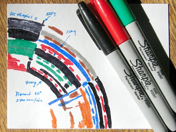
The “300 g” notation is wrong: the innermost scale is on the middle deck, which I engraved with 250 g of downforce, and reads through a window on the top deck. The next scale outward, the inner half of the green block on the left, would be on the upper deck at 300 g, just beyond the innermost scale.
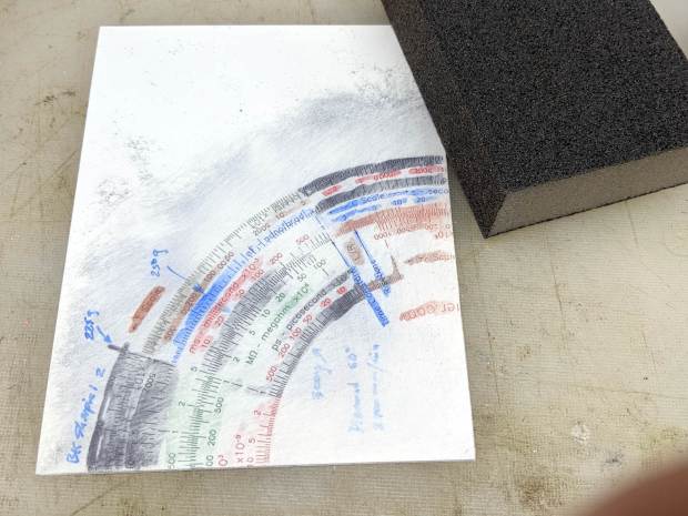
I removed the excess marker with a 320 (-ish) grit abrasive sanding block, producing a remarkable amount of gray dust in the process:
Diamond on styrene B – sanded
The general idea was to find out what the colors looked like when confined to narrow engraved slots:
Engraving Testpiece B – Sharpie colors – 2×600 dpi
It’s enlarged a factor of two from the 600 dpi scanned image by the simple expedient of changing it to 300 dpi, then assuming all the downstream image handling will Do The Right Thing, which could happen.
I sanded it before fully appreciating how even the smallest particle of crud under the styrene sheet ruins the result:
Engraving Testpiece B – debris oversanding
In this section, the scale with green numbers and black ticks was engraved at 300 g and is slightly less abraded than the adjacent scale at 225 g. Guesstimating the depth at 0.13 mm, 0.15 mm at most, the sanding block doesn’t remove much plastic at all … just enough to remove the scales.
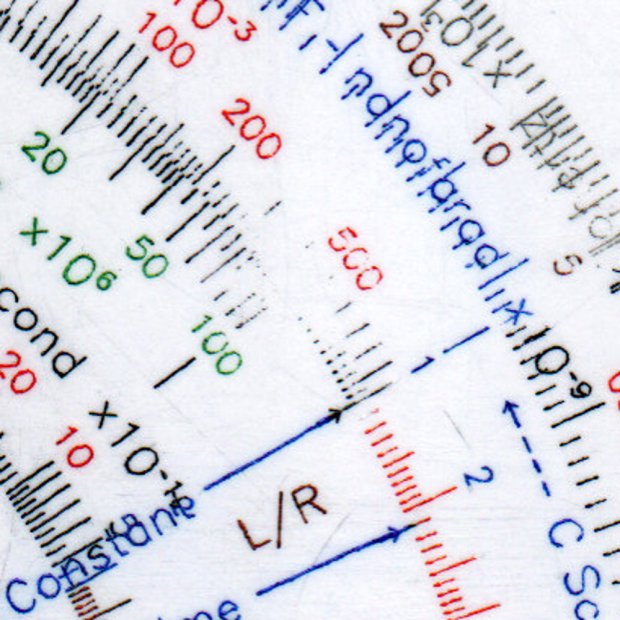
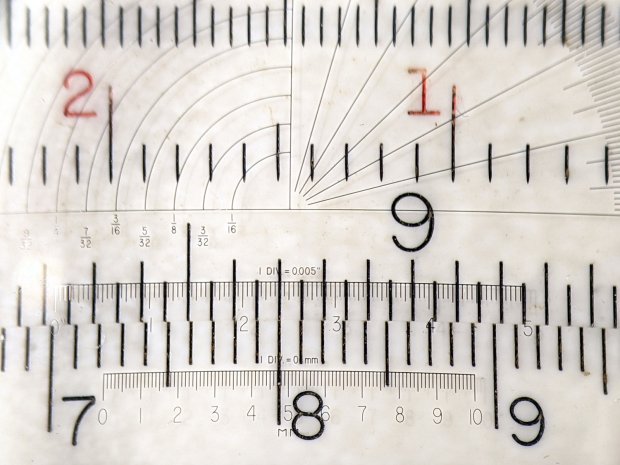
The lines are all about 0.1 mm wide and, to the naked eyeball, look about the same as the lines on my K&E Deci-Lon slipstick:, done on a real production line with an actual engraving tool and somebody who knew what he (I’m sure) was doing:
KE Deci-Lon Slide Rule – scale detail
The red CI scale reads right-to-left and, under magnification, you can see where the red ink made its way into the adjacent tick marks. I doubt they were using a pen, but it might be a mechanized roller or dauber.
All in all, sanding works, but it’s messy and poorly controlled.
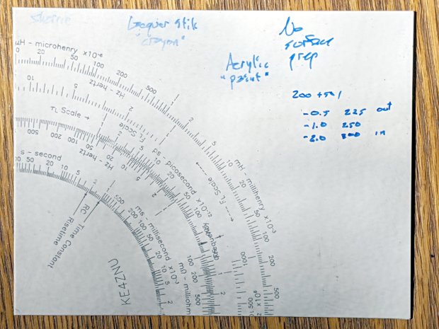
I covered one quarter with good old black Sharpie, a lacquer crayon, and well-aged black acrylic wall paint:
Diamond on styrene – engraving test – raw color fill
Applying a sanding block removed the rubble + scribbles and brought the surface down to the engraved patterns:
Diamond on styrene – engraving test – 225 250 300g 2400mm-min
The lacquer crayon doesn’t seem to adhere well to styrene:
Diamond on styrene – 225 250 g 2400mm-min – lacquer crayon
A closer look shows I probably sanded off too much of the surface, perhaps above some grit below the sheet, because those lines almost vanish:
Diamond on styrene – 225 250 g 2400mm-min – lacquer crayon
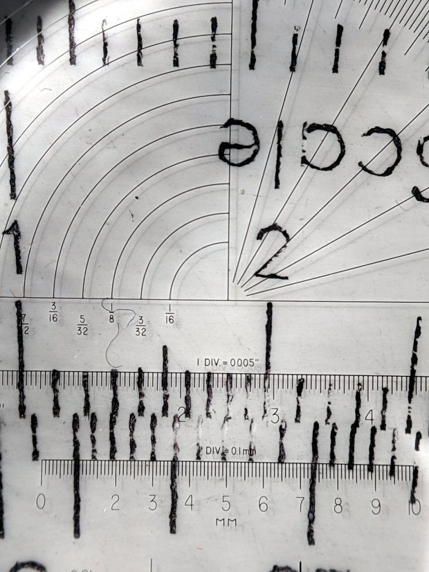
The crayon may adhere better to deeper lines. These are obviously too shallow and the pigment seems to come off in chunks:
Diamond on styrene – 300g 2400mm-min – lacquer crayon
The acrylic trim paint filled its patterns, despite having turned into a gummy mass during decades on the shelf:
Diamond on styrene – 225g 2400mm-min – acrylic paint
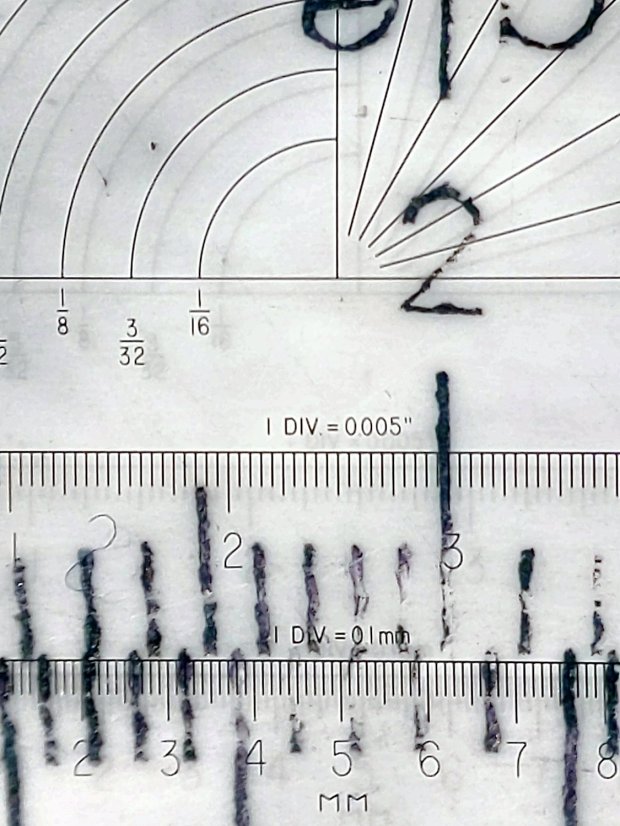
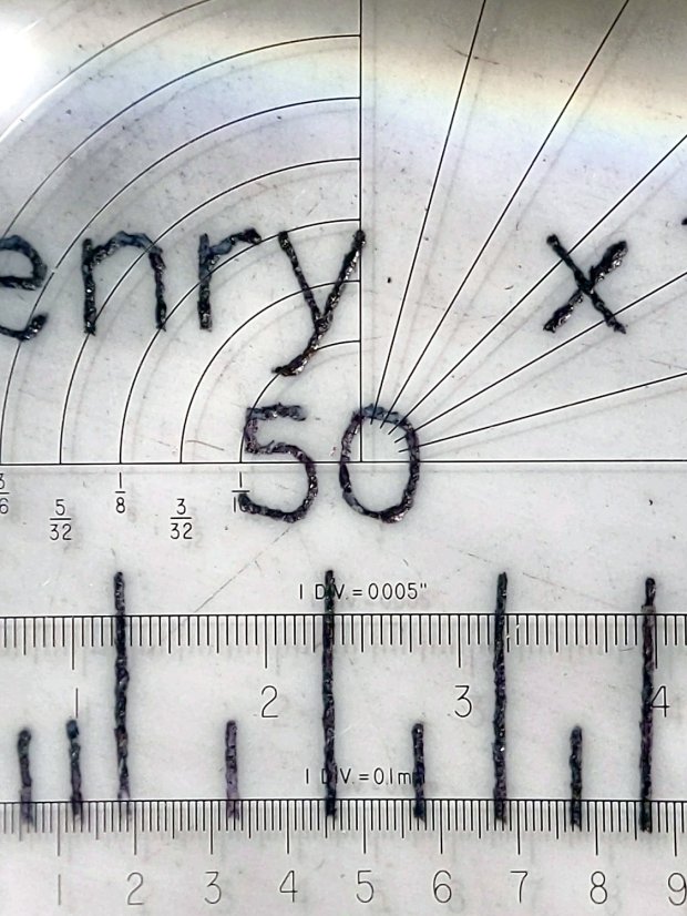
The Sharpie ink, being basically a thin liquid, completely filled its patterns and (apparently) soaked into the rough side walls. The lines seem to be 0.1 mm wide at 225 g downforce:
Diamond on styrene – 225g 2400mm-min – Sharpie
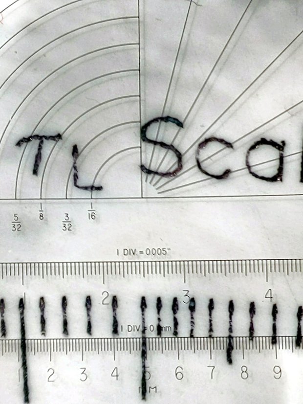
They’re less uniform at 250 g:
Diamond on styrene – 250g 2400mm-min – Sharpie
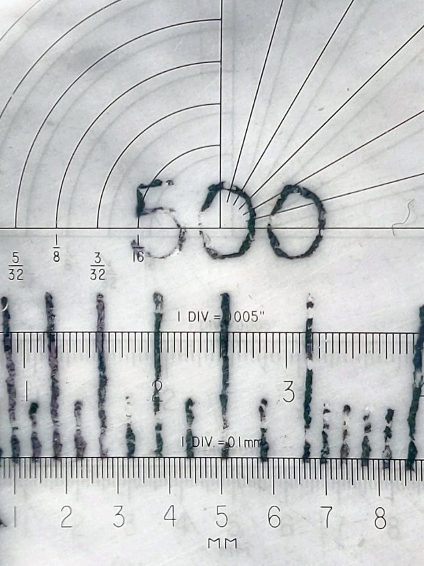
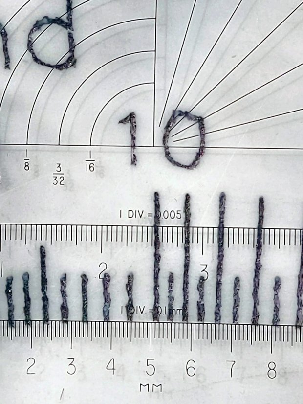
A 300 g downforce produces (somewhat) more uniform 0.15 mm wide lines and slightly distorted characters:
Diamond on styrene – 300g 2400mm-min – Sharpie
I have no way to measure the actual engraving depth. If the 60° diamond tool had a perfect point, which it definitely doesn’t, then a 0.15 mm wide trench would be 0.13 mm deep. I’ve obviously sanded off some of the surface, so those lines could be, at most, 0.1 mm deep.
All in all, the engraving came out better than I expected!
You’d hope the original owner would tape a key inside each file cabinet before donating it to charity; ours arrived unlocked and without keys. Fortunately, eBay sellers have All The Keys and I ordered replacement keys for each cabinet.
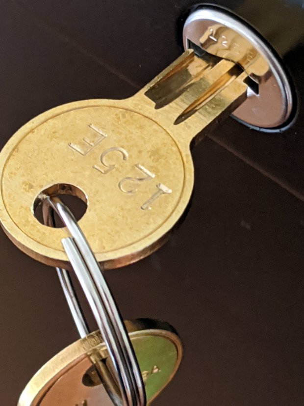
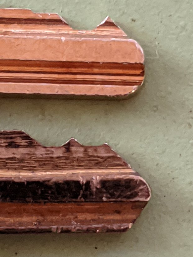
One pair of new keys fit into their lock, but the shoulder didn’t seat properly and the key didn’t turn:
HON Lateral File – 125E key insertion
Compared with a key for the other cabinet (on the bottom), it seems the tip profile wasn’t quite the same:
HON Lateral File – 125E key tip
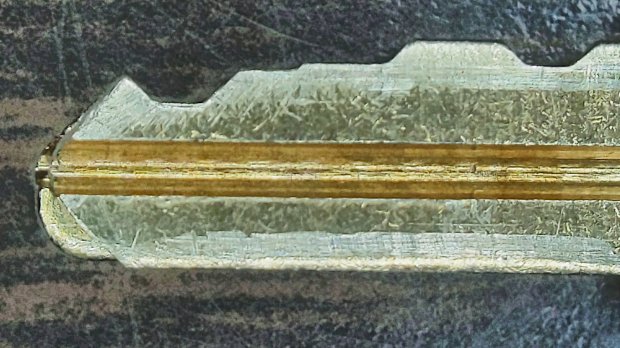
Perhaps the underside of the tip hadn’t been cut? Stacking the two keys makes it even more obvious:
Key 125E tip shaping – vs Key 101E
The eBay seller suggested the lock cores have changed over the years, as other (unaltered) keys fit current cabinet locks. Perhaps HON used fussy high-quality lock cores back in 2004 when they built these cabinets.
I gingerly filed the 125E key’s tip to match the 101E key and, after several iterations, the shoulder seated firmly in the lock and the core turned smoothly. Flushed with success, I marked the other key of the pair, filed to the mark, and it worked on the first try.
Mary doesn’t plan to store any secret fabrics in her new cabinets, but now I can declare victory and move on.
After sliding the HON Lateral File Cabinet shelf into place and installing the bumpers, it seemed rather loose and floppy. Comparing the situation with the other file cabinet showed it had a missing glide button in the rear and two missing slides at the front.
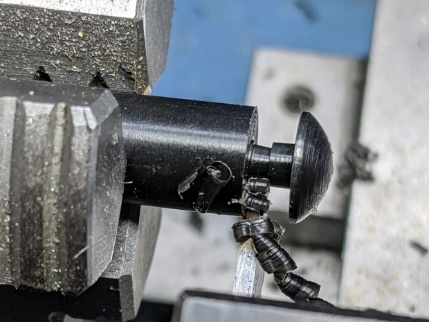
A replacement button emerged from the end of a Delrin rod:
HON Lateral File – shelf button – parting off
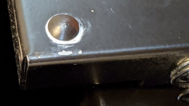
The original buttons had an expanding stem, which is easy to do with an injection-molded part. I opted for simple adhesive, with enough of a blob underneath the shelf to (presumably) lock it in place forevermore:
HON Lateral File – shelf button – installed
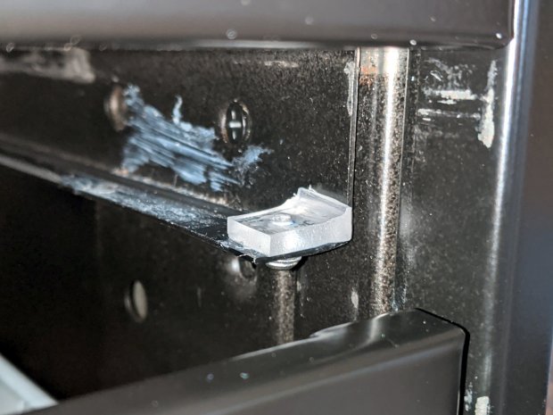
The slides required an iterative design technique (pronounced “fumbling around”), because nothing on either side remained square / plumb / true / unbent. I hacked the first version from scrap acrylic, broke off anything that didn’t fit, and got better measurements from what remained:
HON Lateral File – shelf front guide – size test
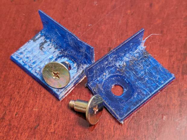
With those measurements in hand, the second version used a pair of weird flat-head shoulder screws (probably from a hard drive) to anchor 3D printed angle brackets into the frame:
HON Lateral File – shelf slides – version 2
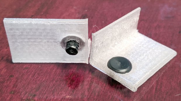
Those worked reasonably well, but PETG doesn’t produce a nice sliding surface, so the final version has flat-head Delrin studs in slightly tweaked brackets:
HON Lateral File – shelf slides – version 3
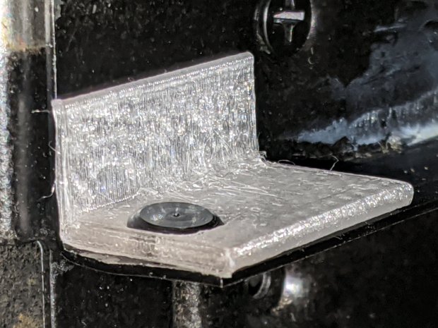
As with the buttons in the back, the original slides had expanding studs holding them in place, but glue works fine here, too:
HON Lateral File – shelf slides – version 3 – installed
The button isn’t quite square to the surface and the slide isn’t quite flush with the bent metal in the frame, but it’s Good Enough™ for a shelf that won’t get lots of mileage.
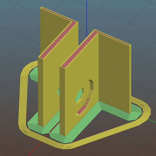
For reference, the brackets should print vertically to wrap the plastic threads around the upright for better strength:
HON Lateral File Shelf Slide – Slic3r
If you did it the obvious way, the upright side would break right off at the first insult from the hulking shelf, although they’re basically a solid chip of plastic, with a little infill inside the bottom slab.
While I was at it, I pulled the springs to make them a bit longer, so they touch the back of the frame when the shelf is half an inch behind the front face of the drawers. A firm push and those Delrin contact points let the shelf pop out an inch or so, with plenty of room for fingers underneath the front edge.
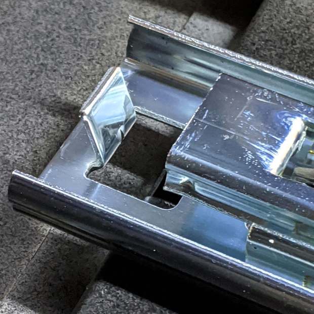
Some drawer slide stops near the back needed attention, too:
HON Lateral File – slide stop bumper – bent
I cannot imagine how hard somebody slammed the drawers, because bending the stops back to a right angle required a Vise-Grip and some muttering:
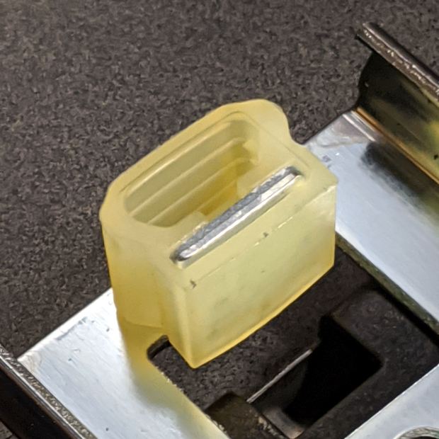
HON Lateral File – slide stop bumper
Oddly, the cushiony hollow side faces away from the drawer, toward the back of the frame, because putting it forward holds the drawer front proud of the front frame face. Maybe HON cost-reduced the steel slides by making them just slightly shorter and using the same bumpers?
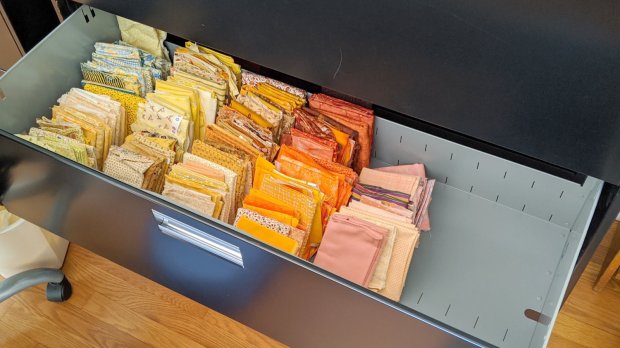
The drawers have begun filling up from boxes scattered around the house:
HON Lateral File – fabric stash
That’s the “orange” part of Mary’s collection, now with plenty of room to grow!
This file contains hidden or bidirectional Unicode text that may be interpreted or compiled differently than what appears below. To review, open the file in an editor that reveals hidden Unicode characters.
Learn more about bidirectional Unicode characters
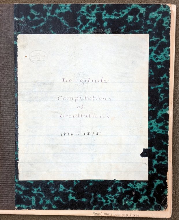
Mitchell 8.6 – Longitude computations of occultations 1872-1875
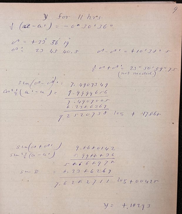
Here’s what “calculations” looked like in 1872:
Mitchell 8.6 p9 – Occultation of 1253 BAC at 11 hrs – calculation
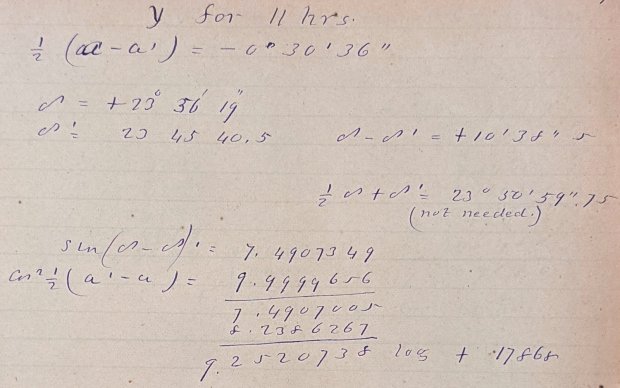
Yeah, grinding out trigonometry by hand using seven-place logarithms:
Mitchell 8.6 p9 – Occultation of 1253 BAC at 11 hrs – calculation detail 1
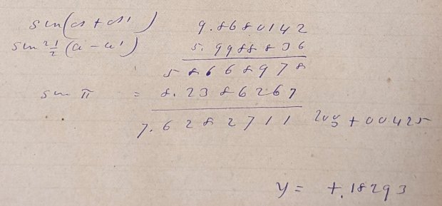
Not just by hand, but by hand with pen and ink:
Mitchell 8.6 p9 – Occultation of 1253 BAC at 11 hrs – calculation detail 2
Although you’ll find an occasional ink blot, she was probably using a fountain pen, rather than a dip pen, and made very few mistakes along the way. She often recorded direct instrument observations in pencil.
The next time you start pissing & moaning about how hard solid modeling is, suck it up.
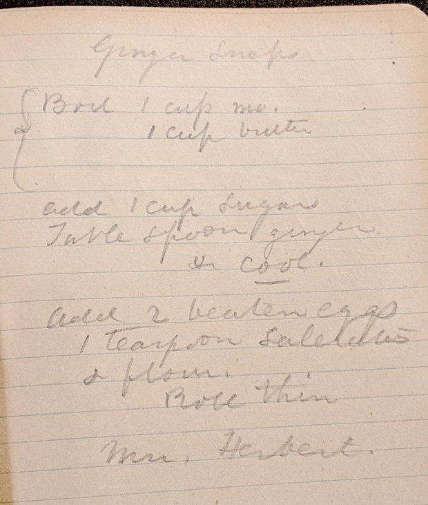
Bonus: a Ginger Snap recipe suggesting it wasn’t all toil & trouble in the observatory:
Mitchell 7.5 – Ginger Snap recipe
The mystery ingredient is saleratus, “aerated salt”, now known as baking soda; they used potassium bicarbonate before today’s sodium bicarbonate.
I fed all three of those G-Code files into bCNC, applied them to the same sheet with the same origin touchoff, and it worked fine.
The tool holder rate of 200 g + 50 g/mm produced downforces of 225, 250, and 300 g. In retrospect, the range wasn’t really broad enough, so Moah Force may be in order.
The diamond produced plenty of swarf:
Diamond on styrene – engraving test – swarf
Wiping the surface with a strip of masking tape clears away the loose rubble:
Diamond on styrene – engraving test – cleaned
The innermost scale comes from the top deck, engraved at 300 g. The long shadows from the plastic pushed up along the tick marks seem to indicate the deepest trenches, although I don’t have any way to measure their depth.
I scribed and snapped the sheet into quarters so I can (mis)treat the engraved patterns in various ways:
Diamond on styrene – engraving test – raw color fill