The Smell of Molten Projects in the Morning

Ed Nisley's Blog: Shop notes, electronics, firmware, machinery, 3D printing, laser cuttery, and curiosities. Contents: 100% human thinking, 0% AI slop.

Category: Machine Shop

Mechanical widgetry

  • HON Lateral File Cabinet Foot Repair

    HON Lateral File Cabinet Foot Repair

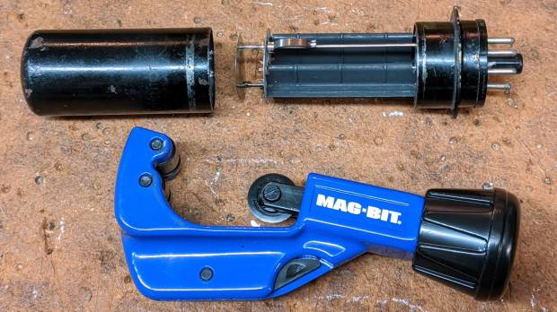
    We bought the best-looking (pronounced “least bashed”) pair of hulking five-drawer industrial-strength HON Brigade Lateral File Cabinets from the local ReStore outlet’s assortment for Mary’s quilting fabric stash. They came with a steep discount, barely fit inside the Forester, caused minor interior trim damage, and should organize her entire stash.

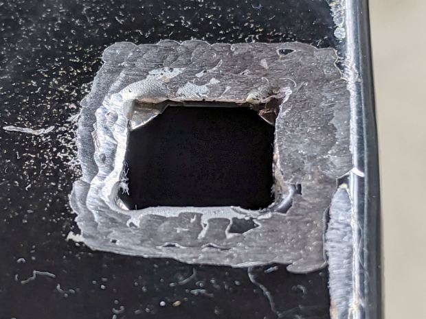
    One cabinet lost a foot nut at some point in its 16 year history:

    HON Lateral File - foot hole - weld nugget filed
    HON Lateral File – foot hole – weld nugget filed

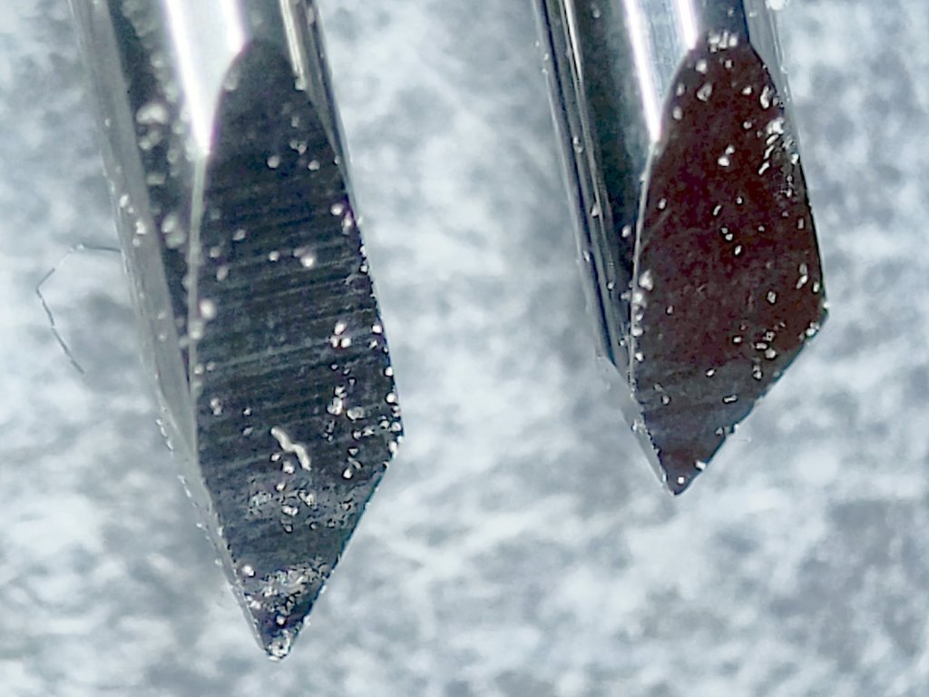
    The surviving foot nuts sported two weld nuggets apiece:

    HON Lateral File - OEM front foot
    HON Lateral File – OEM front foot

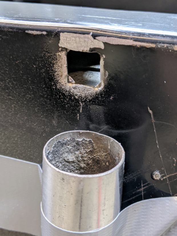
    The hole had the remains of one nugget at the top left and looks like a manufacturing defect to me. Of course, we’re (at least) the second owners and the usual lifetime warranty no longer applies.

    I can fix that.

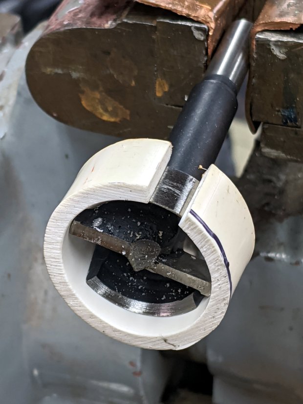
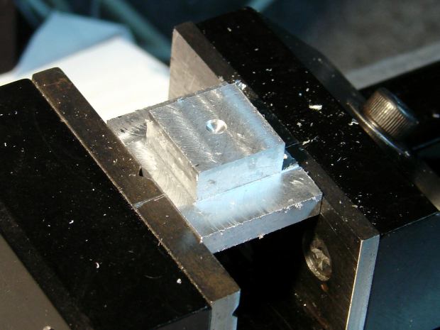
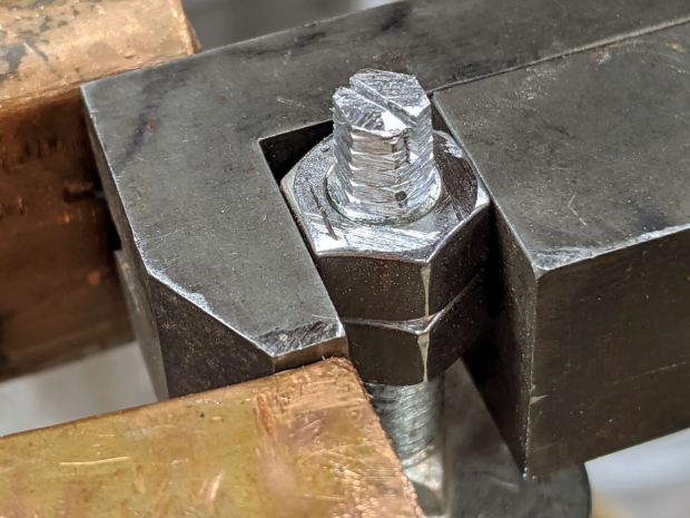
    Bandsaw a 1×¾ inch rectangle from 3/8 inch aluminum plate to match the surviving foot nut (which is steel, but aluminum will suffice for our needs). Break the edges, clamp in the Sherline, and mill a square protrusion to match the square-ish hole:

    HON Lateral File - square nut - rough cut
    HON Lateral File – square nut – rough cut

    Drill a 17/64 inch hole (looser than the nominal F drill, because I’m a sissy) for a flat-head bolt from the Drawer o’ 3/8-16 Bolts, tap, and clean up.

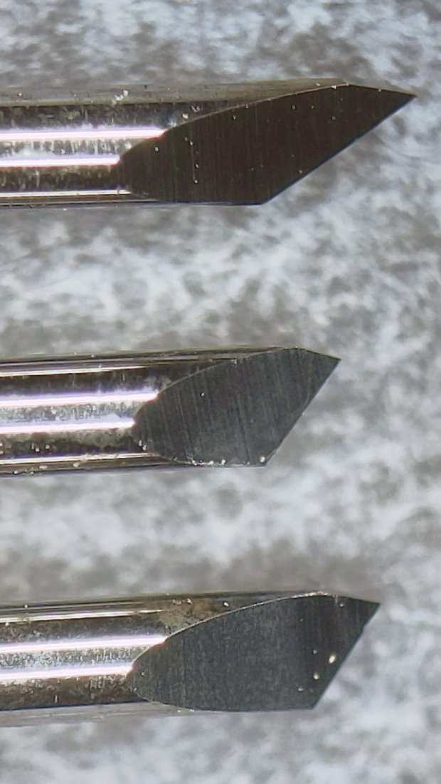
    A trial fit showed the nugget had to go before the nut would come even close to fitting flat into the hole:

    HON Lateral File - foot hole - grinding
    HON Lateral File – foot hole – grinding

    The sheet metal around the hole had absorbed at least one mighty blow pushing the entire surface inward behind the front edge. To compensate, recess the nut’s front edge and slope the sides with a Dremel wheel to let the bottom face sit level:

    HON Lateral File - square nut - taper grinding
    HON Lateral File – square nut – taper grinding

    Another trial fit showed the need for more recess:

    HON Lateral File - square nut - deeper cut
    HON Lateral File – square nut – deeper cut

    Another spate of grinding made it sit mostly level on the decidedly non-level surface around the hole:

    HON Lateral File - square nut - ready to install
    HON Lateral File – square nut – ready to install

    The beveled corners fit inside the swaged hole corners.

    Grind paint / crud off the sheet metal and roughen the surface for good epoxy griptivity:

    HON Lateral File - foot hole - ready for install
    HON Lateral File – foot hole – ready for install

    Stand the cabinet top-side-down to make the bottom level. I wish the basement had one more course of block, but it’s not to be.

    Butter the nut with JB Weld epoxy, plunk it in place, apply excess epoxy to make a fillet around the edges, apply duct tape to guy the top of the bolt level-ish, and let it cure:

    HON Lateral File - square nut - epoxy curing
    HON Lateral File – square nut – epoxy curing

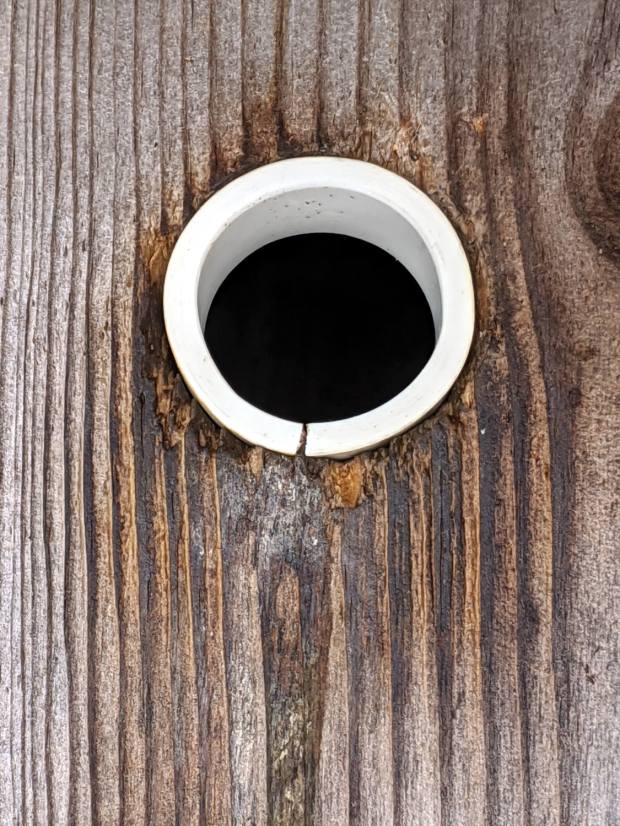
    After the epoxy stiffened enough to hold its position, remove the bolt, file a crude ¼ inch hex, and saw a screwdriver slot to make it match the other feet:

    HON Lateral File - new foot hex head
    HON Lateral File – new foot hex head

    Not the fanciest job I’ve ever done, but it now behaves just like the other ones and it’s all good. The HON Storage Files FAQ points to a Troubleshooting Guide showing how to level the thing with a hex socket from inside the bottom drawer.

    The flat heads on those bolts are basically 25 mm OD steel plates calling for fuzzy felt bumpers on the Sewing Room’s wood floors. When properly leveled, the front will be ⅛ inch higher than the rear. Although they suggest a pencil should roll toward the back, the top sheet metal on this one may be sufficiently warped to confuse the issue; I have a long level well suited to the task.

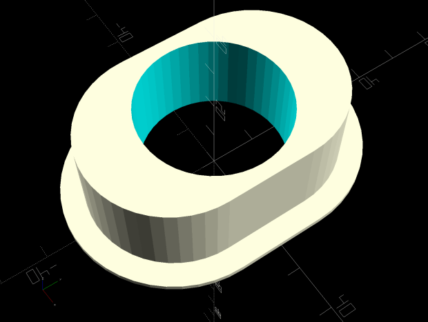
    The original dimension doodle includes metric offsets for cutting with a ¼ inch end mill:

    HON Foot nut - dimension doodles
    HON Foot nut – dimension doodles

    All in all, a satisfying day in the Basement Shop …

  • Drag Knife Blade Wear

    Drag Knife Blade Wear

    Having used the same two drag knife blades intermittently over the last three-ish years, I wondered just how worn they’d gotten:

    Drag Knife Blades - sides
    Drag Knife Blades – sides

    For scale, the cylindrical part of the blade is 1.0 mm OD.

    The blade with the longer face (left above and bottom below) has seen the most use and is definitely rounded at the tip:

    Drag Knife Blades - tips
    Drag Knife Blades – tips

    Three unused blades have sharp tips:

    Drag Knife Blades - unused 60 45 30 degree
    Drag Knife Blades – unused 60 45 30 degree

    From the top, the (nominal) blade angles are 60°, 45°, and 30°, generally indicated by yellow, red, and blue plastic caps. However, various eBay sellers disagree on how to measure the angle (up from surface / outward from axis) and which cap colors correspond to which angles.

    The unused 45° blade bracketed by the two used blades:

    Drag Knife Blades - unused in center
    Drag Knife Blades – unused in center

    The two lower blades have angles somewhere between 30° and 45°, suggesting slack grinder and QC tolerances. If the actual angle matters to you, buy an assortment (from one seller!), measure what you get, and don’t be surprised when the results aren’t anything in particular.

    Perhaps, with careful attention to alignment in a non-pivoting / collet holder, one might scribe exceedingly narrow lines.

    The microphotographic setup:

    Drag Knife Blades - microscope stage setup
    Drag Knife Blades – microscope stage setup

    That’s the back of a sheet of carbon paper (remember carbon paper?), which is deep dark gray in normal light. It’s sitting on the sheet of 100 mil grid paper providing scale for small objects, atop the microscope stage positioner, with cold white illumination from an LED ring light.

    Protip: even worn blades remain lethally sharp …

  • MPCNC: bCNC Probe Camera Refresh

    For the usual inscrutable reasons, updating bCNC killed the USB camera on the MPCNC, although it still worked fine with VLC. Rather than argue with it, I popped a more recent camera from the heap and stuck it onto the MPCNC central assembly:

    bCNC - USB probe camera - attachment
    bCNC – USB probe camera – attachment

    This one has a nice rectangular case, although the surface might be horrible silicone that turns to snot after a few years. The fancy silver snout rotates to focus the lens from a few millimeters to infinity … and beyond!

    If you think it looks a bit off-kilter, you’re absolutely right:

    bCNC - USB probe camera - off-axis alignment
    bCNC – USB probe camera – off-axis alignment

    The lens image reflected in a mirror on the platform shows the optical axis has nothing whatsoever to do with the camera case or lens snout:

    bCNC - USB probe camera - off-axis reflection
    bCNC – USB probe camera – off-axis reflection

    Remember, the mirror reflects the lens image back to itself only when the optical axis is perpendicular to the mirror. With the mirror flat on the platform, the lens must be directly above it.

    Because the MPCNC camera rides at a constant height over the platform, the actual focus & scale depends on the material thickness, but this should be typical:

    bCNC - USB Probe Camera - scale - screenshot
    bCNC – USB Probe Camera – scale – screenshot

    It set up a Tek Circuit Computer test deck within 0.2 mm and the other two within 0.1 mm, so it’s close enough.

    The image looks a whole lot better: cheap USB cameras just keep improving …

  • Bird Box Entrance Reducers: Round 2

    One of the bird box entrance reducers I installed nigh onto a decade ago is still on duty, although downy woodpeckers definitely want a larger hole:

    Bird Box - gray PVC pipe reducer - woodpecker damage
    Bird Box – gray PVC pipe reducer – woodpecker damage

    Another reducer had gone missing over the years, so I made one from a length of PVC pipe:

    Bird Box - PVC pipe reducer - shaping
    Bird Box – PVC pipe reducer – shaping

    It started as 1-½ PVC pipe, 1-⅞ inch actual OD and should fit into a 1-½ hole, so I measured 1.5 × 3.15 around the circumference, bandsawed out the excess, draped it over a 1-½ Forstner bit, toasted it with a heat gun, and squashed it so it’s just a little bit bigger than the (enlarged!) hole in the box.

    Now the entrance is 1-¼ (-ish), just like it should be:

    Bird Box - PVC pipe reducer - installed
    Bird Box – PVC pipe reducer – installed

    The bird box in the front yard has been attracting starlings, in addition to serving as a hawk perch:

    New Coopers Hawks - bird box takeoff whoops
    New Coopers Hawks – bird box takeoff whoops

    The oblong hole required advanced manufacturing techniques:

    Oval Entrance Reducer
    Oval Entrance Reducer

    The front face should be too slick for larger birds and the little ones will zip right into the hole:

    Bird Box - 3D printed entrance reducer
    Bird Box – 3D printed entrance reducer

    The two starlings who’d been evaluating the box seem to have moved on; we doubt they’re now homeless.

    The OpenSCAD source code as a GitHub Gist:

    // Bird Box – oval entrance reducer
    // Ed Nisley KE4ZNU 2020-02-12
    //- Extrusion parameters must match reality!
    // Print with 3 shells and 3 solid layers
    ThreadThick = 0.25;
    ThreadWidth = 0.40;
    HoleWindage = 0.2;
    function IntegerMultiple(Size,Unit) = Unit * ceil(Size / Unit);
    Protrusion = 0.1; // make holes end cleanly
    inch = 25.4;
    //———————-
    // Dimensions
    EntranceID = 1.25 * inch;
    BoxHole = [1.5,2.25] * inch;
    BoxWall = 0.75 * inch;
    HoleOC = BoxHole.y – BoxHole.x;
    FlangeWidth = 5.0;
    FlangeThick = 5*ThreadThick;
    $fn = 12*4;
    //——————-
    // Build it
    difference() {
    union() {
    linear_extrude(height=BoxWall + FlangeThick)
    hull()
    for (j=[-1,1])
    translate([0,j*HoleOC/2])
    circle(d=BoxHole.x);
    linear_extrude(height=FlangeThick)
    hull()
    for (j=[-1,1])
    translate([0,j*HoleOC/2])
    circle(d=BoxHole.x + 2*FlangeWidth);
    }
    translate([0,0,-Protrusion])
    cylinder(d=EntranceID,h=2*BoxWall);
    }

  • Slide Rules: Real Engraving vs. Pilot V5RT Pens

    A 0.5 mm Pilot V5RT pen produces good-looking results on presentation-grade paper:

    Tek CC - V5RT black - glossy presentation paper
    Tek CC – V5RT black – glossy presentation paper

    Peering through a measuring magnifier shows a bit more tremble in the traces, but they’re still OK:

    Tek CC - V5RT pen width
    Tek CC – V5RT pen width

    The desk light off to the upper left casts shadows from the reticle on the three different sheets.

    A closer view of the linear scales:

    Tek CC - V5RT pen width - detail
    Tek CC – V5RT pen width – detail

    The pen lines seem to be 0.25 to 0.3 mm wide, with 0.4 mm dots at the end of each stroke.

    For comparison, the engraved lines on my trusty K&E Deci-Lon slide rule are under 0.1 mm:

    KE Deci-Lon Slide Rule - scale detail
    KE Deci-Lon Slide Rule – scale detail

    The digits look like they’re embossed into the surface with shaped punches, rather than engraved like the lines. Of course, I don’t know how K&E’s production machinery worked.

    A closer view:

    KE Deci-Lon Slide Rule - scale detail - digits
    KE Deci-Lon Slide Rule – scale detail – digits

    I think 0.1 mm is an aggressively narrow trace width, even for a laser engraver.

  • Metal-case 5T4 Vacuum Tube Opened

    I’ve always wondered what’s inside a metal-case vacuum tube:

    Dual rectifier tube 5T4 - metal case opened
    Dual rectifier tube 5T4 – metal case opened

    The cutter last saw action on the EMT used in the MPCNC, so it’s intended for use on steel tubes. I thought about parting the case off in the lathe, but a tubing cutter sufficed for a first attempt, even if it couldn’t cut quite as close to the flange as I wanted.

    A 5T4 tube is a full-wave rectifier with two sections:

    Dual rectifier tube 5T4 - upright
    Dual rectifier tube 5T4 – upright

    Unsurprisingly, the guts resemble those of glass-envelope rectifier tubes in my collection, like this 5U4GB:

    5U4GB Full-wave vacuum rectifier - cyan red phase
    5U4GB Full-wave vacuum rectifier – cyan red phase

    The metal case would be far more rugged than a glass bottle and, perhaps, the flange locked the tube into its socket against vibration.

    The filaments surely weren’t thoriated, so it’s all good …

  • Filament Spool Sidewall

    A new spool of retina-burn orange PETG snagged when the takeup guide let the filament fall off the inboard side and the extruder tightened the loops around the spool holder. I carefully unwound the loops without removing the spool to ensure I didn’t introduce a crossover, scraped the bird’s next off the platform, and restarted the print.

    After undoing the second snag, I added a crude spool sidewall:

    Makergear M2 - filament spool sidewall
    Makergear M2 – filament spool sidewall

    It’s decidedly unlovely, but I was in a hurry to get a PCB holder printed and ready for use. Worked perfectly!

    I’ve rarely had a problem with any other spools and I don’t know what’s new-and-different with this one.