The Smell of Molten Projects in the Morning

Ed Nisley's Blog: Shop notes, electronics, firmware, machinery, 3D printing, laser cuttery, and curiosities. Contents: 100% human thinking, 0% AI slop.

Category: Electronics Workbench

Electrical & Electronic gadgets

  • Juki TL-2010Q: COB LED Light Bar

    Mary needed more light under the arm of her Juki TL-2010Q sewing machine, so I proposed a 12 V 6 W COB LED module instead of the high-density LED strips I used on her Kenmore 158s:

    Kenmore 158 Sewing Machine - Cool white LEDs - rear no flash
    Kenmore 158 Sewing Machine – Cool white LEDs – rear no flash

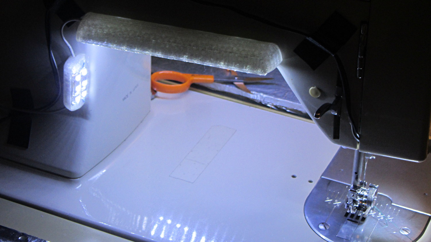
    Because the COB LEDs dissipate 6W, far more power than I’m comfortable dumping into a 3D printed structure, I redefined a length of aluminum shelf bracket extrusion to be a heatsink and epoxied the module’s aluminum back plate thereto:

    Juki TL-2010Q COB LED - test lighting
    Juki TL-2010Q COB LED – test lighting

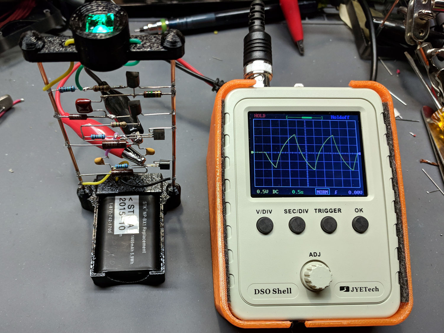
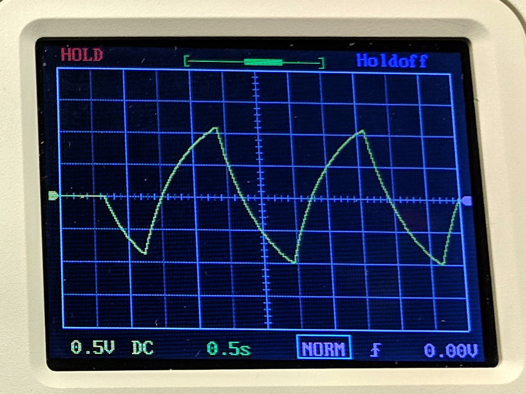
    Unlike the flexible LED strips, the COB LED modules have no internal ballast resistors and expect to run from a constant-current supply. Some preliminary testing showed we’d want less than the maximum possible light output, so a constant-voltage supply and a few ohms of ballast would suffice:

    Juki TL-2010Q COB LED - ballast resistor test
    Juki TL-2010Q COB LED – ballast resistor test

    With all that in hand, the heatsink extrusion cried out for smooth endcaps to control the wires and prevent snagging:

    TL-2010Q COB LED Light Bars - end caps - Show layout
    TL-2010Q COB LED Light Bars – end caps – Show layout

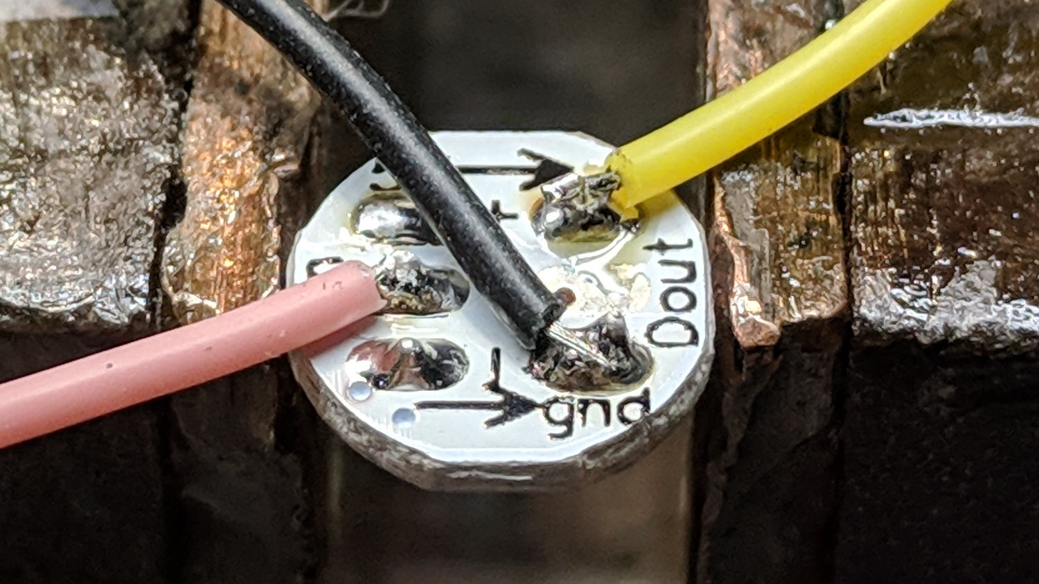
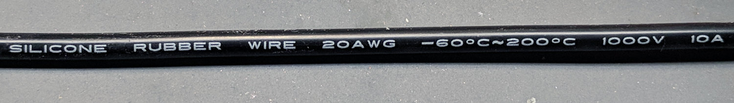
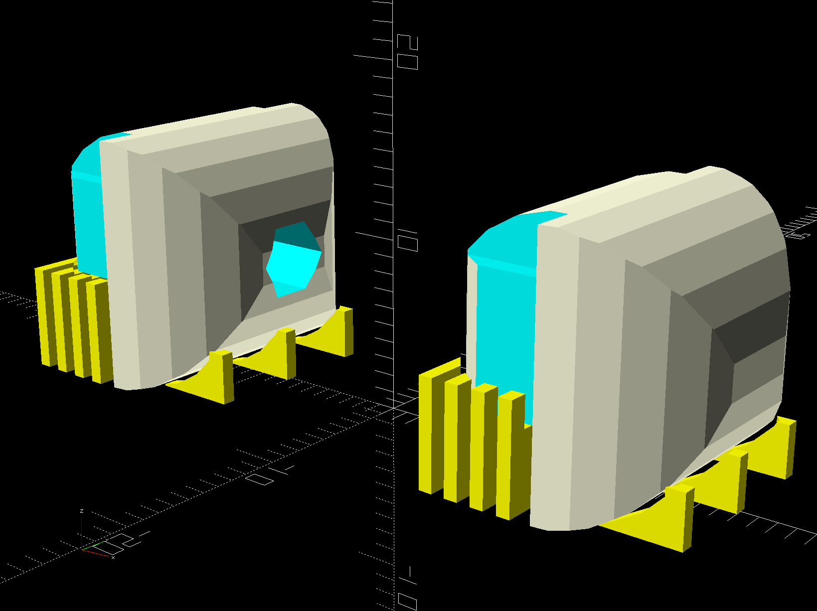
    The central hole in the left cap passes 24 AWG silicone wires from the power supply, with 28 AWG silicone wires snaking down through the L-shaped rectangular cutouts along the extrusion to the LED module’s solder pads.

    The model includes built-in support:

    TL-2010Q COB LED Light Bars - end caps - Build layout
    TL-2010Q COB LED Light Bars – end caps – Build layout

    Assuming the curved ends didn’t need support / anchors holding them down turned out to be completely incorrect:

    Juki TL-2010Q COB LED - curled endcaps
    Juki TL-2010Q COB LED – curled endcaps

    Fortunately, those delicate potato chips lived to tell the tale and, after a few design iterations, everything came out right:

    Juki TL-2010Q COB LED - heatsink endcap - internal connections
    Juki TL-2010Q COB LED – heatsink endcap – internal connections

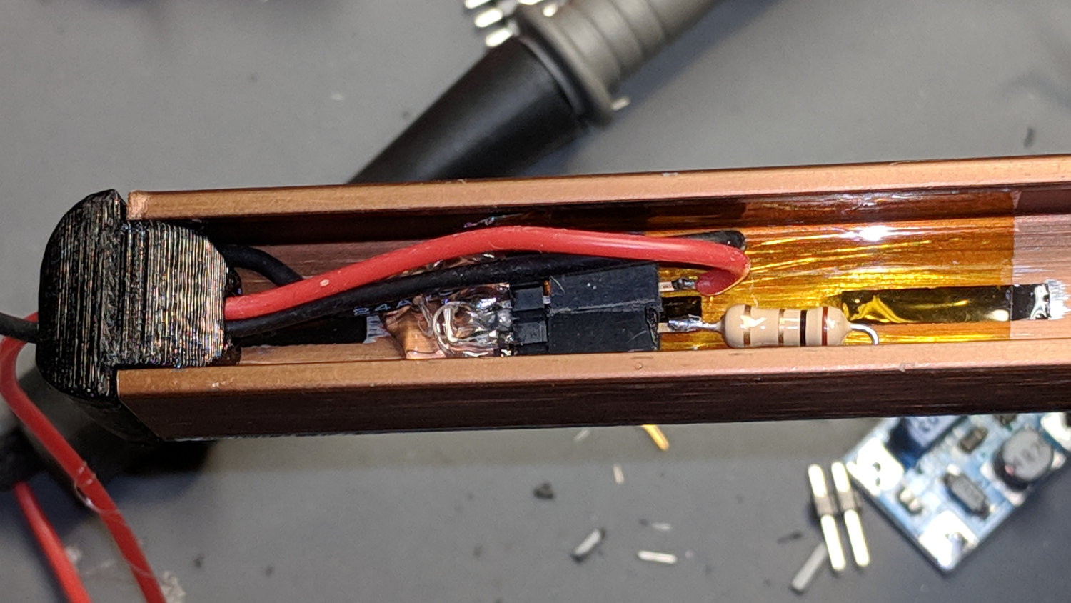
    The “connector”, such as it is, serves to make the light bar testable / removable and the ballast resistor tweakable, without going nuts over the details. The left side is an ordinary pin header strip held in place with hot melt glue atop the obligatory Kapton tape, because the heatsink doesn’t get hot enough to bother the glue. The right side is a pair of two-pin header sockets, also intended for PCB use. The incoming power connects to one set and the ballast resistor to the other, thusly:

    Juki TL-2010Q COB LED - light bar connector diagram
    Juki TL-2010Q COB LED – light bar connector diagram

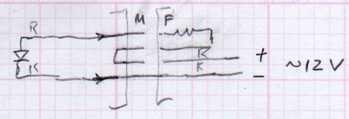
    The diagram is flipped top-to-bottom from the picture, but you get the idea. Quick, easy, durable, and butt-ugly, I’d say.

    The next step was to mount it on the sewing machine and steal some power, but that’s a story for another day.

    The relevant dimensions for the aluminum extrusion:

    Aluminum shelf bracket extrusion - dimensions
    Aluminum shelf bracket extrusion – dimensions

    The OpenSCAD source code as a GitHub Gist:

    // Juki TL-2010Q Sewing Machine – COB LED Light Bars
    // Ed Nisley – KE4ZNU
    // 2019-01
    /* [Layout Options] */
    Layout = "Build"; // [Bracket,Endcap,Show,Build]
    Wiring = [1,0]; // left and right wire holes
    BuildSupport = true;
    /* [Extrusion Parameters] */
    ThreadWidth = 0.40;
    ThreadThick = 0.20;
    HoleWindage = 0.2;
    Protrusion = 0.1;
    //—–
    // Shelf bracket used as LED heatsink
    /* [Hidden] */
    LEDPlate = [15.0,2.4]; // 2D coords from end of LED
    BktOuter = [15.9,12.6 + LEDPlate.y]; // 2D coords as seen from end of extrusion
    BktWalls = [1.3,2.2 + LEDPlate.y]; // … extend base to cover LED
    BktCap = [2.5,3.0];
    BracketPoints = [
    [0,0],
    [BktOuter.x,0],
    [BktOuter.x,BktOuter.y],
    [(BktOuter.x – BktCap.x),BktOuter.y],
    [(BktOuter.x – BktCap.x),(BktOuter.y – BktCap.y)],
    [(BktOuter.x – BktWalls.x),(BktOuter.y – BktCap.y)],
    [(BktOuter.x – BktWalls.x),BktWalls.y],
    [BktWalls.x,BktWalls.y],
    [BktWalls.x,(BktOuter.y – BktCap.y)],
    [BktCap.x,(BktOuter.y – BktCap.y)],
    [BktCap.x,BktOuter.y],
    [0,BktOuter.y],
    [0,0]
    ];
    BracketPlugInsert = 10.0; // distance into bracket end
    WireOD = 1.6; // COB LED jumpers – 24 AWG silicone
    WireOC = BktOuter.x – 2*BktWalls.x – WireOD;
    echo(str("Wire OC: ",WireOC));
    CableOD = 4.0; // power entry cable
    CapSides = 2*3*4;
    //—–
    // Useful routines
    module PolyCyl(Dia,Height,ForceSides=0) { // based on nophead's polyholes
    Sides = (ForceSides != 0) ? ForceSides : (ceil(Dia) + 2);
    FixDia = Dia / cos(180/Sides);
    cylinder(r=(FixDia + HoleWindage)/2,
    h=Height,
    $fn=Sides);
    }
    //—–
    // Endcap with smooth rounding
    // Wires = true to punch holes for LED wires
    module Endcap(Wires = true) {
    // arc length to flatten inside of cap
    // not needed to build in normal orientation
    m = BktOuter.x/2 – sqrt(pow(BktOuter.x/2,2) – pow(BktOuter.x – 2*BktCap.x,2)/4);
    difference() {
    translate([0,0,BktOuter.y/2]) // basic endcap shape
    intersection() {
    cylinder(d=BktOuter.x,h=BktOuter.y,$fn=CapSides,center=true);
    rotate([90,0,0])
    rotate(180/CapSides)
    cylinder(d=BktOuter.y,h=BktOuter.x,$fn=CapSides,center=true);
    }
    translate([-BracketPlugInsert,0,0]) // extrusion + LED plate
    Bracket(BracketPlugInsert);
    if (false) // flatten inner end
    translate([-BktOuter.y + m,0,BktOuter.y/2])
    cube([BktOuter.y,BktOuter.x,BktOuter.y],center=true);
    if (Wires) {
    for (j=[-1,1]) // COB LED connections
    translate([WireOD – BktOuter.x/2,j*WireOC/2,(BktWalls.y + WireOD – Protrusion)/2])
    rotate([0,00,0])
    cube([BktOuter.x,WireOD + Protrusion,BktWalls.y + WireOD + Protrusion],center=true);
    translate([0,0,BktOuter.y/2]) // power entry / exit
    rotate([0,90,0])
    translate([0,0,-BktOuter.x])
    rotate(180/6)
    PolyCyl(CableOD,2*BktOuter.x,6);
    }
    }
    }
    // Totally ad-hoc support structures
    module Support(Wiring = false) {
    Spacing = 4*ThreadWidth;
    NumBars = floor((BktOuter.y/2) / Spacing);
    echo(str("Support bars: ",NumBars));
    color("Yellow") {
    render() difference() {
    union() {
    for (i=[1:NumBars]) // inside extrusion
    translate([-i*Spacing,0,(BktWalls.y + WireOD)/2])
    cube([2*ThreadWidth,BktOuter.x – 0*BktWalls.x,BktWalls.y + WireOD],center=true);
    if (true)
    for (j=[-1:1]) // reduce outside curve uplift
    translate([0.3*BktOuter.y,j*BktOuter.x/3,BktOuter.y/10])
    cube([BktOuter.y/3,2*ThreadWidth,BktOuter.y/5],center=true);
    }
    minkowski() { // all-around clearance
    Endcap(Wiring);
    cube(2.0*ThreadThick,center=true);
    }
    if (Wiring) {
    translate([0,0,BktOuter.y/2]) // remove rubble from wire bore
    rotate([0,90,0])
    translate([0,0,-BktOuter.x])
    rotate(180/6)
    PolyCyl(CableOD,2*BktOuter.x,6);
    }
    }
    if (false)
    translate([-(BktOuter.x/4 + ThreadWidth),0,ThreadThick/2]) // adhesion pad
    cube([BktOuter.x/2,BktOuter.x – BktWalls.x,ThreadThick],center=true);
    // translate([BktOuter.x/3,0,ThreadThick/2]) // adhesion pad
    // cube([0.3*BktOuter.x,0.7*BktOuter.x,ThreadThick],center=true);
    if (false)
    for (j = [-1:1]) // tie pad to bottom of cap
    translate([-(4*ThreadWidth)/2,j*(BktOuter.x – 2*ThreadWidth)/2,ThreadThick/2])
    cube([4*ThreadWidth,2*ThreadWidth,ThreadThick],center=true);
    }
    }
    //—–
    // Heatsink extrusion + LED plate
    // Centered on Y with Length extending in +X
    module Bracket(Length = 10)
    translate([0,-BktOuter.x/2,0])
    rotate([90,0,90])
    linear_extrude(height = Length,convexity=3)
    polygon(points=BracketPoints);
    //—–
    // Build things
    if (Layout == "Bracket")
    Bracket();
    if (Layout == "Endcap")
    Endcap();
    if (Layout == "Show") {
    translate([BktOuter.x,0,0])
    Endcap(Wiring[1]);
    translate([-BktOuter.x,0,0])
    rotate(180)
    Endcap(Wiring[0]);
    color("Yellow",0.35)
    translate([-BktOuter.x/2,0,0])
    Bracket(BktOuter.x);
    }
    if (Layout == "Build") {
    translate([BktOuter.y,0,0]) {
    Endcap(Wiring[0]);
    if (BuildSupport)
    Support(Wiring[0]);
    }
    translate([-BktOuter.y,0,0]) {
    Endcap(Wiring[1]);
    if (BuildSupport)
    Support(Wiring[1]);
    }
    }

  • DSO150: USB Battery Charger

    Continuing the process of silk-purse-izing the DSO150, a batch of USB 1S lithium battery charger modules arrived from halfway around the planet. I drilled & filed a suitable hole / slot / aperture in one of the few remaining spots in the case, then stuck the PCB to the bottom with good foam tape:

    DSO150 - USB charger - internal layout
    DSO150 – USB charger – internal layout

    Because the charger includes cell protection circuitry, I replaced the original protected 18650 cell with a bare cell sporting solder tabs. The cell should go directly to the charger board, but the switch disconnects the + wire; I’m unwilling to believe the charger won’t slowly and inexorably discharge the cell if I don’t use the DSO150 for a few months. It could happen.

    A label makes the hole look almost professional:

    DSO150 - USB charger - Micro-B jack
    DSO150 – USB charger – Micro-B jack

    Well, makes it look Good Enough™, I suppose.

    The power switch gets a label, too:

    DSO150 - USB charger - battery switch
    DSO150 – USB charger – battery switch

    Flipping the switch ON lights up the scope from the battery.

    The charger (sensibly) will not route power from the USB port to the scope without a battery, so you must plug in a USB source with the switch ON, then flip the switch OFF. I don’t know why you’d want to do that, but there you go.

    Now it’s a real portable instrument, with all the inconvenience of managing a built-in lithium cell.

  • Vacuum Tube LEDs: Radome Prototype

    Definitely not a vacuum tube:

    Arduino Pro Mini - NP-BX1 cell - SK6812 - blue phase
    Arduino Pro Mini – NP-BX1 cell – SK6812 – blue phase

    It’s running the same firmware, though, with the Arduino Pro Mini and the LEDs drawing power from the (mostly) defunct lithium battery.

    The LED holder is identical to the Pirhana holder, with a 10 mm diameter recess punched into it for the SK6812 PCB:

    Astable Multivibrator Battery Holder - Neopixel PCB - Slic3r
    Astable Multivibrator Battery Holder – Neopixel PCB – Slic3r

    Those embossed legends sit in debossed rectangles for improved legibility. If I repeat it often enough, I’m sure I’ll remember which is which.

    The 3.6 V (and declining) power supply may not produce as much light from the SK6812 LEDs, but it’s entirely adequate for anything other than a well-lit room. The 28 AWG silicone wires require a bit of careful dressing to emerge from the holes in the radome holder:

    SK6812 LED PCB - Pirhana holder wiring
    SK6812 LED PCB – Pirhana holder wiring

    The firmware cycles through all the usual colors:

    Arduino Pro Mini - NP-BX1 cell - SK6812 - orange phase
    Arduino Pro Mini – NP-BX1 cell – SK6812 – orange phase

    A pair of tensilized 22 AWG copper wires support the Pro Mini between the rear struts. The whole affair looks a bit heavier than I expected, though, so I should reduce the spider to a single pair of legs with a third hole in the bottom of the LED recess for the data wire.

    The OpenSCAD source code needs some refactoring and tweaking, but the Pirhana LED solid model version of the battery holder should give you the general idea.

  • Vacuum Tube LEDs: Arduino Pro Mini vs. NP-BX1 Battery

    A year or so ago, a certain Young Engineer suggested my Vacuum Tube Lights really needed battery power and rebuffed my feeble objections concerning low LED intensity (3.6-ish V, not plug-in 5 V USB) and short run time (because three constantly lit LEDs draw too much current). Having a spare NP-BX1 holder lying about, here’s a feasibility study:

    Arduino Pro Mini - Neopixel - NP-BX1 battery
    Arduino Pro Mini – Neopixel – NP-BX1 battery

    Not much to it, eh?

    Hitching the DSO150 to a Tek current probe (which needs a 50 Ω load, thus the terminator on the BNC tee) seems a clear-cut case of a sow’s ear joining forces with a silk purse:

    DSO150 - Arduino Pro Mini - Neopixel current
    DSO150 – Arduino Pro Mini – Neopixel current

    It was just sitting there, so why not?

    Seen with a bit more detail on a better scope:

    Ard Mini - NP-BX1 - SK6812 - 10 mA-div
    Ard Mini – NP-BX1 – SK6812 – 10 mA-div

    Each vertical increment represents the current into a single LED (at 10 mA/div), with the PWM cycles ticking along at 1.3 kHz.

    The current steps aren’t the same height, because the LEDs have different forward voltages. The taller step (at the top) probably comes from the red LED, with the other two being blue and green. The maximum current is only 40 mA, not the 60 mA you’d expect with a 5 V supply.

    The PWM width, of course, determines the brightness of each LED. Eyeballometrically, the average current will be half of 40 mA for (just less than) half of each PWM cycle, so figuring each SK6812 module (there’s only one here) will draw 10 mA seems reasonable.

    The “base load” from the Arduino looks like 2 mA, so there’s not much point in removing its power and status LEDs.

    The NP-BX1 lithium cell has lost enough capacity to no longer power my Sony HDR-AS30V helmet camera for at least half of a typical ride. The camera draws around 1 A, so you can clearly see the defunct batteries:

    Sony NP-BX1 - 2018-04-24
    Sony NP-BX1 – 2018-04-24

    If the average voltage during discharge is 3.3. V, then a 10 mA load would be 33 mW and a defunct NP-BX1 battery with 2 W·h capacity (at 1 A) might provide 60 hours of continuous use. I’d expect more capacity at lower current, although it’s not clear the cells actually behave that way.

    So a battery-powered Vacuum Tube Light might make sense, perhaps as romantic illumination for techie snuggling:

    21HB5A - Guilloche platter
    21HB5A – Guilloche platter

    Ya never know …

  • DMM Probes

    After the Great DMM Probe Debacle, I picked up similar-but-different set of cheap probes and clip leads.

    The needle-tip probes carry a 20 A current rating:

    No-Name DMM probes - needle tip - 20 A
    No-Name DMM probes – needle tip – 20 A

    If you look out along the wire, though, you’ll find a 10 A rating:

    No-Name DMM probes - needle tip - 10 A wires
    No-Name DMM probes – needle tip – 10 A wires

    Now, even though 20 AWG wire in silicone may carry a 17 A spec, the corresponding 200 °C temperature seems excessive for a test probe. Limiting the current to 10 A would reduce the power dissipation by two thirds, which should limit the temperature rise. Whether the wire actually contains 20 AWG of actual copper strands remains an open question.

    The kit also had banana plug / test hooks with no particular rating, although the wire allegedly has 16 AWG conductors:

    DMM Clip Leads - 16 AWG
    DMM Clip Leads – 16 AWG

    The banana plug / alligator clip combo claims 30 A, also with 16 AWG conductors. Who knows? It could be true.

    For comparison, the Siglent SDM3045 DMM came with these probes:

    Siglent DMM probes - 10 A
    Siglent DMM probes – 10 A

    The probes carry a 10 A rating and, although the wires aren’t branded, I’ll assume they have good-enough QC to ensure the copper matches the claims. The production values seem a bit higher, too, even if they bear a striking resemblance to the cheap probes.

    And, for reference, the probes with the cold solder joint also claim 20 A:

    No-Name DMM probes - 20 A
    No-Name DMM probes – 20 A

    Wouldn’t trust any of ’em for more than a few amps, tops …

  • So(l)der Wick Variations

    In the process of sorting out the Small Box o’ Soldering Tools, this well-used treasure emerged:

    Soder-Wick - Original - Size 2
    Soder-Wick – Original – Size 2

    Yeah, the Genuine Article. Note the spelling and hyphenation: “Soder-Wick” is a both Registered Trademark® and patented.

    Of course, the patent having long expired, there exist knockoffs with slightly different spelling:

    Solder Wick - Knockoff - Size 2mm
    Solder Wick – Knockoff – Size 2mm

    And labeling:

    Solder Wick - Knockoff - Size Good
    Solder Wick – Knockoff – Size Good

    “Size Good”. I like that. “Made in Taiwan”, though, suggests it’s been in my collection for quite a while.

    Despite the fact they’re all supposed to be coated with flux, I generally run a flux pen over whatever length I’m using, because it’s the only way to be sure.

  • Astable Multivibrator: DSO150 vs. Capacitor Voltage

    With the astable blinking green, I had to do this:

    DSO150 - 2N7000 astable cap voltage
    DSO150 – 2N7000 astable cap voltage

    It blinks every two seconds because it uses 1 MΩ timing resistors, rather than the 2 MΩ resistors in the first version.

    Because the DSO150 runs from the internal battery, you can clip it anywhere with few ill effects. The blinky runs from a battery, too, but connecting a high-impedance node to what’s basically the power line common may lead to heartache and confusion; it’s generally a Bad Habit.

    A closer look at the DSO150 screen shows the expected bipolar exponential waveform across the 1 µF timing cap:

    DSO150 - 2N7000 astable cap voltage - screen detail
    DSO150 – 2N7000 astable cap voltage – screen detail

    The scope triggering seems iffy, as the trace capture pauses every now and again for no apparent reason. This may have something to do with the very slow sweep speed; at 500 ms/div, the complete waveform takes forever to accumulate.

    At least we know the signal lies well within the DSO150’s bandwidth!