Ed Nisley's Blog: Shop notes, electronics, firmware, machinery, 3D printing, laser cuttery, and curiosities. Contents: 100% human thinking, 0% AI slop.
I walked up to a sign-in kiosk with an interesting difference:
Kiosk app update
If they ask a question on a public-facing device, they must expect a response. Right?
This interesting assembly sprouted from an upstairs wall:
Wash hose valve
The brass fitting seems intended for a braided hose leading to a nozzle, but there was no corresponding floor drain in the room. I’m sure the shutoff valve in the bottom elbow was turned off.
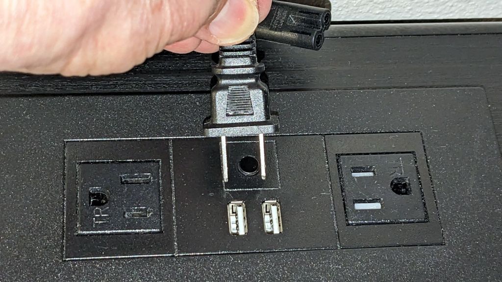
Back in the motel, I attempted to plug in my charger:
USB sockets vs AC plug
The currently trendy black-on-black design scheme doesn’t work well in the low-light environment of a motel room. The white plastic tabs in those USB sockets were the only visible parts of that whole assembly.
As the saying goes, “Without temptation, there can be no virtue.”
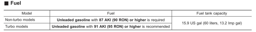
According to the manual, which I have hitherto had no reason to doubt, our non-turbo 2015 Subaru Forester has a 15.9 gallon fuel tank:
Subaru Forester – Fuel Capacity Chart
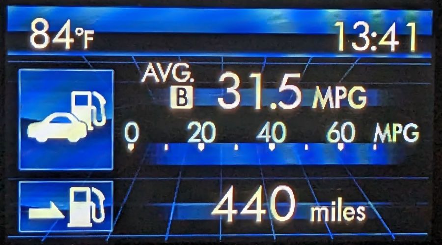
One screen shown on the dashboard’s Multi-Function Display gives the current mileage and estimated range:
Forester – MPG Range
Dividing those two numbers gives you 13.97 gallons, the current fuel level. As you’d expect, should the average miles per gallon change, the range will change accordingly.
The trip odometer says we have driven 72.8 miles since I filled the tank. Dividing that by the average mpg gives 2.3 gallons, so the tank could possibly hold 16.2 gallons, which, given all the averages involved, is reasonably close to the 15.9 gallons shown in the manual.
Being that type of guy, I have a spreadsheet tallying each fillup since the car was new:
8.1 gal average
7.5 gal median
13.9 gal maximum
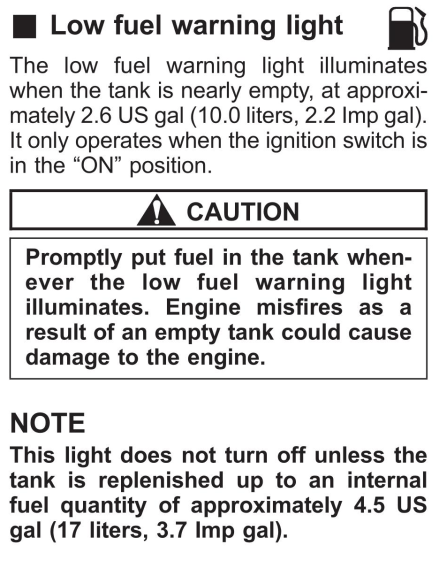
Long ago, my father taught me to fill the tank when the needle got halfway down and I’ve been doing so ever since. As a result, we have only rarely seen the Low Fuel Warning Light:
Subaru Forester – Low Fuel Warning Light info
A concatenation of unavoidable events put us southbound on I-87 when that light went on. Given the estimated range of 70-ish miles, I planned to refuel at the New Baltimore Service Area, about a dozen miles ahead.
The engine shut down and all the dashboard warning lights lit up with the Service Area Ahead sign in view:
Out of Gas – Service Area Ahead
All the “facilities” are blank because they’re rebuilding the whole place, with the gas station remaining open.
So I slapped the shifter into neutral and we drifted slowly along the shoulder, under the bridge visible ahead, and eventually came to a halt at the beginning of the exit lane.
There was only one thing to do:
Out of Gas – Walking On
Some storytelling later:
Out of Gas – Walking Back
Just because I could:
Refueling – GPS Track
For what are, I trust, understandable reasons, I started the tracker after I began hiking and forgot to turn it off before driving away.
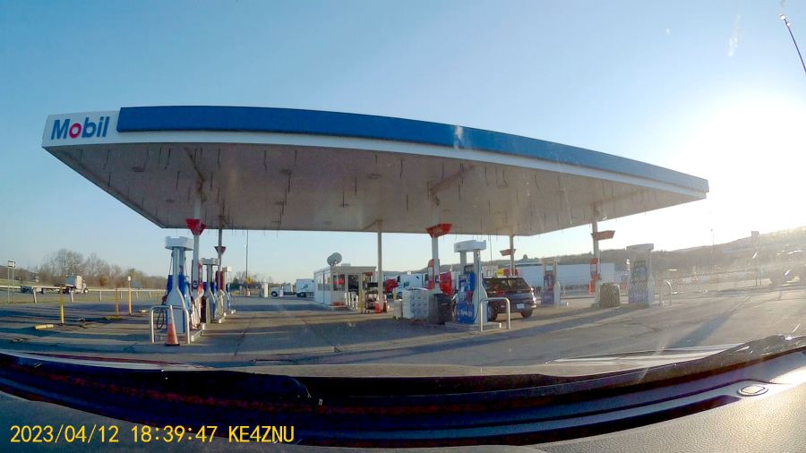
After figuring out the devilishly complex spring-loaded anti-spill spout on the gas can, we drove 1500 feet to the Service Area:
Out of Gas – Service Station
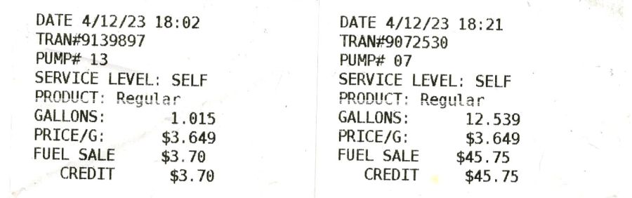
As usual, I filled the tank until the nozzle automatically shut off, for a total of 13.554 gallons in two transactions:
Pump Receipts
Now, it is possible the Forester fuel system has another 2.3 gallons tucked away somewhere, but if that reserve doesn’t make the wheels go around, it’s not doing me the least bit of good.
The fact that I’ve occasionally added just short of 14 gallons suggests the estimated remaining capacity depends strongly on the average mileage up to that point and I have come very very close to running out of gas on several occasions.
As far as I can tell, the usable fuel capacity is a scant 14 gallons and the Low Fuel Light goes on with, at most, a dozen more miles in the tank.
This is the second time in more than half a century of driving I’ve run out of gas.
My father was right and I shall henceforth mend my wayward behavior.
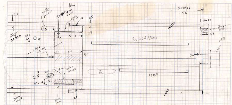
Having acquired some thick-wall (1 inch OD, ¾ inch ID) aluminum tube, making the LED heatsink and lens holder for a running light generates a lotless scrap. A new doodle gives the dimensions in a rather Picasso-ish layout:
Running Light – dimension doodles
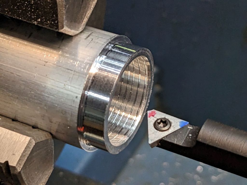
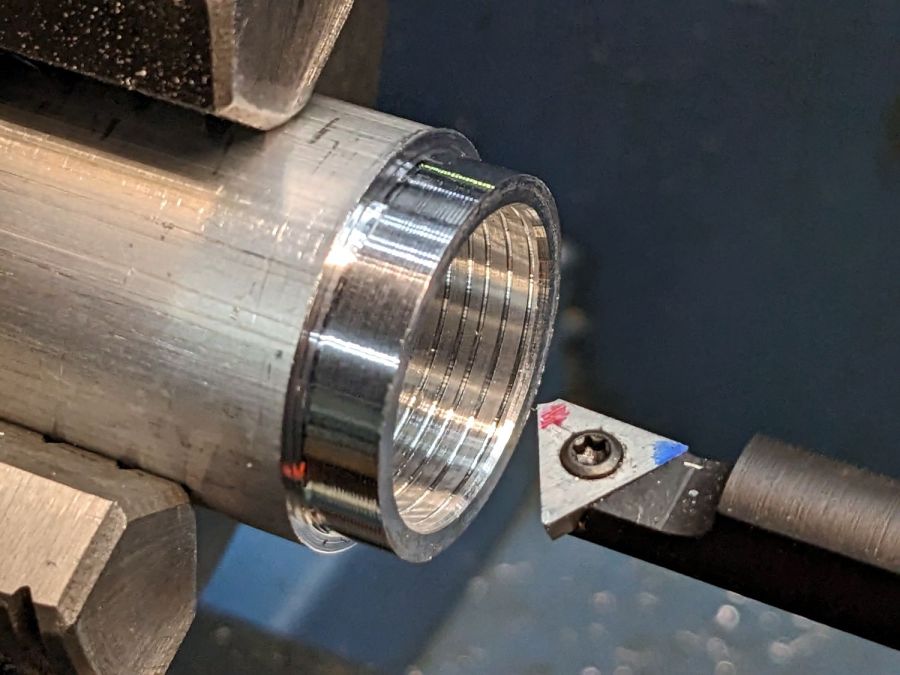
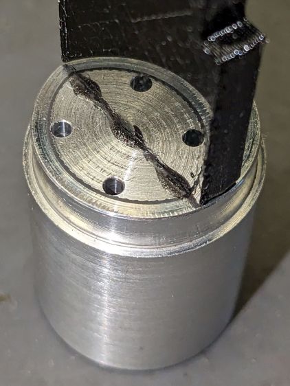
The back end of the tube gets turned down to 23 mm OD and cleaned up to 19 mm ID, then scored to give the epoxy something to grip:
Front Running Light – Heatsink shell scoring
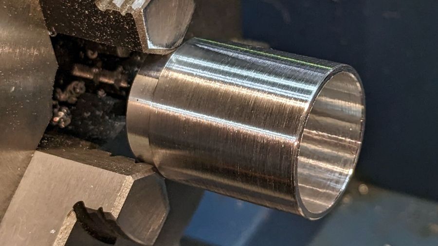
The front end gets bored to 22.5 mm for the lens holder and has its OD cleaned up to 25 mm:
Front Running Light – finished shell
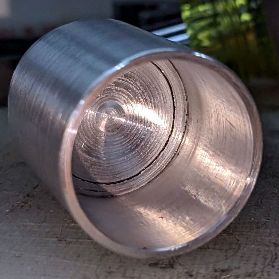
Clean up the end of a ¾ inch rod to 19 mm OD, knurl it a little to increase the OD ever so slightly and improve its griptivity, slice off a bit more than 10 mm, butter it up with JB Weld epoxy, and shove it into the shell with its front end aligned and its back end sticking out:
Front Running Light – epoxied plug in shell – rear
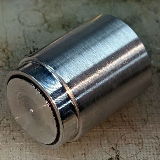
Face off the back end and the front end looks fine as assembled:
Front Running Light – epoxied plug in shell – front
Grab it in the Sherline mill’s three jaw chuck to:
Drill & tap the M3 central hole for the stud holding the circuit plate to the back end
Drill 1.6 mm blind holes for the circuit plate pins
Drill 2 mm through holes for the LED wires, 60° apart
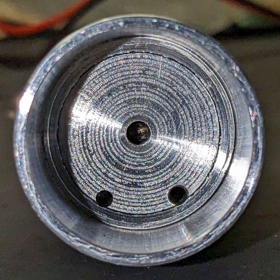
Which looks like this from the front:
Front Running Light – drilled heatsink – front
And like this with the circuit plate screwed & glued to the rear:
Front Running Light – circuit plate mounted
Clean up the OD of some ¾ inch PVC pipe to 25 mm, bore it out to 23 mm.
While the Sherline is set up, drill a pair of 2 mm holes in the lens holder for the wires, aligned so they’ll match the heatsink holes.
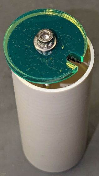
Because we live in the future, laser-cut the rear cap from some edge-lit acrylic with a black inner disk:
Front Running Light – PVC tube – end cap
Cutting that cap with the notch included is now trivially easy, compared to the previous machining.
The color is apparently a side effect of the CO₂ laser vaporizing the plastic, because it emerged during the engraving process.
Polycarb tends to get all melty when cut, so it’s not particularly good for laser machining. Indeed, the engraving produced filaments of (presumably) melted / condensed plastic that I brushed off after taking this picture:
Polycarbonate engrave – 400mm-s 20pct 0.1mm – as cut
If you could put up with the filaments and the poor cut edges, it might be useful for front panel legends and suchlike.
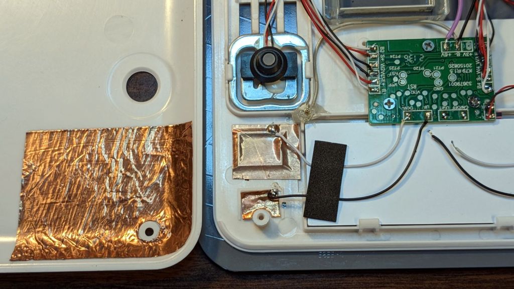
While I was thinking about something else, I added a back shield to our kitchen scale:
SmartHeart 19-106 Scale – button shield
A pogo pin connected to the circuit common contacts the copper foil when the bottom cover is screwed down:
SmartHeart 19-106 Scale – shield pogo pin – detal
The shield prevents the buttons from responding to fingers on the bottom of the scale, so it no longer wakes up when I extract it from the under-cabinet shelf, and concentrates its attention on the buttons, so it no longer seems quite so willing to lock up due to mysterious influences.
With an absurd amount of rebuilding, this scale is becoming not a complete waste of free money.
The batteries soaked up 240 mA·hr of charge, which means the scale drew about 10 mA/day over the last three weeks. Given that the scale’s original 2032 lithium cells have a total capacity around 220 ma·hr for currents in the microamp range, expecting them to supply a current around 10 mA is was absurd.
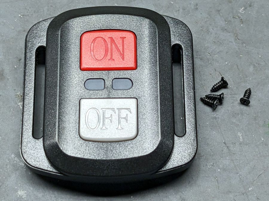
The remote control included with the SJCAM M50 trail camera did absolutely nothing. Not only did it not turn on the camera’s WiFi, the two indicator LEDs between the buttons didn’t blink:
SJCAM M50 remote – front view
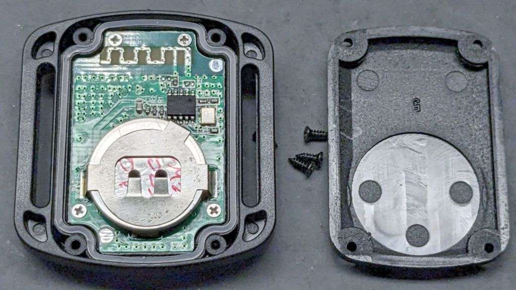
With not much to lose, I removed those four screws and popped the back cover:
SJCAM M50 remote – interior
Yup, the OEM no-name CR2032 lithium cell was dead flat discharged. A new one perked it right up, with blinky LEDs and all.
Now I can check the camera for interesting pix without hauling it into the house:
Note that it’s possible to see the inlet, but not do much with it. I think the bottom plate could be pried off those squishy rubber pillars supporting / isolating the pump, but I didn’t see any need to do so.
The doodle I made at the time gives the dimensions:
OMTech 60 W Laser Air Assist – pump inlet fitting measurements
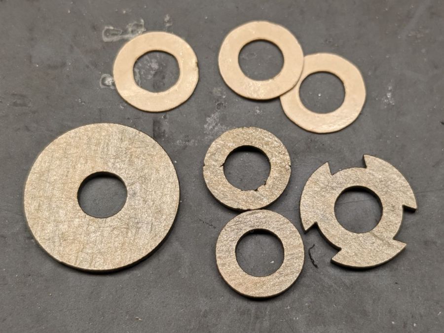
Back then, I thought of 3D printing the fitting, but the fact that the parts had to be 1.5 mm thick suggested laser cutting the parts from acrylic sheet:
Laser cutter air pump – keyed fitting A – parts
The three top disks come from a 3M LSE adhesive sheet and hold the three layers together, with one spare because I know better than to cut exactly as many as I think I’ll need:
Laser cutter air pump – keyed fitting – assembled
The alert reader will note the middle layer in that picture isn’t a simple round disk. After putting the first version together, I realized the keyed bottom layer could continue turning until it fell out, so I added stops to the middle disk:
Laser cutter air pump – keyed fitting B – parts
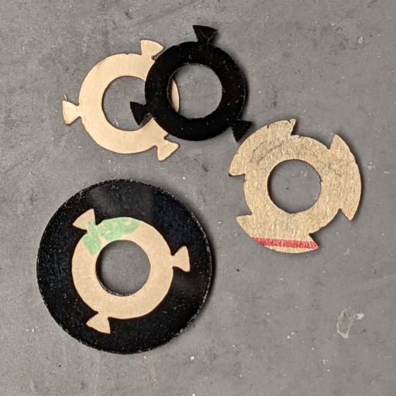
Those stops came from the bottom layer layout by welding together three copies of the key opening:
Laser Cutter Air Assist Pump Fitting – LB design layout
Space three of those shapes around the ring, subtract them from the outer disk (the same size as the keyed layer), weld them to the middle disk (the same size as the previous middle), and the stops appear as if by magic. Gotta love this geometry stuff.
The same design produced matching adhesive disks that I applied with tweezers, but if you were doing it in production you’d definitely want to apply a sheet of adhesive to a sheet of acrylic and cut them in the same operation.
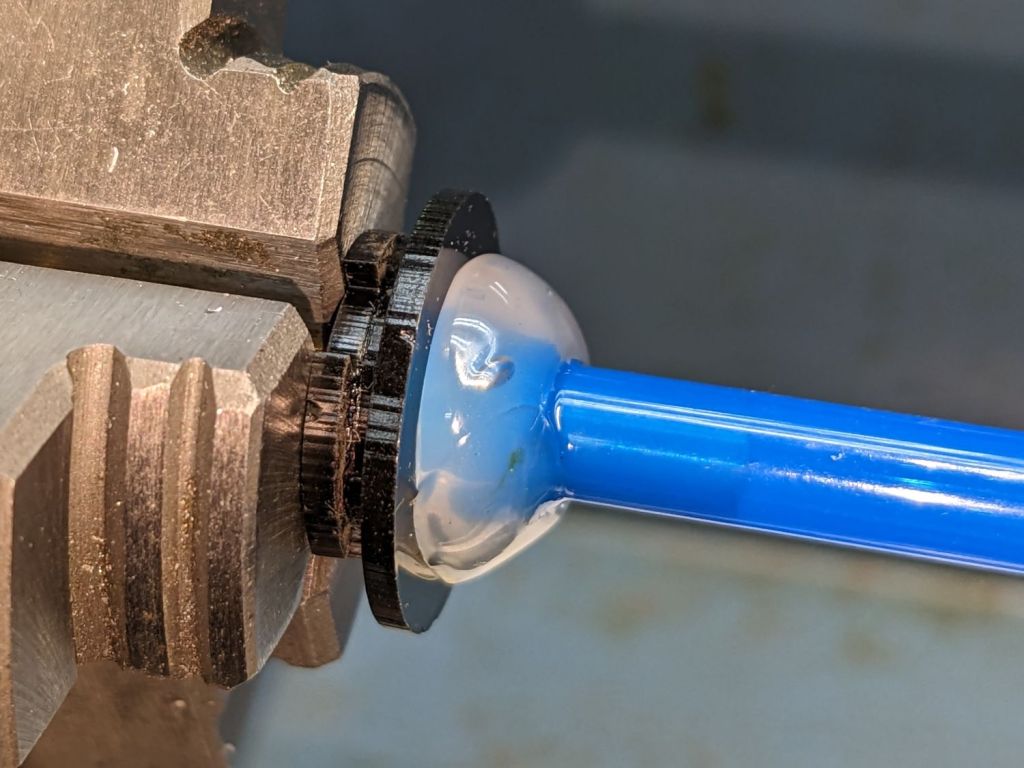
Soften the slightly curved PVC tubing with a heat gun, persuade it to become straight, jam a drill bit inside and grab it in the lathe chuck to keep the fitting perpendicular, glob hot-melt glue around the tubing to hold it in place, and let it cool:
Laser cutter air pump – fitting hose glue
Hot melt glue doesn’t adhere well to acrylic, so cut & apply a disk of LSE adhesive between them, because it sticks like … glue … to both substances.
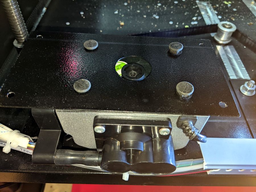
Mark and step-drill a hole in the bottom of the laser cabinet, install the fitting on the pump, line things up, and it’s ready to screw down:
Laser cutter air pump – first trial fitting
Whereupon I discovered the four silicone rubber feet I added to support the pump base plate and keep it from vibrating against the cabinet let the flexy rubber posts supporting the pump extend too far, thus causing the whole pump to rest on the glue around the fitting.
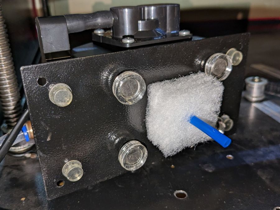
Well, I can fix that and, while I’m at it, a snippet of fibrous stuff will keep the tube from rattling around:
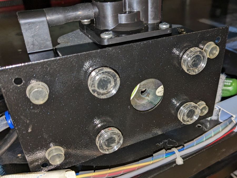
Laser cutter air pump – bottom view – assembled
The four clear disks are 3 mm acrylic stuck to the rubbery feet with more LSE adhesive, with rings around the top to keep everything aligned. It may be possible to line up all four of those things while lowering the pump in place, but not for me.
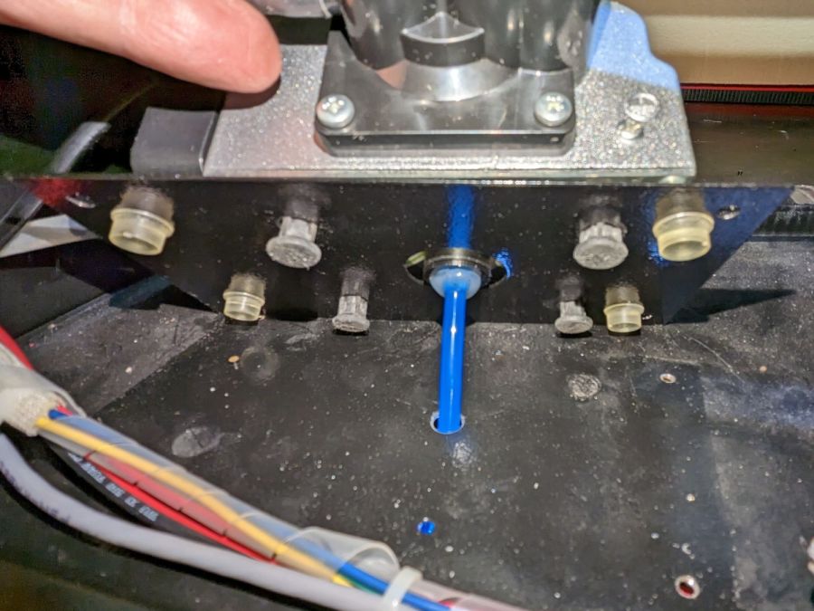
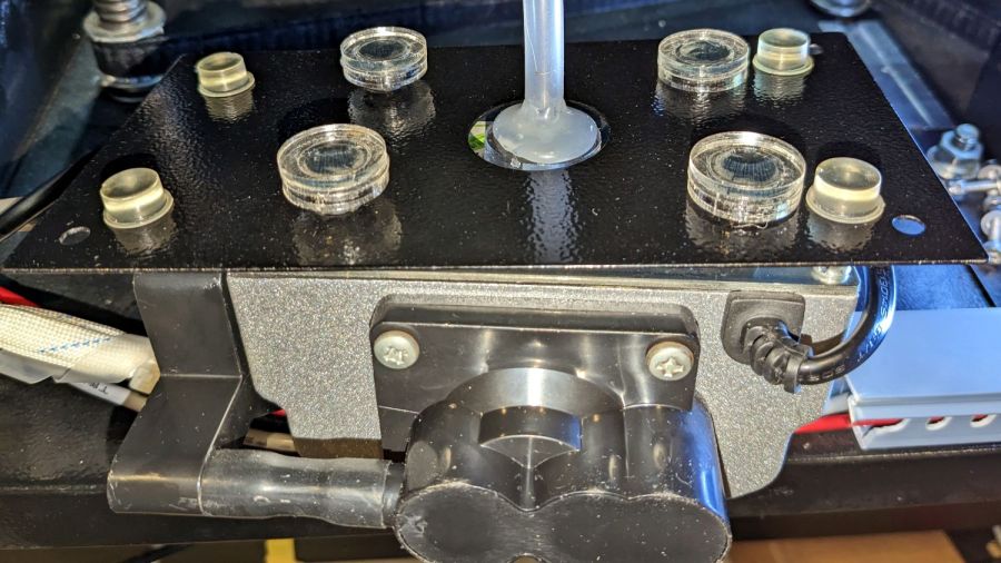
With all that once again ready to screw down, the blue tube and its fuzzy felt bumper fell right off, taking the pump’s air inlet connector along. Much to my surprise, the pump draws air through a simple 6 mm hole in its bottom plate:
Laser cutter air pump – without fitting socket
Now, the reason I went through all these gyrations was because I had examined that connector, decided it was an integral part of the pump, and there was no way for me to get it off without tearing the pump apart or applying brute force.
Apparently, all the twisting & turning I did while getting the fittings assembled worked the connector’s unthreaded stem loose in its hole, ready to come out with the slightest pull.
Verily: Hell hath no fury like that of an unjustified assumption.
So I cut out a simple disk of 4.5 mm acrylic, hot-melt blobbed a 6 mm ID silicone tube into it, stuck it onto the pump with a (punch-cut!) disk of 3M double-sided foam tape, and declared victory:
Laser cutter air pump – simple disk fitting
Fortunately, the step drill I used on the cabinet left a 9.5 mm hole easily passing the silicone tube’s 9 mm OD, so it all fit together just like I knew what I was doing.
The silicone tubing has a much larger ID than the original plastic fitting, but the assist air flow remains around 10 l/min. That’s down from the 14 l/m when I installed the flowmeter and 12 l/min with the dual-path assist air control plumbing, but didn’t change with all this fiddling, so the real restriction is in all the blue tubing and myriad fittings on the way to the nozzle.
On the upside, I now know a bit more about small-scale laser cutting and am well-satisfied with the results.