Ed Nisley's Blog: Shop notes, electronics, firmware, machinery, 3D printing, laser cuttery, and curiosities. Contents: 100% human thinking, 0% AI slop.
Squirting it with circuit cooler brought it back to life, albeit briefly, so it’s a real thermal failure. OK, after I get smacked upside the head twice, I can recognize a problem when I see it.
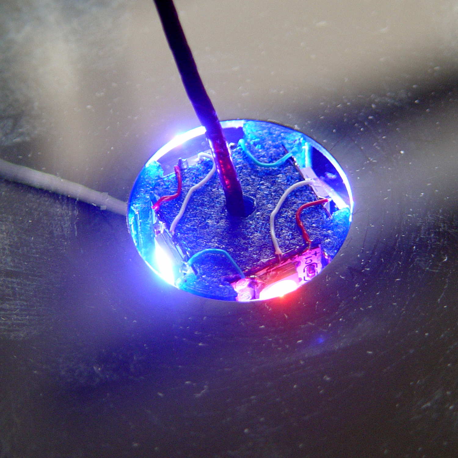
I removed the top cover and jammed a themocouple into the screw hole in the middle of the pillar:
Mood Light – thermocouple location
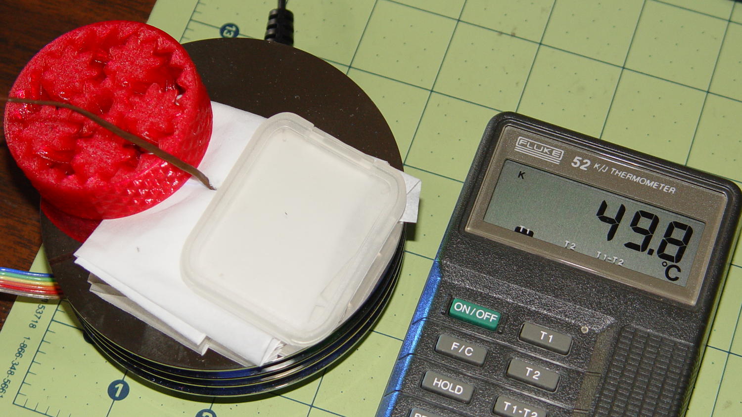
A folded tissue weighted down with random desktop junk kept the breeze out of the interior:
Mood Light – PWM 128 temperature measurement
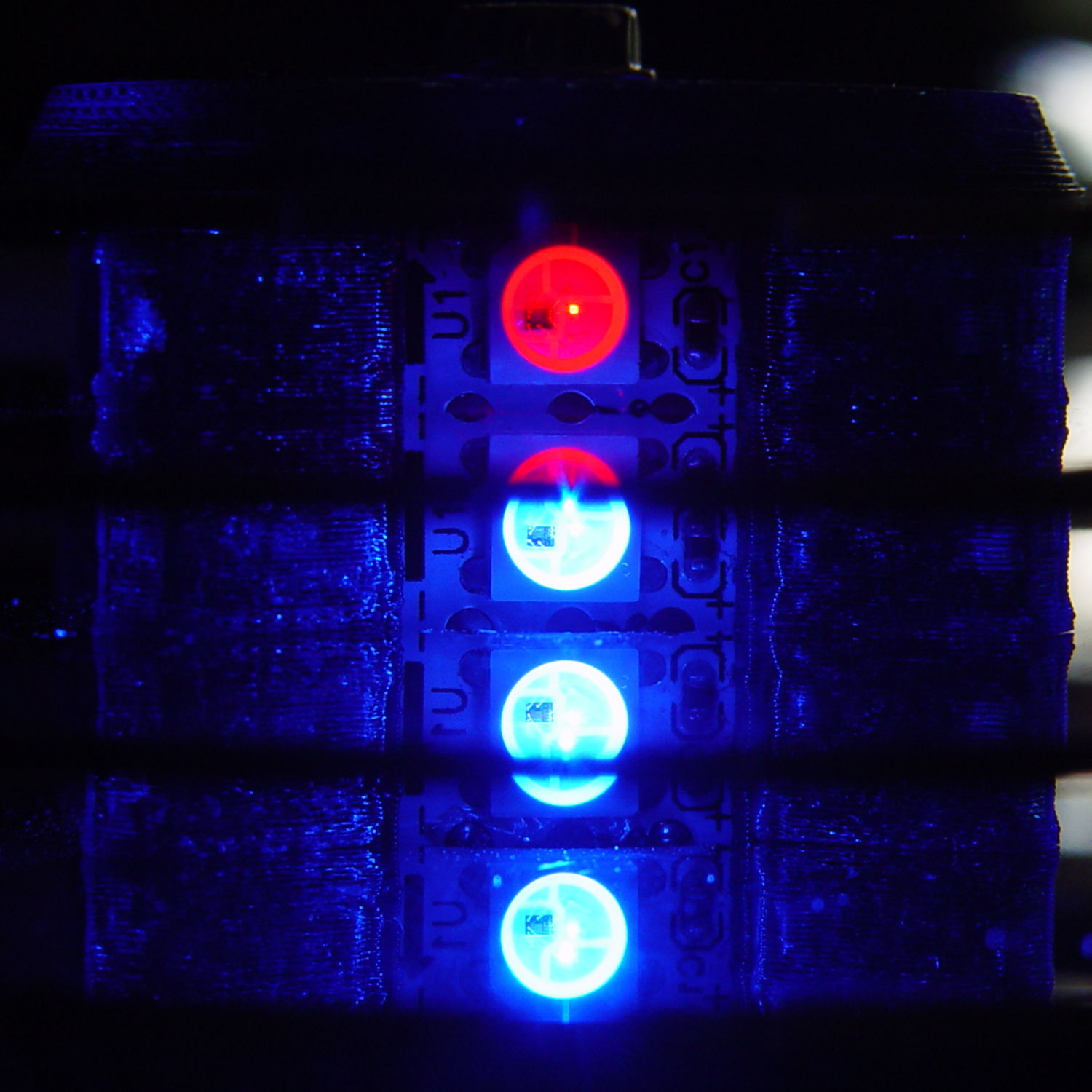
If the middle of the column hits 50 °C, what’s it like inside the 5050 packages with all those LEDs blazing away? Looks like I’ve been cooking those poor knockoff Neopixels to death.
The temperature is 50 °C with the LEDs running at maximum PWM = 128. Reducing the maximum PWM to 64 reduces the core to 30 °C and that dead blue LED springs back to life.
Figuring each LED package dissipate 250-ish mW at full throttle, that’s 120 mW at PWM 128 / 60 mW at PWM 64. The set of 12 packages dissipates 1.4 W / 750 mW, so, in a 22 °C room, the thermal coefficient is up around 10 to 20 °C/W, which is somewhere between bad and awful. Running the LEDs at full throttle obviously isn’t an option and even half-throttle really doesn’t work.
So, OK, mounting LED strips on a clever 3D printed plastic column with zero air circulation isn’t nearly as smart an idea as I thought: barely more than a watt burns right through the redline.
The Neopixel specs have nothing to say about the thermal coefficient from the LED junctions to the package leads, but cooling the copper conductors in the flex PCB can’t possibly hurt.
No, I do not want to CNC machine an aluminum pillar with little tabs on the platter for better heatsinking. It would be an interesting design project, though.
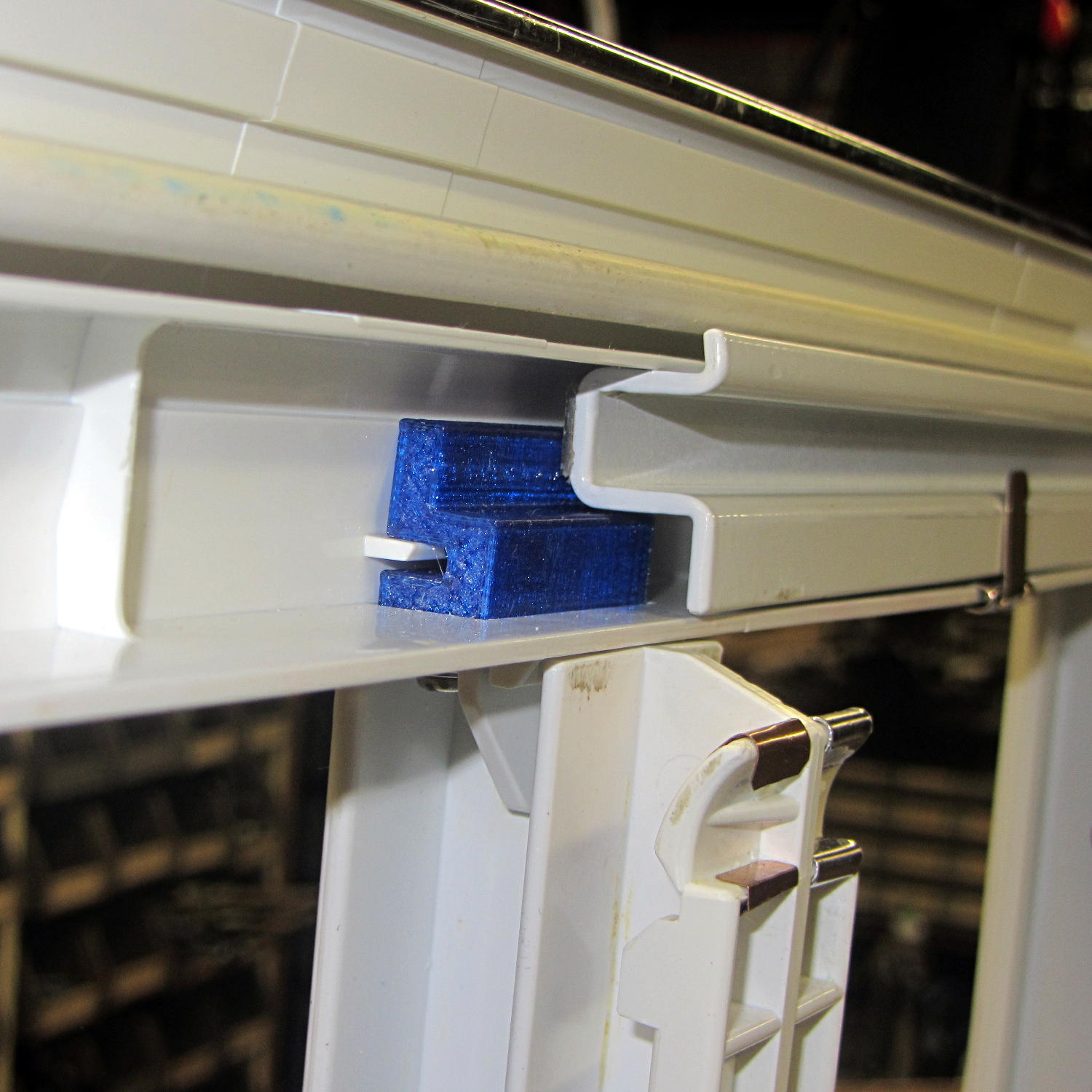
The tab supporting the strut with the center slides for the lower drawers in our Whirlpool refrigerator broke of its own accord. This is a problem of long standing, somewhat exacerbated by the fact that lifting the strut will break the tab without much effort at all, but this time the drawers pulled the strut downward hard enough to not only break the tab, but also tear the small tabs that align the bracket right out of the frame.
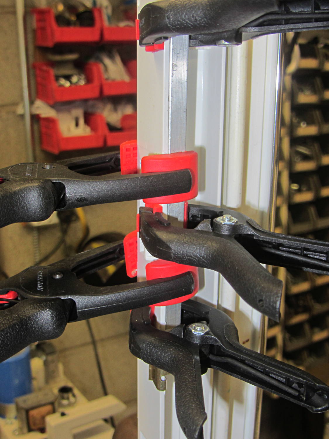
While pondering the problem, I glued the broken chunk back into the frame:
Refrigerator Drawer Strut – clamping front plate
We agreed that, after nigh onto two decades, it would be OK to swap the position of the two drawers, so as to let the strut use the undamaged part of the frame seen below. Presumably, we’ll eventually get used to having the apples on the right and the veggies on the left.
But it was obvious Something Serious Had To Be Done about the tab.
The tab should align like this inside the frame:
Refrigerator Drawer Strut Tab – alignment
The rightmost part of the tab rests atop a U-shaped metal bar that also supports and stiffens the entire front of the frame, but cantilevering the weight of both drawers on that extended tab overpowered my last attempt at making a glue joint. Soooo, I decided to build a (wait for it …) 3D printed part that screws firmly to the front of the strut.
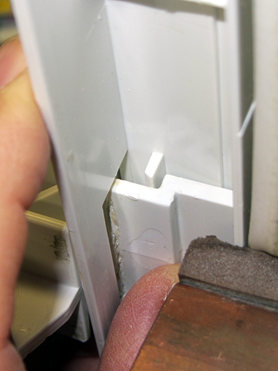
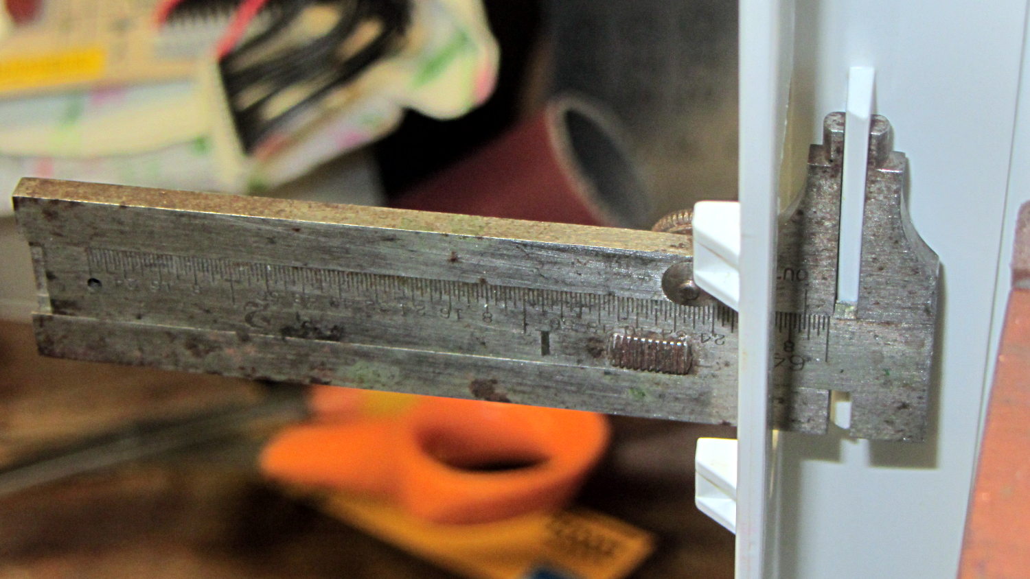
The first step involved introducing the strut to Mr Belt Sander to strip the wreckage of the OEM tab from the front end (visible through the opening) and smooth things out, then measuring the remainder. The locating flange inside the frame almost defeated me, but eventually I found a tool that fit inside the strut opening and around the flange:
Refrigerator Drawer – measuring flange
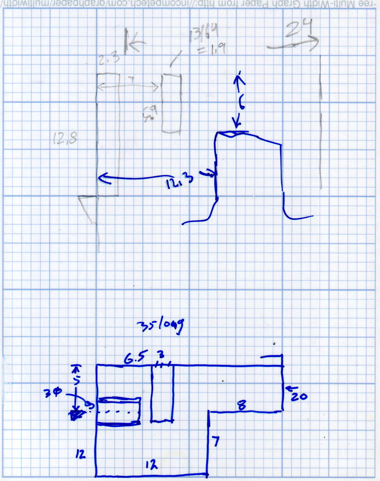
Which produced a sketch of the key dimensions:
Refrigerator Drawer Strut – Dimension Doodles
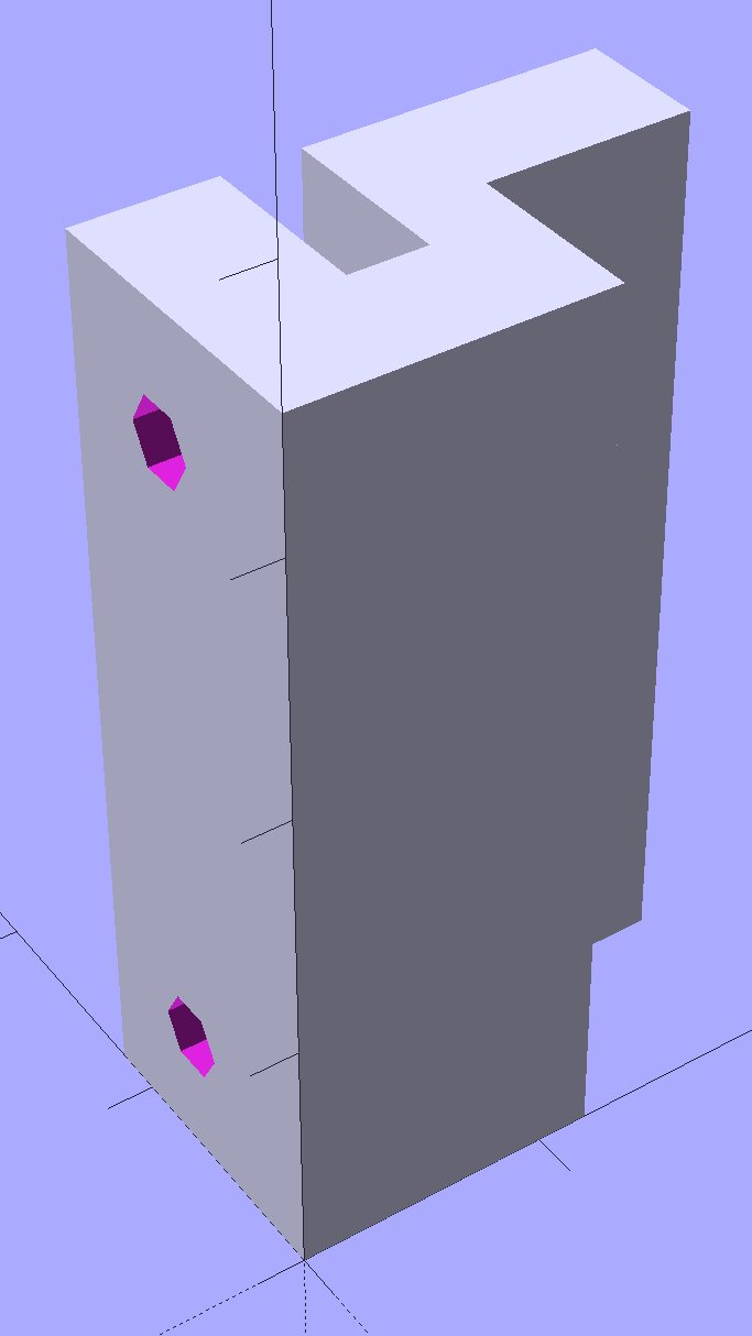
Which became an extruded polygon with a few holes punched in the side:
Refrigerator Shelf Strut Tab – solid model
Building it standing up wraps the plastic threads around the entire tab and stacks the layers along the length of the tab. Doing it lying down in the obvious hump-up orientation would put the layers parallel to the bottom surface, where they can pull apart under load.
The key innovation here involves being willing to assemble the tab to the strut in situ, without insisting it fit through the frame opening and be more-or-less easily removable. That let me bulk up the tab to match the end of the strut, fill the entire frame opening with plastic, and get enough bulk for a pair of 4-40 screws that, being loaded in shear, should withstand the weight of all those fruits & veggies in the drawers.
The screws simply thread into the holes in the tab, without benefit of tapping. The OpenSCAD code now includes a pair of nut traps, but I’m hoping they won’t be needed.
The new tab really does fill the space available:
Refrigerator Drawer Strut – new tab in place
The OpenSCAD code now moves the notch half a millimeter further away from the strut to center it over the ridge. What’s not obvious is how the frame slants toward the tab over the U-bar: the tab just barely clears and probably should have a tapered nose. You may add that if you like.
The U-shaped bar constrains the tab pretty firmly and supports the end, which should now be plump enough to withstand the forces involved. The screws sit horizontally with the frame installed and can’t pull out, which is why I think they can get along without nut traps.
It’s built in cyan PETG with three perimeter threads and 40% 3D Honeycomb fill, making it essentially a solid block of plastic; it’ll be interesting to see what fails next.
The OpenSCAD source code, which I hammered out in a white-hot fury:
// Refrigerator Shelf Strut Tab
// Ed Nisley KE4ZNU December 2015

//- Extrusion parameters must match reality!

ThreadThick = 0.25;
ThreadWidth = 0.40;

HoleWindage = 0.2;

Protrusion = 0.1;			// make holes end cleanly

inch = 25.4;

function IntegerMultiple(Size,Unit) = Unit * ceil(Size / Unit);

//----------------------
// Dimensions

TabSize = [20.0,12.0,35.0];							// length from bracket, height, width along front

SlotSize = [3.0,7.0];
SlotX = 7.0;

TabProfile = [
	[0,0],
	[12,0],	[12,7.0],
	[TabSize[0],7.0], [TabSize[0],TabSize[1]],
	[SlotX + SlotSize[0]/2,TabSize[1]],
	[SlotX + SlotSize[0]/2,5.0], [SlotX - SlotSize[0]/2,5.0],
	[SlotX - SlotSize[0]/2,TabSize[1]],
	[0,TabSize[1]]
];

ScrewY = 7.0;
ScrewOC = 25.0;
ScrewOD = 2.5;

NutOD = 6.6;					// across flats
NutThick = 2.5;

//----------------------
// Useful routines

module PolyCyl(Dia,Height,ForceSides=0) {			// based on nophead's polyholes

  Sides = (ForceSides != 0) ? ForceSides : (ceil(Dia) + 2);

  FixDia = Dia / cos(180/Sides);

  cylinder(r=(FixDia + HoleWindage)/2,
		h=Height,
	$fn=Sides);
}

//----------------------
// Build it

difference() {
	linear_extrude(height=TabSize[2],convexity=4)
		polygon(points=TabProfile);

	for (i=[-1,1]) {
		translate([-Protrusion,ScrewY,i*ScrewOC/2 + TabSize[2]/2])
			rotate([0,90,0])
				rotate(180/6)
					PolyCyl(ScrewOD,SlotX,6);
		translate([SlotX - SlotSize[0]/2 - NutThick - Protrusion,ScrewY,i*ScrewOC/2 + TabSize[2]/2])
			rotate([0,90,0])
				rotate(180/6)
					PolyCyl(NutOD,NutThick + SlotSize[0],6);
	}
}
Maybe that’ll last until we finally scrap out the refrigerator…
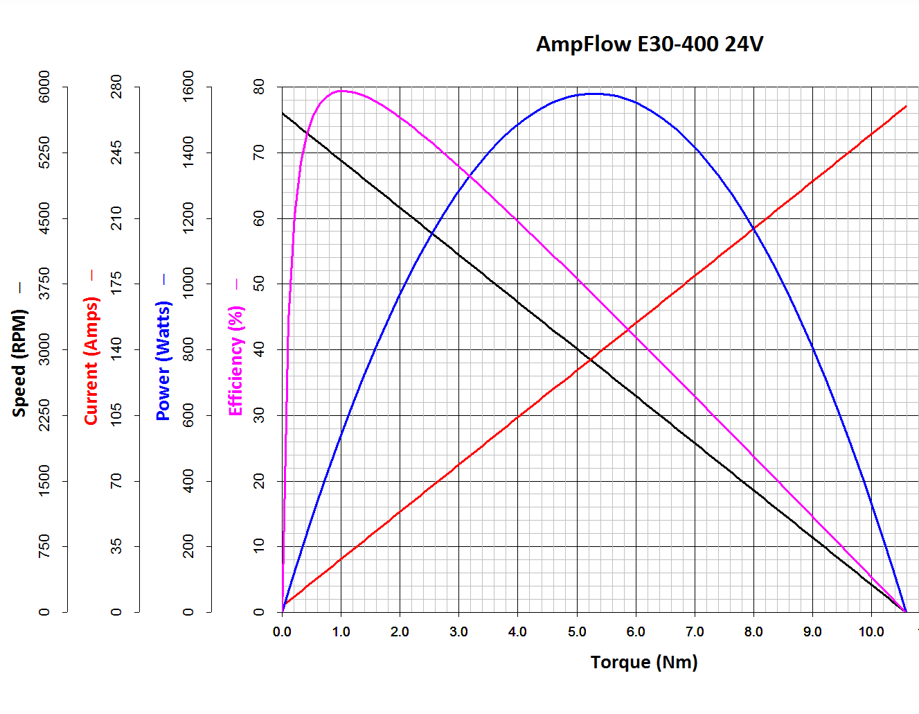
The Power Wheels Racer rules limit the motor to 1440 W, a tidy 60 A at 24 V. Let’s call it 70 A, which lines up neatly with the second major division up from the bottom: the orange current line hits 70 A with torque = 2.6 N·m.
Draw a vertical line at that point and read off all the other parameters from the scales on the left.
The motor will produce 2.6 N·m at just shy of 4500 RPM; call it 4400 RPM.
The SqWr Racer has 9:40 chain-drive gearing, so the rear wheels turn at:
990 RPM = 4400 RPM x (9/40)
With 13 inch diameter wheels, the racer moves at:
38 mph = 990 RPM x (π x 13 inch) x (60 min/hr) x (1 mile / 63.36x103 inch)
Which is scary fast if you ask me. A higher ratio may be in order.
At that speed the motor delivers: 1.6 HP = 1180 W = 2.6 N·m x 4400 RPM x 2π rad/rev / (60 s/min)
… to the shaft and, minus mechanical losses, to the tires.
If the racer doesn’t require that much power to roll at breakneck speed, it’ll go even faster, until the motor’s (falling) power output matches the (rising) mechanical load at some higher speed with correspondingly lower current.
With a current of 70 A and a winding resistance of 0.089 Ω (let’s say 0.10 Ω), the motor dissipates 490 W. That’s probably too much for long-term running, even with a 70% (= 1150 / (1150 + 490)) efficiency.
The mandated Littelfuse 60 A fuse has a bit under 1 mΩ of cold resistance and will dissipate 3.6 W at 60 A. The specs say it will blow within 6 minutes at rated current.
The resistance of the wiring / connectors / switches / whatever should be on that same order. Figuring the racer needs 2 m of stranded copper wire, that calls for 2 AWG or larger (0.5 mΩ/m). Right now, the racer uses 8 AWG (2 mΩ/m) and might have 4 mΩ total resistance, although I think it has less than 2 m of wire. Empirically, the motor conductors get really hot at 40 A for about ten seconds, but that’s with a severely defunct motor.
If the conductors + connectors between the battery and the motor introduce, say, 10 mΩ of resistance, they’ll dissipate 36 W at 60 A. That scales linearly with resistance, so a high-resistance connection will incinerate itself.
Using a PWM controller to reduce the speed will reduce the available horsepower, so the racer will accelerate slowly. With the torque limited to 2.6 N·m, the horsepower will vary linearly with the PWM duty cycle: nearly zero for small PWM, up to 1.5 HP for large PWM at 60 A, then upward as the RPM increases with decreasing load. Yeah, you get more torque when you need it least.
I could make a case for a three-speed transmission in addition to higher gear ratio, although that seems overly complex.
A less beefy motor will be in order and The Mighty Thor suggests a torque converter as a low-budget transmission. Sounds good to me; I should learn more about electric traction motors…
The Power Wheels Racer taking shape at SquidWrench let out The Big Stink at the Mini Maker Faire a few weeks ago, so I brought some test equipment to the regular Weekly Doing and helped with the autopsy.
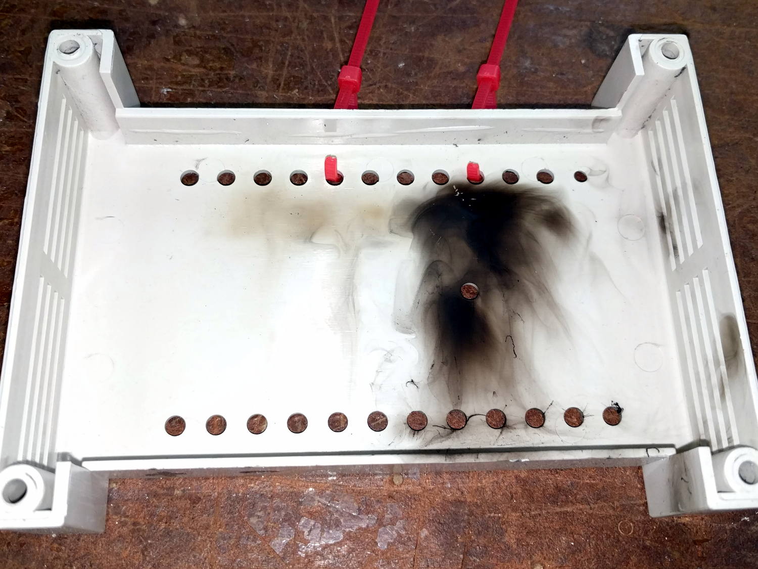
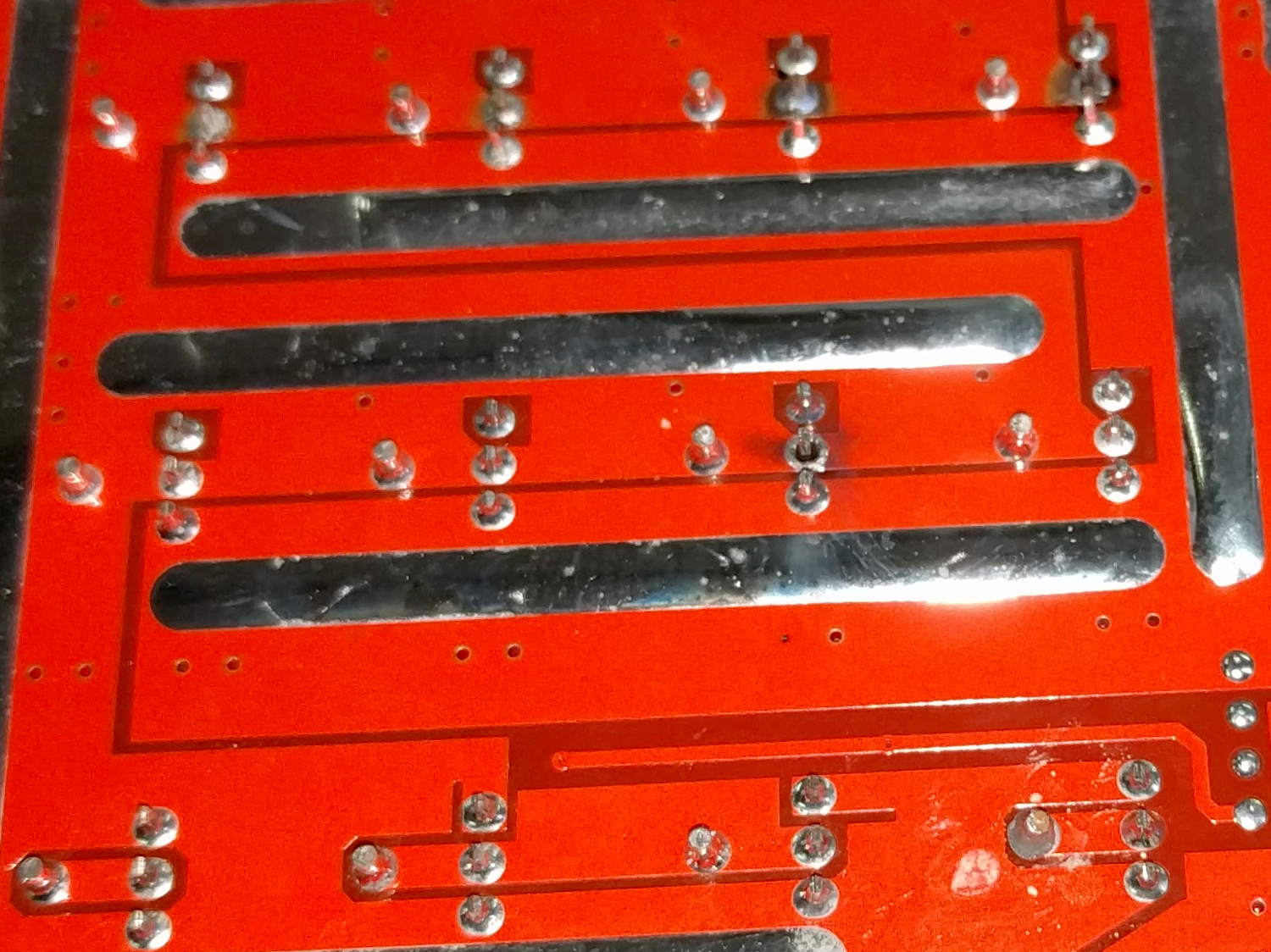
The PWM motor controller purports to do 60 A at up to 50 V, but removing the cover showed it wasn’t going to do any more controlling:
Motor Controller – smoked housing
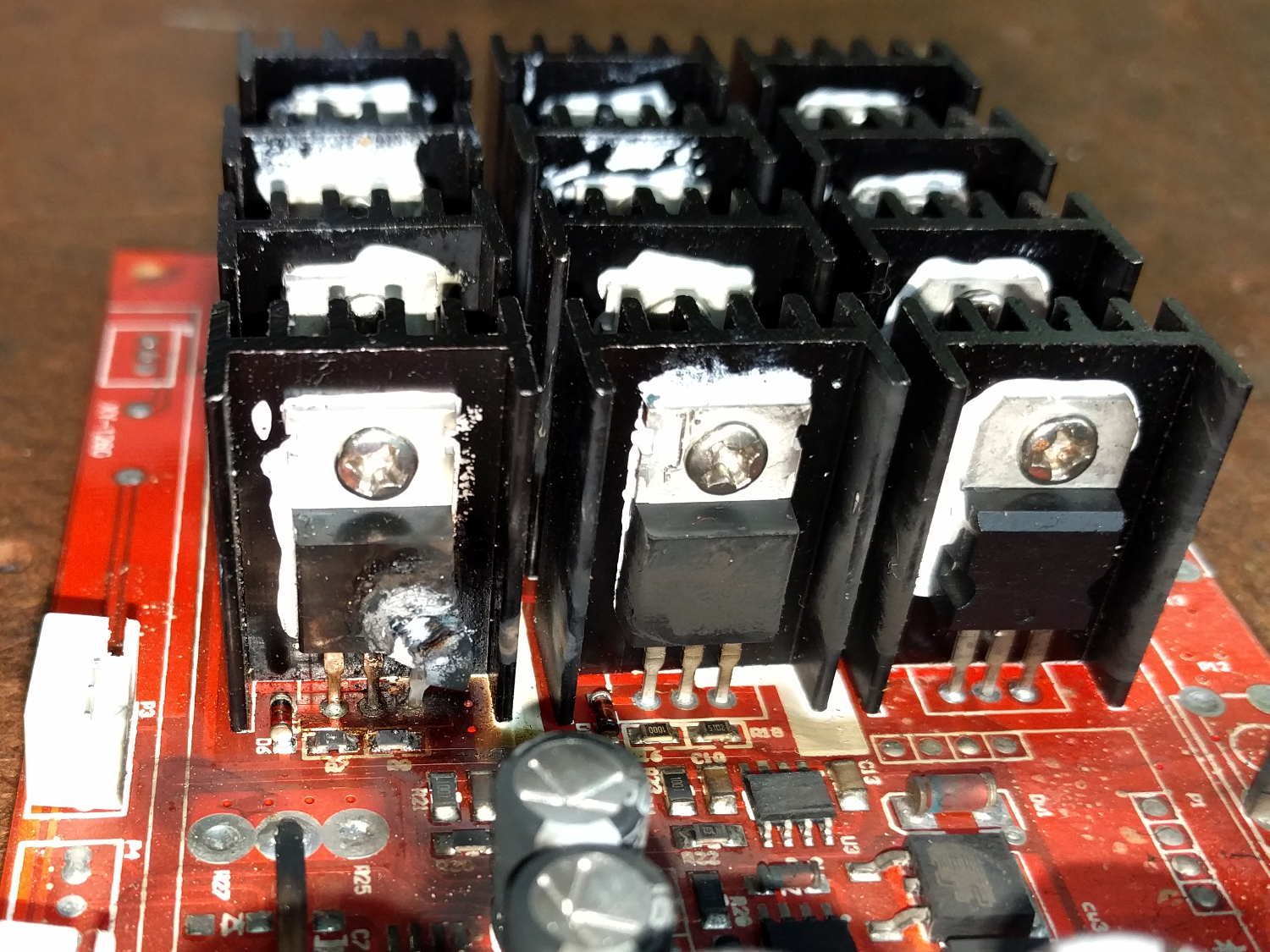
That smudge came from a rank of detonated MOSFETs:
Motor Controller – exploded MOSFET
Other MOSFETs had unsoldered themselves:
Motor Controller – unsoldered MOSFETs
Explosively:
Motor Controller – solder ejecta
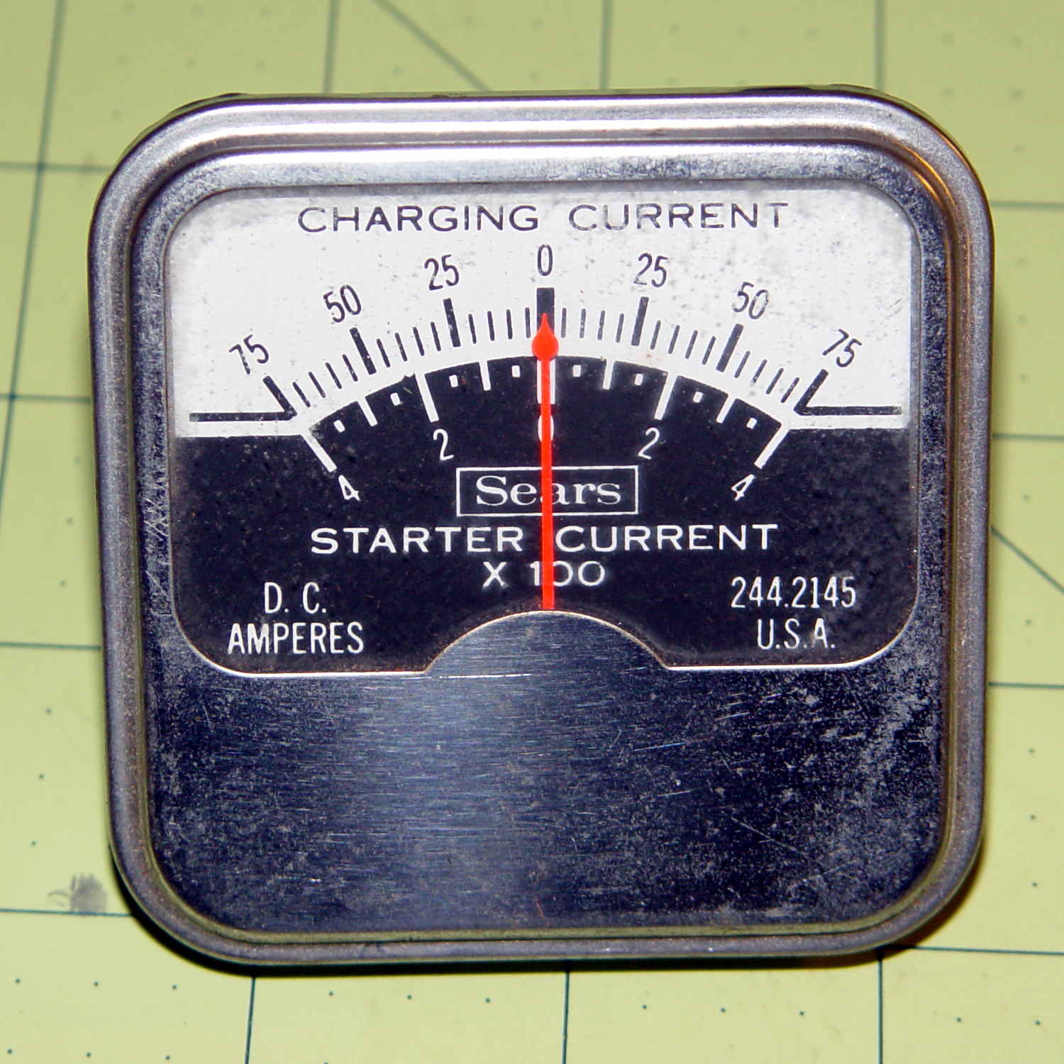
I brought along an ancient Sears starter-motor ammeter to measure the motor current:
Sears 244-2145 Starter Ammeter – front
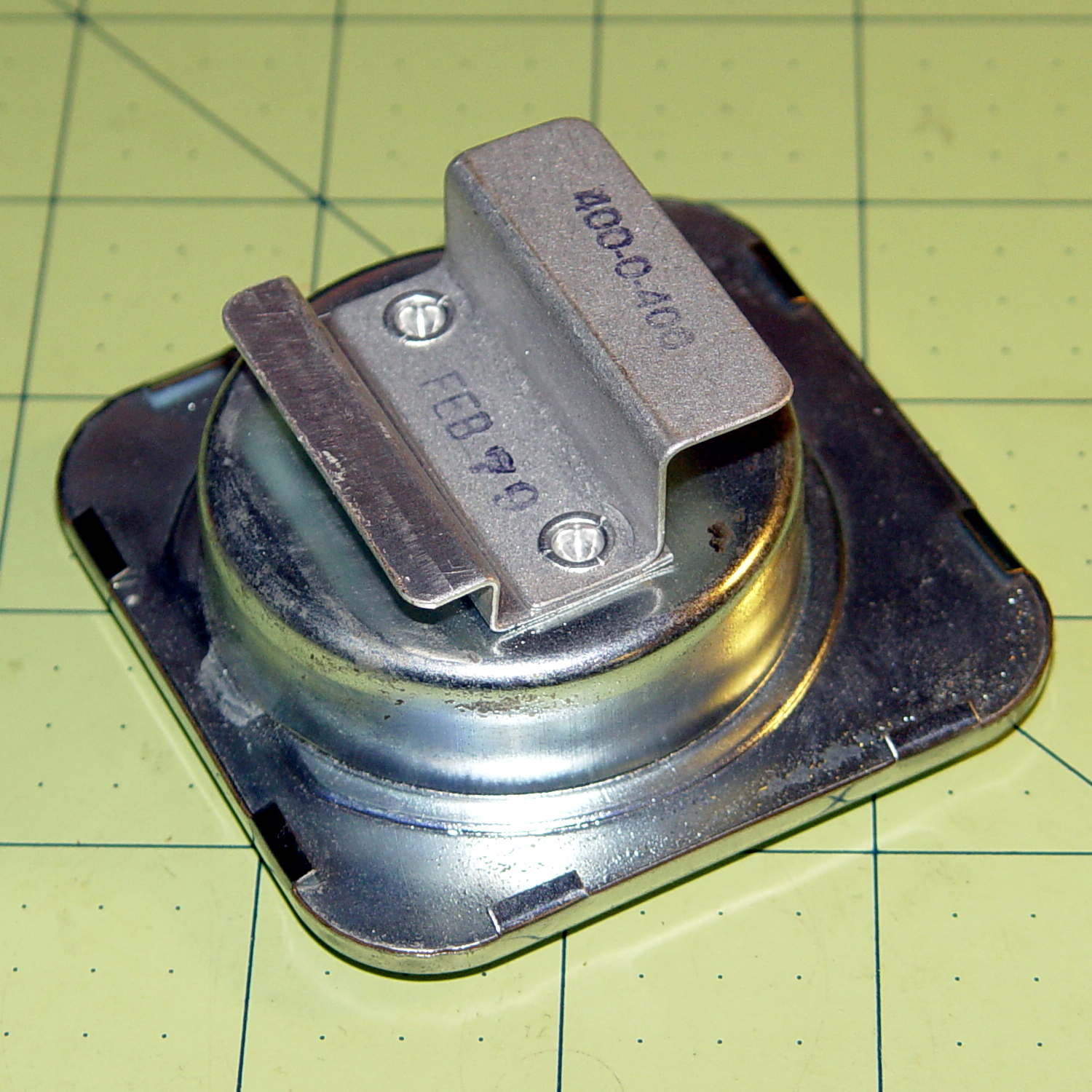
The magnetic field around the wire directly drives the meter movement, with two guides for the 75 A and 400 A ranges, and none of that newfangled Hall effect nonsense to contend with:
Sears 244-2145 Starter Ammeter – wire guides
Yeah, that says FEB 79; I’ve been collecting tools for quite a while…
I slapped the motor connectors directly on the battery terminals, holding them with small locking pliers after discovering that the wires got way too hot, way too fast. A snippet of retroreflective tape on the motor sprocket and a laser tach gave us the speed:
12 V: 1600 RPM @ 40 A
24 V: 2400 RPM @ > 100 A
The AmpFlow E30-400 motor data sheet confirmed that those numbers were grossly wrong. Unloaded, it should spin at 5700 RPM at 24 V while drawing 3.2 A (thus, 2800 RPM at 12 V & 1.6 A).
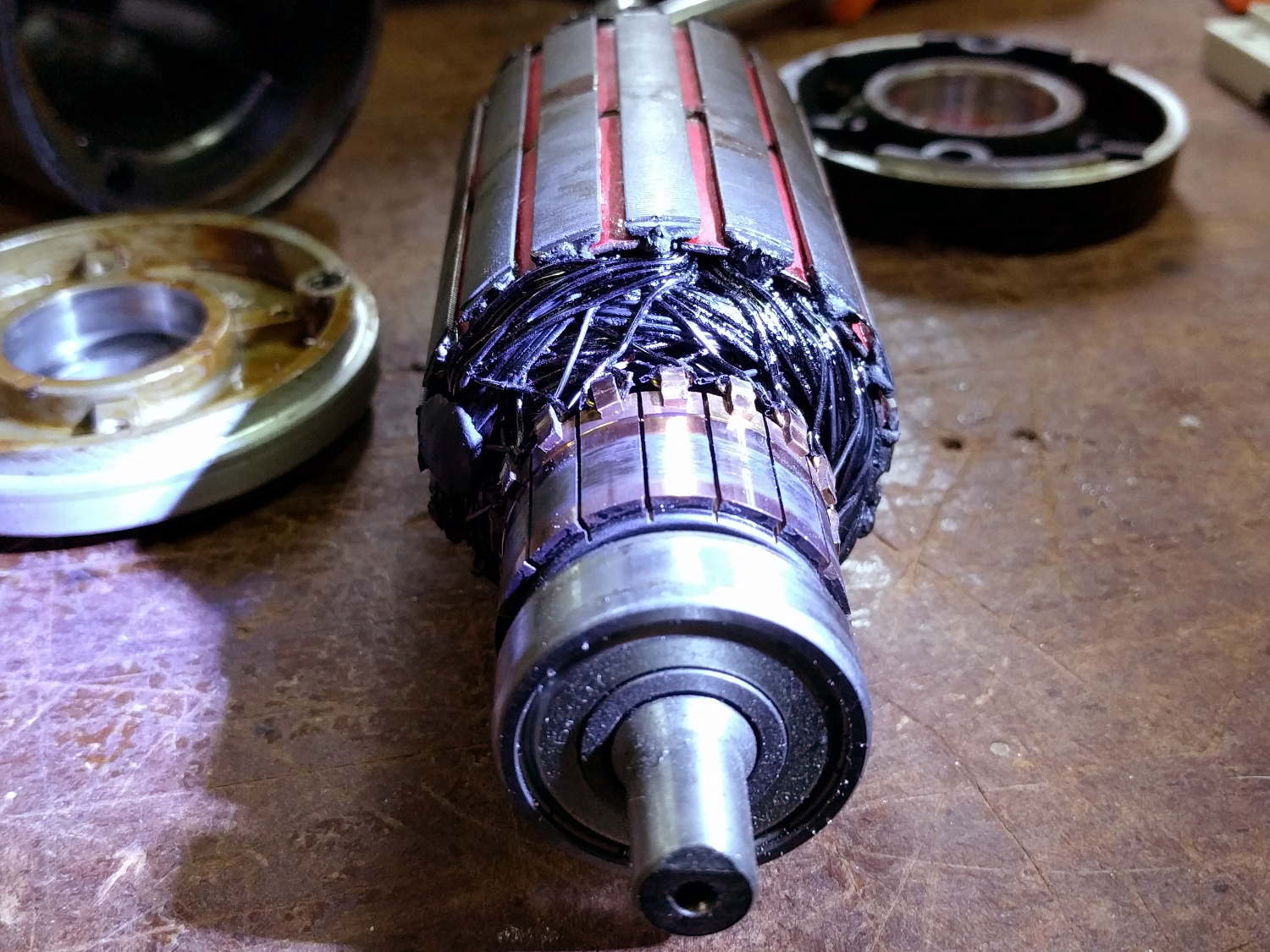
Diassembling the motor showed it hadn’t escaped the carnage:
Motor – charred windings
Those windings should be the usual amber enamel-over-copper, not charred black. The excessive current and reduced speed suggests many shorted turns inside the rotor.
Protip: never disassemble a working DC motor, because you’ll demagnetize the stator. The motor should still run when you put it back together, but the reduced magnetic field will wreck the performance.
As nearly as we could tell, one of the motor wires shorted to the frame when it got pinched under the seat; that’s an easy mistake to make and shows why compulsive wire neatness pays off big time. Shorting the controller output blew the transistors and, after raising the seat to look underneath, the motor would cook itself without generating much torque while you figure out what happened.
As far as I’m concerned, if you’ve never blown up anything that severely, you’re not building interesting stuff and definitely not trying hard enough.
The next iteration should work better!
Thanks to Dragorn of Kismet for stepping into the stench with phone camera in hand…
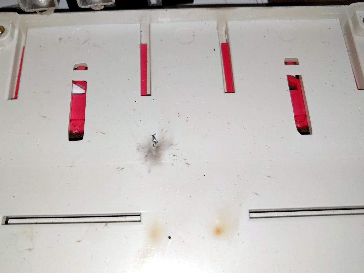
The Epson R380 started making an odd thwapping noise, which turned out to be the ink tubes from the Continuous Ink Supply System slapping the overly complex interior of the printer. They seemed a bit loose, but it took some searching before I found the top of the clamp that holds them in place:
Epson R380 CISS hose clamp – broken
It’s the white rectangle nestled in front of the ink cartridges, where it fits perfectly into a convenient slot and looks like it grew there.
I briefly considered 3D printing a replacement, but came to my senses:
Epson R380 CISS hose clamp – fixed
That should be good until the silicone rubber tubes finally break after a bazillion flex cycles…
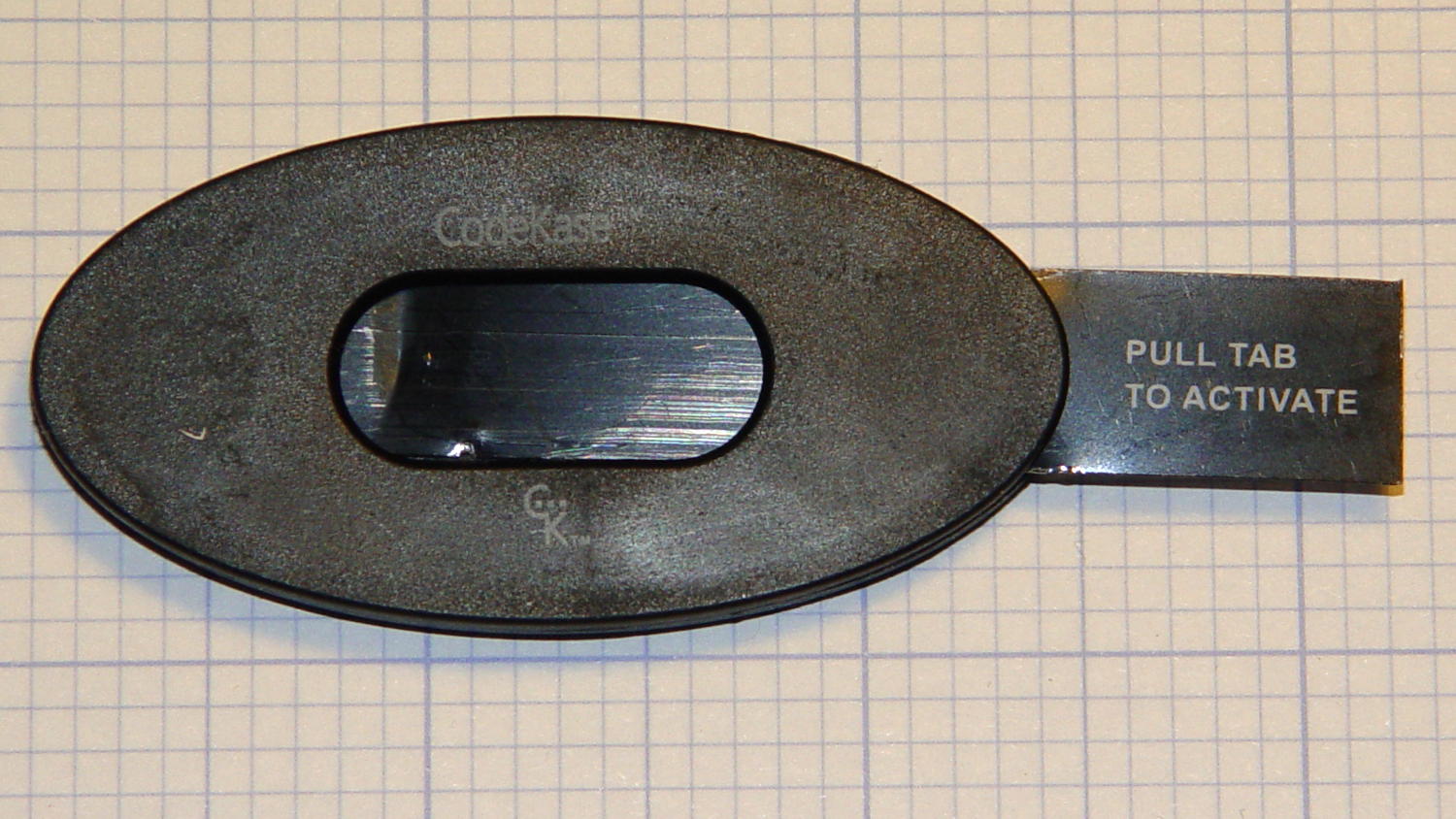
So this device showed up in an envelope with a letter telling us we’d won a contest if, of course, the number on the device matched the number in the letter:
CodeKase device
I wonder if anybody else had second thoughts about pulling what’s obviously an insulating sheet holding two contacts apart? In this day and age, getting the victim to blow his own fingers off probably counts as a win.
Maybe it comes from having read The White Plague at an impressionable age. Who could resist getting a Nice Thing in the mail?
The number matched, of course, but the letter’s finer print said the prize would be one of:
A new car of some sort
A flat screen TV
A cheap electronic trinket
A three-day / two night vacation
In order to claim your prize, you had to call an 800 number. The much finer print revealed the odds of winning the first three of those prizes was somewhere around 300,000:1. “Winning” the vacation was essentially a slam-dunk proposition, of course, and probably tells you everything you need to know about the course of the phone call.
It’s apparently economical to send out this much hardware to reel in new “customers”:
CodeKase device – parts
Using the metal disk from a membrane switch as a spring to push the coin cell against the contact wires is a nice touch. This is apparently the optimized version that uses a single lithium cell in place of two alkaline buttons; the cell “socket” on the other end consists of vestigial lumps.
I harvested the lithium cell and the blue LED, of course…
More about CodeKase, direct from the source. I like “Step Five: Recycle Your CodeKase”…
Mary started doing “ruler quilting” that involves sewing seams aligned with templates, only to find that the thumbscrew holding the (modified) presser foot obscures the view to the left of the needle:
Kenmore Model 158 – OEM Presser Foot Screw
The screw looked to be 6-32 and I wanted to use a socket head cap screw, but thread turns out to be 6-40. Having previously bought the Brownell’s Fillister Head Screw Assortment specifically to solve that problem, all I had to do was cut the screw to length:
Kenmore Model 158 – Small Presser Foot Screw
The washer epoxied to the screw provides a bit more bearing surface.
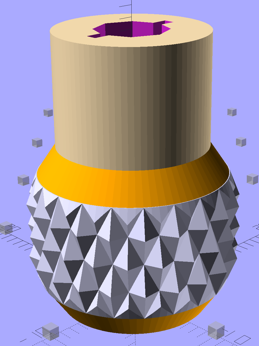
Rather than putz with a screwdriver, this handle locates itself around the screw head; turn until the blade clicks into the screw slot, then tighten or loosen as needed:
Kenmore Model 158 – Presser Foot – Driver and Screw
The slot holds a chunk of spring steel (barely visible in the driver’s snout in group photo above) that accounts for the fat shaft around the screw head:
Presser Foot Screw Driver – top – Slic3r
I think the shaft could be a few millimeters narrower, but a bit of meat around the ends of the blade will support it against the torque.
The screw head slot is about 1 mm and the blade is 0.75 mm. I chopped the blade to fit by whacking the spring with a poorly tempered cold chisel, then flexing across the impact line until it broke. That chisel needed sharpening anyhow.
A dab of epoxy along the slot edges holds the blade in place. I inserted it flush with the top of the socket, then lined up the screw and pushed, with the steel bottomed out in the screw head and riding down for a perfect fit.
Then it’s all good!
The OpenSCAD source code:
// Presser Foot Screw Driver for Kenmore Model 158
// Ed Nisley - KE4ZNU - December 2015

use <knurledFinishLib_v2.scad>

//- Extrusion parameters must match reality!
//  Print with 2 shells and 3 solid layers

ThreadThick = 0.20;
ThreadWidth = 0.40;

HoleWindage = 0.3;			// extra clearance to improve hex socket fit

Protrusion = 0.1;			// make holes end cleanly

inch = 25.4;

//----------------------
// Dimensions

SocketDia = 5.75;				// generous fit on 6-40 fillister screw head
SocketDepth = 3.2;

Blade = [9.0,1.0,ceil(SocketDepth + 5)];		// inserted metal driver blade
echo(str("Blade: ",Blade));

ShaftDia = 1.5*Blade[0];		// un-knurled section diameter
ShaftLength = 10.0;				//  ... length

KnurlLen = 10.0;				// length of knurled section
KnurlDia = 18.0;				//   ... diameter at midline of knurl diamonds
KnurlDPNom = 30;				// Nominal diametral pitch = (# diamonds) / (OD inches)

DiamondDepth = 1.0;				//   ... depth of diamonds
DiamondAspect = 2;				// length to width ratio

KnurlID = KnurlDia - DiamondDepth;		// dia at bottom of knurl

NumDiamonds = ceil(KnurlDPNom * KnurlID / inch);
echo(str("Num diamonds: ",NumDiamonds));

NumSides = 4*NumDiamonds;		// 4 facets per diamond

KnurlDP = NumDiamonds / (KnurlID / inch);				// actual DP
echo(str("DP Nom: ",KnurlDPNom," actual: ",KnurlDP));

DiamondWidth = (KnurlID * PI) / NumDiamonds;

DiamondLenNom = DiamondAspect * DiamondWidth;					// nominal diamond length
DiamondLength = KnurlLen / round(KnurlLen/DiamondLenNom);		//  ... actual

TaperLength = 0.50*DiamondLength;

KnobOAL = 2*TaperLength + KnurlLen + ShaftLength;

//----------------------
// Useful routines

module PolyCyl(Dia,Height,ForceSides=0) {			// based on nophead's polyholes

  Sides = (ForceSides != 0) ? ForceSides : (ceil(Dia) + 2);

  FixDia = Dia / cos(180/Sides);

  cylinder(r=(FixDia + HoleWindage)/2,
           h=Height,
	   $fn=Sides);
}

module ShowPegGrid(Space = 10.0,Size = 1.0) {

  Range = floor(50 / Space);

	for (x=[-Range:Range])
	  for (y=[-Range:Range])
		translate([x*Space,y*Space,Size/2])
		  %cube(Size,center=true);
}


//- Build it

ShowPegGrid();

difference() {
	union() {
		render(convexity=10)
		translate([0,0,TaperLength])			// knurled cylinder
			knurl(k_cyl_hg=KnurlLen,
				  k_cyl_od=KnurlDia,
				  knurl_wd=DiamondWidth,
				  knurl_hg=DiamondLength,
				  knurl_dp=DiamondDepth,
				  e_smooth=DiamondLength/2);
		color("Orange")							// lower tapered cap
		cylinder(r1=ShaftDia/2,
					r2=(KnurlDia - DiamondDepth)/2,
					h=(TaperLength + Protrusion),
					$fn=NumSides);
		color("Orange")							// upper tapered cap
		translate([0,0,(TaperLength + KnurlLen - Protrusion)])
			cylinder(r2=ShaftDia/2,
					r1=(KnurlDia - DiamondDepth)/2,
					h=(TaperLength + Protrusion),
					$fn=NumSides);
		color("Moccasin")						// cylindrical extension
		translate([0,0,(2*TaperLength + KnurlLen - Protrusion)])
			cylinder(r=ShaftDia/2,h=(ShaftLength + Protrusion),$fn=NumSides);

	}

	translate([0,0,(KnobOAL - SocketDepth + Protrusion)])
		PolyCyl(SocketDia,(SocketDepth + Protrusion),8);	// screw head socket

	translate([0,0,KnobOAL - (Blade[2] - Protrusion)/2])
		cube(Blade + [0,0,Protrusion],center=true);
}