
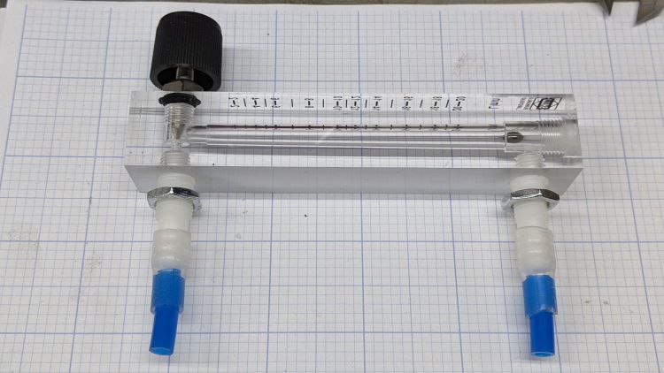
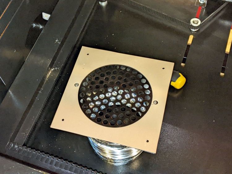
With the solid state relay switching the air assist pump, an air flowmeter seemed like it would come in handy:

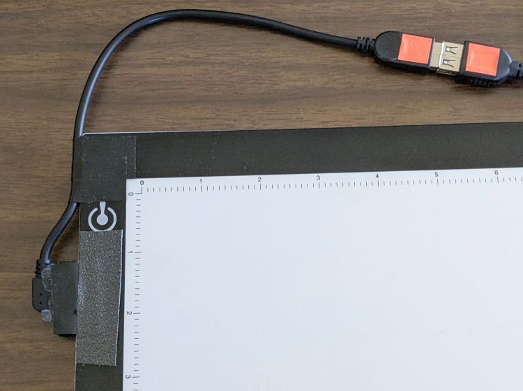
It’s stuck to the lip inside the top hatch on the right side of the cabinet, which may not be the most convenient location, but keeps it out of the way and doesn’t require much additional tubing.
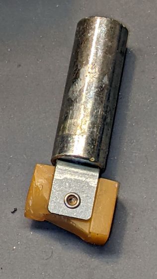
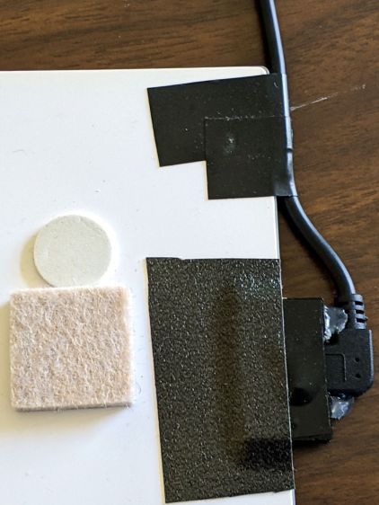
The 6 mm tube kit included some (1/8 NPT?) push fittings that came heartbreakingly close to matching the flowmeter’s internal threads:

Given that the air pump doesn’t produce much pressure, two snippets of 1/4 inch silicone tubing suffice to couple the blue 6 mm tubing to the flowmeter’s barbs:
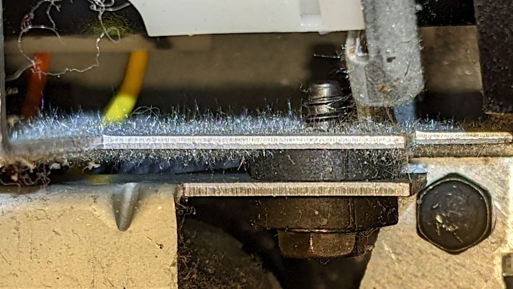
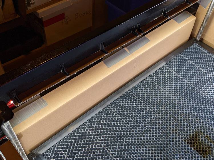
The run from the air pump to the flowmeter is now new blue tubing, with the original black tubing running through the drag chain to the laser nozzle:

Replacing a number of overly tight cable ties along the way may remove enough restrictions to counterbalance the additional tubing.
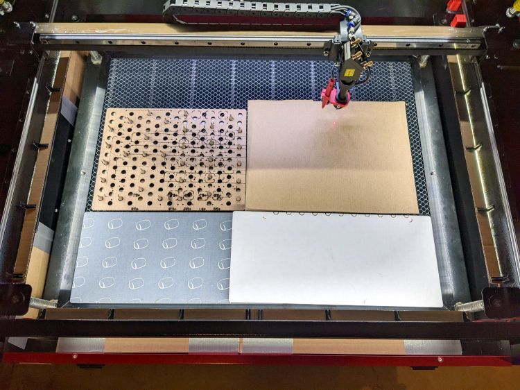
Opening the flowmeter’s valve all the way puts 14 l/m = 0.5 CFM through the nozzle. I have no idea of the proper rate, other than more is better while cutting and less is better for engraving.
Four years ago, Russ Sadler laid out the plumbing required to automatically select high and low flow air assist, which seems like a worthwhile project.


