The Smell of Molten Projects in the Morning

Ed Nisley's Blog: Shop notes, electronics, firmware, machinery, 3D printing, laser cuttery, and curiosities. Contents: 100% human thinking, 0% AI slop.

Tag: Sherline

Sherline CNC mill

  • Tek Circuit Computer: V Engraved Hairlines

    Tek Circuit Computer: V Engraved Hairlines

    Without much in the way of fixturing, a small V engraving bit cuts surprisingly nice hairlines:

    Hairline tests - V tool 4 kRPM 12 24 IPM - full crop
    Hairline tests – V tool 4 kRPM 12 24 IPM – full crop

    It’s an anonymous HSS bit similar to the fancy ones with “blue nano” or “titanium” coatings, which I’m sure have the same effectiveness as the “gold” coating on audio plugs and jacks.

    The tip is pretty close to the stated 0.1 mm. The included V angle looks like 22.5°, but the descriptions use the half angle, so it’s either a generous 10° or a scant 15°, take your pick.

    It’s turning at 4000 RPM in the Sherline spindle, which is much too slow for such a tiny cut. No coolant, nothing fancy.

    The lower left group ran at increasing depths from 0.0 to about 0.6 mm, with the deepest one looking surprisingly good.

    It’s all manual jogging at either 12 or 24 inch/min and, when you (well, I) count the swirls across those 100 mil grids, the spindle really is turning at 4 kRPM. Gotta love it when the numbers work out!

    These are obviously the best-looking hairlines yet, so I must tweak the GCMC source to do the right thing with the existing fixture.

  • Tek Circuit Computer: Sawed Hairline Fixture

    Tek Circuit Computer: Sawed Hairline Fixture

    This is a fixture to hold a cursor for an Homage Tektronix Circuit Computer while a tiny circular saw blade cuts a narrow flat-bottomed trench:

    Tek CC - sawed cursor - Sherline setup
    Tek CC – sawed cursor – Sherline setup

    Each of the 123 blocks is held to the Sherline tooling plate with a 10-32 SHCS in a little aluminum pin, with another threaded pin for the screw holding the fixture on the side. The minimal top clearance provided some of the motivation behind making those pins in the first place; there’s no room for the usual threaded stud sticking out of the block with a handful of washers under the nut.

    The fixture has locating slots (scribbled with black Sharpie) to touch off the spindle axis and the saw blade at the XZ origin at the pivot hole center. Touching off the saw blade on the cursor surface sets Y=0, although only a few teeth will go ting, so the saw must be spinning.

    I cut the first slot under manual control to a depth of 0.3 mm on a scrap cursor with a grotty engraved hairline:

    Tek CC - first sawed cursor - detail
    Tek CC – first sawed cursor – detail

    It looks better than I expected with some red lacquer crayon scribbled into it:

    Tek CC - first sawed cursor - vs scribed
    Tek CC – first sawed cursor – vs scribed

    A few variations of speed and depth seem inconclusive, although they look more consistent and much smoother than the diamond-drag engraved line with red fill:

    Tek CC - sawed cursor test - magnified
    Tek CC – sawed cursor test – magnified

    The saw produces a ramp at the entry and exit which I don’t like at all, but the cut is, overall, an improvement on the diamond point.

    The OpenSCAD source code as a GitHub Gist:

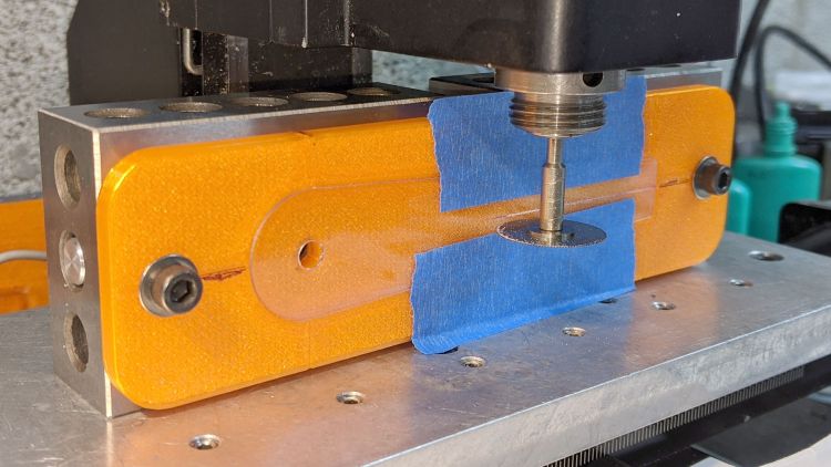
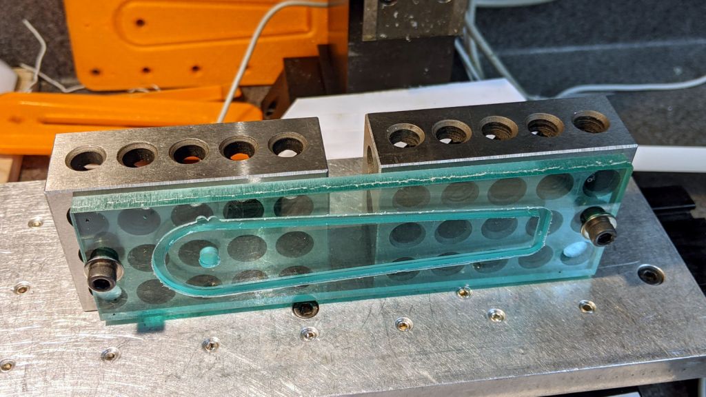
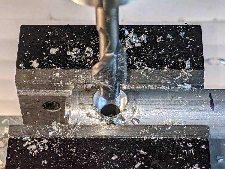
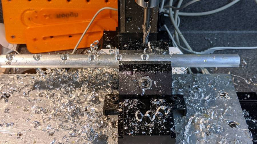
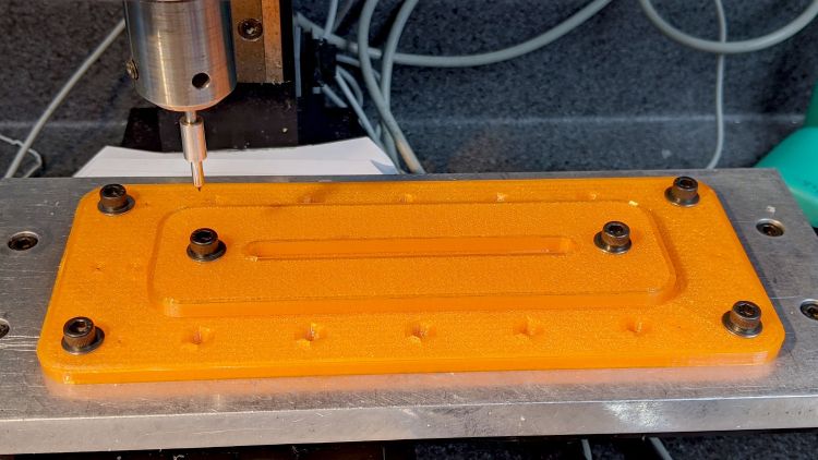
    // Sawing fixtures for Tek Circuit Computer cursor hairline
    // Ed Nisley KE4ZNU Jan 2021
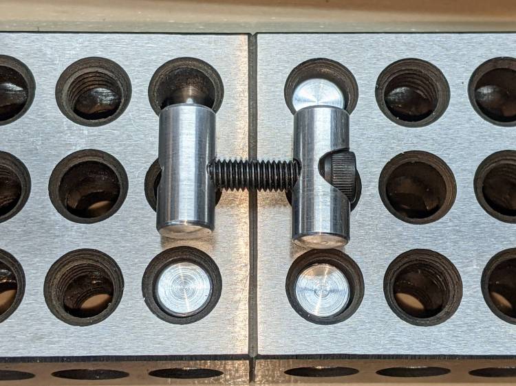
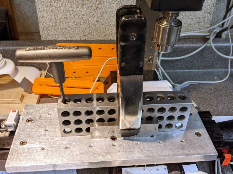
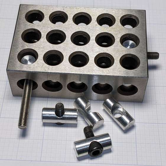
    // Rotated 90° and screwed to 123 blocks for sawing
    Layout = "Show"; // [Show, Build, Cursor]
    Gap = 4.0;
    /* [Hidden] */
    ThreadThick = 0.25;
    ThreadWidth = 0.40;
    HoleWindage = 0.2;
    Protrusion = 0.1; // make holes end cleanly
    inch = 25.4;
    function IntegerMultiple(Size,Unit) = Unit * ceil(Size / Unit);
    module PolyCyl(Dia,Height,ForceSides=0) { // based on nophead's polyholes
    Sides = (ForceSides != 0) ? ForceSides : (ceil(Dia) + 2);
    FixDia = Dia / cos(180/Sides);
    cylinder(d=(FixDia + HoleWindage),h=Height,$fn=Sides);
    }
    //———————-
    // Dimensions
    CursorHubOD = 1.0*inch; // must match SVG hub OD
    CursorThick = 0.71; // including protective layers
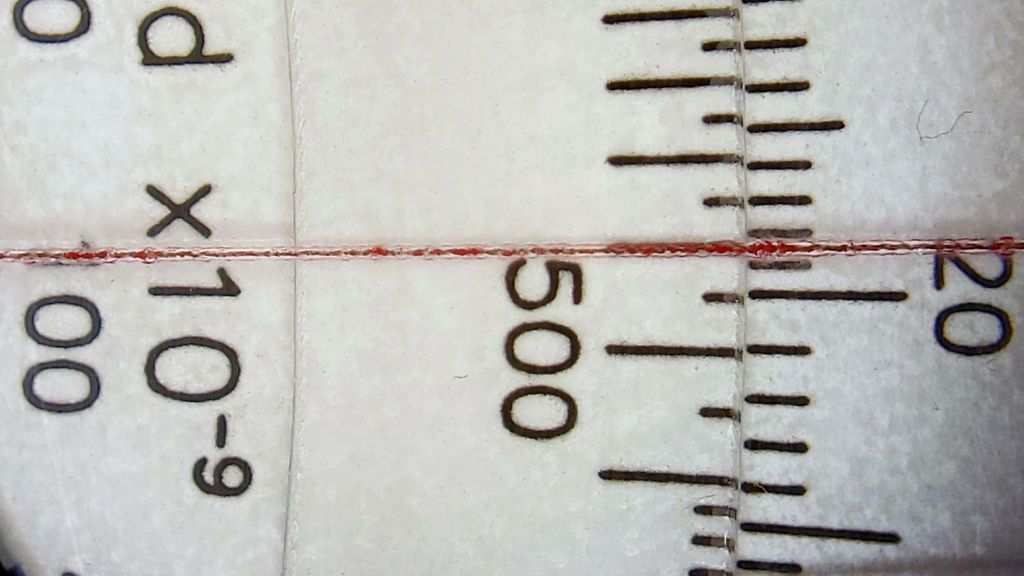
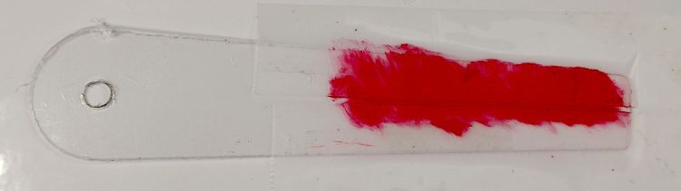
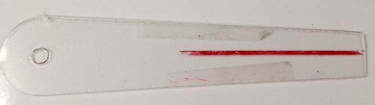
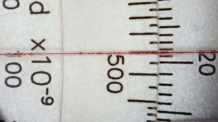
    HairlineMin = 48.4188; // extent of hairline
    HairlineMax = 97.4250;
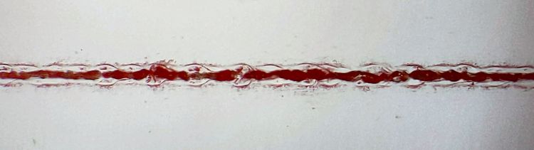
    HairlineDepth = 0.20;
    PocketDepth = 0.75*CursorThick; // half above surface for taping
    PocketClear = 0.25; // E-Z insertion clearance
    TableOC = [1.16*inch,1.16*inch]; // Sherline tooling plate grid
    BlockOC = [(9/16)*inch,(9/16)*inch]; // 123 block hole grid
    BlockOffset = [(3/8)*inch,(3/8)*inch]; // .. block edge to hole center
    ScrewClear = 5.0; // … screw clearance
    CursorOffset = [2*BlockOC.x,0,0]; // hub center relative to leftmost screw
    FixtureGrid = [5*TableOC.x,0,0]; // size in Table grid units
    Screws = [ // relative to leftmost screw
    [0,0,0], // on table grid
    CursorOffset, // on block grid
    [FixtureGrid.x,0,0] // on table grid
    ];
    echo(str("Screw centers: ",Screws));
    CornerRad = 10.0; // corner radius
    Fixture = [2*CornerRad + FixtureGrid.x,2*CornerRad + CursorHubOD,5.0];
    echo(str("Fixture plate: ",Fixture));
    //———————-
    // Import SVG of cursor outline
    // Requires our CursorHubOD to match actual cut outline
    // Hub center at origin
    module CursorSVG(t=CursorThick,ofs=0.0) {
    hr = CursorHubOD/2;
    translate([-hr,-hr,0])
    linear_extrude(height=t,convexity=3)
    offset(r=ofs)
    import(
    file="/mnt/bulkdata/Project Files/Tektronix Circuit Computer/Firmware/TekCC-Cursor-Mark.svg",
    center=false);
    }
    //———————-
    // Show-n-Tell cursor
    module Cursor() {
    difference() {
    CursorSVG(CursorThick,0.0);
    translate([0,0,-Protrusion])
    rotate(180/6)
    PolyCyl(ScrewClear,CursorThick + 2*Protrusion,6);
    }
    }
    //———————-
    // Sawing fixture for cursor hairline
    // Plate center at origin
    module Fixture() {
    difference() {
    hull() // basic plate shape
    for (i=[-1,1], j=[-1,1])
    translate([i*(Fixture.x/2 – CornerRad),j*(Fixture.y/2 – CornerRad),0])
    cylinder(r=CornerRad,h=Fixture.z,$fn=24);
    translate([0,0,Fixture.z – ThreadThick/2 + Protrusion/2]) // will be Z=0 index
    cube([2*Fixture.x,ThreadWidth,ThreadThick + Protrusion],center=true);
    translate(-FixtureGrid/2) {
    translate(CursorOffset + [0,0,Fixture.z – 2*PocketDepth])
    difference() {
    CursorSVG(2*PocketDepth + Protrusion,PocketClear);
    CursorSVG(PocketDepth + Protrusion,-PocketClear);
    }
    translate([CursorOffset.x,0,Fixture.z – ThreadThick/2 + Protrusion/2]) // will be front X=0 index
    cube([ThreadWidth,2*Fixture.y,ThreadThick + Protrusion],center=true);
    translate([CursorOffset.x,Fixture.y/2 – ThreadThick/2 + Protrusion/2,0]) // will be top X=0 index
    cube([ThreadWidth,ThreadThick + Protrusion,2*Fixture.z],center=true);
    translate([CursorOffset.x + HairlineMin,0,Fixture.z – ThreadThick/2 + Protrusion/2]) // hairline min
    cube([ThreadWidth,2*Fixture.y,ThreadThick + Protrusion],center=true);
    translate([CursorOffset.x + HairlineMax,0,Fixture.z – ThreadThick/2 + Protrusion/2]) // hairline min
    cube([ThreadWidth,2*Fixture.y,ThreadThick + Protrusion],center=true);
    /*
    # translate(CursorOffset + [0,0,Fixture.z – 2*ThreadThick]) { // alignment pips
    for (x=[-20.0,130.0], y=[-30.0,0.0,30.0])
    translate([x,y,0])
    cylinder(d=4*ThreadWidth,h=1,$fn=6);
    # for (x=[-30.0,130.0,150.0])
    translate([x,0,0])
    cylinder(d=4*ThreadWidth,h=1,$fn=6);
    */
    for (pt=Screws)
    translate(pt + [0,0,-Protrusion])
    rotate(180/6)
    PolyCyl(ScrewClear,Fixture.z + 2*Protrusion,6);
    }
    }
    }
    //———————-
    // Build it
    if (Layout == "Cursor") {
    Cursor();
    }
    if (Layout == "Show") {
    rotate([0*90,0,0]) {
    Fixture();
    color("Green",0.3)
    translate(-FixtureGrid/2 + CursorOffset + [0,0,Fixture.z + Gap])
    Cursor();
    }
    }
    if (Layout == "Build"){
    // rotate(90)
    Fixture();
    }
  • 123 Block Links: Blackened!

    123 Block Links: Blackened!

    While looking for something else, I came across my bottle of Aluminum Black, so I just had to do this:

    123 Block Links - blackened
    123 Block Links – blackened

    Looks much snappier than the originals:

    123 Block Links - trial assembly
    123 Block Links – trial assembly

    Those are plain old alloy steel cap screws with a black oxide finish.

    The Aluminum Black package directions tell you to apply it with a swab, rinse, and repeat, which seemed like a lot of work for a handful of pins. Instead, I poured a little into a pill bottle, dumped the pins in, and gave it a good shake to coat the pins, whereupon the cap blew off as the contents proceeded to boil merrily. A quick cold-water rinse calmed things down, with no particular harm done, although I had to chase the threads with a tap to get the black powder out. A layer of oil prettied them up nicely.

    Today I Learned: the reaction between selenium dioxide and bare aluminum is strongly exothermic.

  • 123 Block Links: Sherline Tooling Plate

    123 Block Links: Sherline Tooling Plate

    Because the 123 block hole spacing doesn’t match the Sherline tooling plate’s 1.16 inch screw hole grid, each block has only a single 10-32 SHCS holding it down through a cap screw head pin:

    123 Block Links - Sherline table alignment
    123 Block Links – Sherline table alignment

    The spring clamp squashes a pair of reasonably straight steel bars against the blocks, whereupon gentle tightening can produce perfect Good Enough™ alignment.

    You could remove the tooling plate and attach the blocks directly to the Sherline’s table with two (or more!) T-nuts and screws per block. I expect no standard SHCS length would be quite right for the distance between the head held in the block pin and the T-nut in the table slot, not to mention removing and reinstalling the tooling plate is enough of a nuisance I’d rather not do it without good reason.

    Just to see how things looked, I attached the cursor milling fixture with threaded block pins:

    123 Block Links - Sherline layout
    123 Block Links – Sherline layout

    Note that the remaining 10-32 clearance hole in the fixture (for the cursor hub) doesn’t align with the underlying hole in the block; the next fixture must take into account both the Sherline and the 123 block grids, as well as which block holes align with the tooling plate. Bleh!

  • 123 Block Links: Threaded Pins

    123 Block Links: Threaded Pins

    The pins capturing the SHCS heads will mount the 123 blocks to the Sherline’s table or tooling plate, but attaching things to the blocks or joining them requires threaded pins on the other end of the screws:

    123 Block Links - trial assembly
    123 Block Links – trial assembly

    Optical illusion: those two pins are the same length.

    I grabbed a length of 3/8 inch aluminum rod in the Sherline vise, center-drilled four holes spaced 7/8 inch apart, then drilled them with a #20 drill for E-Z tapping.

    Space the holes with manual CNC command entry:

    GO X[0*0.875*25.4]
    GO X[1*0.875*25.4]
    GO X[2*0.875*25.4]
    GO X[3*0.875*25.4]

    That’s LinuxCNC on a Sherline with hard-inch leadscrews and G21 active. I normally use millimeters, but inch dimensions make more sense for these pins.

    Transfer the rod to the lathe for hand tapping:

    123 Block Links - tapping
    123 Block Links – tapping

    Not shown here: stick a transfer punch in one of the holes and eyeballometrically align tap with punch to get straight threads.

    Then, for each pin:

    • Chuck rod so the whole pin sticks out
    • Turn OD to 8.4 mm
    • Face to 3/8 inch rightward from hole center
    • Chamfer edge with file
    • Part off a little more than 3/8 inch leftward from hole center
    • Find pin in chip tray
    • Rechuck the other way around
    • Face to 3/8 inch rightward from hole center
    • Chamfer edge with file
    • Ease thread entries with a round file
    • Done!

    Again, I can’t believe I’m the first person to think of these pins; aim me at the commercial offerings I can’t find anywhere.

    Update: The keywords “cross dowel nut” and “furniture bolt” will turn up useful products intended for woodworkers. Thanks to blaz for the suggestion.

  • 123 Block Links: Cap Screw Head Pins

    123 Block Links: Cap Screw Head Pins

    Contemplating a project using a small saw in the Sherline suggested that attaching the workpiece to the side of a 123 block would simplify the machining. My blocks have a centered quintet of 3/8-16 tapped holes through the 2×3 side, all the remaining holes are untapped, and it has no smaller holes. The hole spacing doesn’t match the Sherline tooling plate, but the T-nut slots in the underlying table would suffice.

    Rather than run long 10-32 screws through the entire block, It Would Be Nice to use short screws from, say, the nearest holes:

    123 Block Links - assembled
    123 Block Links – assembled

    I cannot possibly be the first person to have this idea, but the obvious keywords don’t produce any useful results on The Intertubes, other than a link to a different (and far more complex) block with counterbored holes of various sizes.

    Update: Jason found a video about building those blocks and somebody else built some pins similar to mine. Nope, I’m definitely not the first person to have this idea!

    Further doodling produced some useful dimensions:

    123 Block Links - SHCS head pin doodle
    123 Block Links – SHCS head pin doodle

    The holes through the blocks probably came from a 5/16 inch drill, the 75% thread depth diameter for the 3/8-16 taps used on the threaded holes. They’re distorted, full of debris, and hardened enough to kill a file, so I eventually settled on 8.2 mm pins that pass through most of the holes.

    The socket head screws seat at the pin axis, because the pin diameter is scary close to the counterbore diameter and I didn’t see much point in finesse. I started with a half-inch aluminum rod and peeled it to size, because it simplified the clamping and I have a bunch of them.

    The pins are 3/4 inch long to leave a little space on either side of the 1 inch deep holes. I started with comfort marks along the length of the rod:

    123 Block Links - laser alignment
    123 Block Links – laser alignment

    Center-drill so the clearance drill doesn’t skitter off the top:

    123 Block Links - center drilling
    123 Block Links – center drilling

    The counterbore calls for a 0.204 inch = #6 drill, just slightly larger than the #7 clearance drill for a 10-32 screw:

    123 Block Links - counterbore
    123 Block Links – counterbore

    I touched off the counterbore flutes on the sides of the hole, then drilled downward half the 12.8 mm actual rod diameter:

    123 Block Links - 10-32 SHCS test fit
    123 Block Links – 10-32 SHCS test fit

    Lower the counterbore into the hole again, relax the vise enough to let the rod slide, jog the spindle to X = -25.4 mm, and tighten the vise again:

    123 Block Links - index setup
    123 Block Links – index setup

    I figured I needed four pins, tops, so make half a dozen to be sure:

    123 Block Links - all c-bored
    123 Block Links – all c-bored

    Stick the rod in the mini-lathe chuck, add some comfort marks, and prepare to peel it down to 8.2 mm:

    123 Block Links - lathe setup
    123 Block Links – lathe setup

    Having done the lathe work during a Squidwrench remote meeting, I have no pictures of the process, but it goes a little something like this:

    • Peel off 0.5 mm at a time, stopping just beyond the mark on the left
    • Mark 3/8 inch on each side of the hole center
    • Face the end
    • Chamfer the rim with a file
    • Clean up the body hole and counterbore
    • Part the pin off a bit to the left of the mark
    • Remove the rod
    • Chuck the pin with the cut off end outward
    • Face to the mark
    • Chamfer
    • Repeat for all six pins
    • Done!

    It’s tedious, but not particularly difficult.

    Futher doodling suggested the need for threaded pins to join two blocks together.

  • Tek Circuit Computer: Cursor Hairline

    Tek Circuit Computer: Cursor Hairline

    Given a machined cursor blank, clamp it into position:

    Tek CC Cursor - cursor hairline fixture
    Tek CC Cursor – cursor hairline fixture

    You don’t want to clamp the cursor directly to the Sherline tooling plate, because the diamond drag bit would pass over two or three of those 10-32 screw holes which would, by the conservation of perversity, leave visible defects. In hindsight, I should have put a recess for an aluminum plate in there.

    After a single pass at Z=-4.0 mm, add two strips of tape to protect the adjoining surface and scribble it with red lacquer crayon:

    Tek CC Cursor - tape color fill
    Tek CC Cursor – tape color fill

    Peel the tape off:

    Tek CC Cursor - tape removed
    Tek CC Cursor – tape removed

    Then wipe off the residue using a soft cloth wetted with denatured alcohol:

    Tek CC Cursor - red cursor detail
    Tek CC Cursor – red cursor detail

    That looks much like the previous efforts. I’d like a more uniform trench, but I don’t know how to get there from here.

    In any event, the hairline looks pretty good against laser-printed scales:

    Tek CC Cursor - red cursor white laser decks - magnified
    Tek CC Cursor – red cursor white laser decks – magnified

    The new cursor is the lower one lying atop a laser-printed Pickett-style Circuit Computer:

    Tek CC Cursor - red cursor yellow laser decks - overview
    Tek CC Cursor – red cursor yellow laser decks – overview

    Looks good enough to eat, as the saying goes …