The PCB wrapping a buck regulator around an MP1584 chip uses a tiny trimpot to set the output voltage:
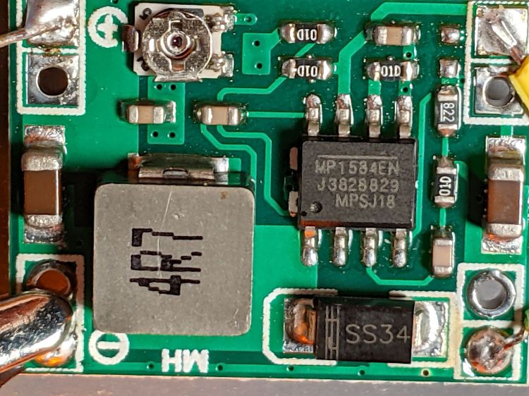
The 01D resistors use the EIA-96 identifier series and are 100 kΩ.
Based on simpleminded testing, a 1 W amber LED drops about 2.5 V at 430 mA. A 1 Ω ballast resistor drops another half volt and burns a quarter of a watt, sufficient to cover some LED forward drop variation.
The trimpot is entirely too twitchy, so I replaced it with an SMD resistor:

The trimpot read 26.5 kΩ after I extracted it, but I surely nudged it a smidgen in the process.
For the record (first column is SMD topmark, second is measured resistance):
- 3012 = 29.9 kΩ (!!) → 3.67 V into a 100 Ω resistor
- 2492 = 24.9 kΩ → 3.19 V : 2.63 V @ 550 mA = 1.45 W
- 2362 = 22.6 kΩ → 2.97 V : 2.52 V @ 450 mA = 1.13 W
- 223 = 22.0 kΩ → 2.91 V : 2.484 V @ 425 mA = 1.06 W
With 6.3 V @ 210 mA = 1.3 W from the bench regulator, the resistor now burns 180 mW at 425 mA and the LED burns 82% of the input power.
Letting it cook overnight settled out with the LED at 2.47 V and 440 mA = 1.09 W, with 6.3 V at 220 mA = 1.4 W from the bench supply. The LED dissipates 78% of the input power and the resistor burns 190 mW = 14%, so the regulator uses 120 mW = 8%.
I can come close to the final output voltage by plugging the new resistor value and the 8.2 kΩ resistor (on the PCB) into the MP1584 datasheet equations, but figuring the resistor to get a specific output voltage seems largely empirical.

Comments
2 responses to “Amber 1 Watt LED: MP1584 Hackery”
[…] PCB is the generic MP1584 buck regulator, as seen before in its normal voltage feedback mode, rewired to get feedback based on the LED current, so that it adjusts the output voltage to […]
[…] general idea: a cylindrical holder / heatsink for a 1 W LED on the end of a tube clamped in a Tour Easy fairing mount, much like a […]