Ed Nisley's Blog: Shop notes, electronics, firmware, machinery, 3D printing, laser cuttery, and curiosities. Contents: 100% human thinking, 0% AI slop.
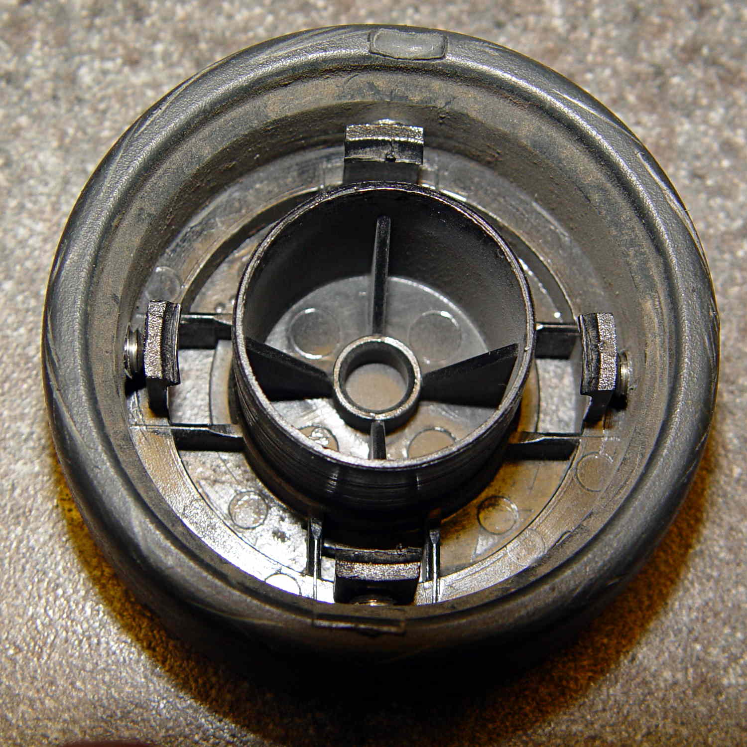
We still haven’t exhausted the never-sufficiently-to-be-damned Samsung Quiet Jet vacuum’s bag supply, so when a wheel fell off the floor brush again, I had to come up with a better fix than a twist of wire. Obviously, those delicate little retaining latches need more persuasion.
Capture the wheel in the Sherline’s 4-jaw chuck on the rotary table and drill four holes just below the end of the latches:
Samsung wheel – drilling
The wheel is 20 mm thick. The holes lie 9 mm back from the open end of the wheel or 11 mm from the closed end at the chuck face. Drill maybe 6 mm down; I did it by eye, jogging slowly downward until the tip of the drill touched the latch.
Tap the holes and install four 8-32 setscrews:
Samsung wheel – setscrews installed
I don’t have a bottoming tap, but an ordinary plug tap was Good Enough; the incomplete threads should hold the setscrews in place.
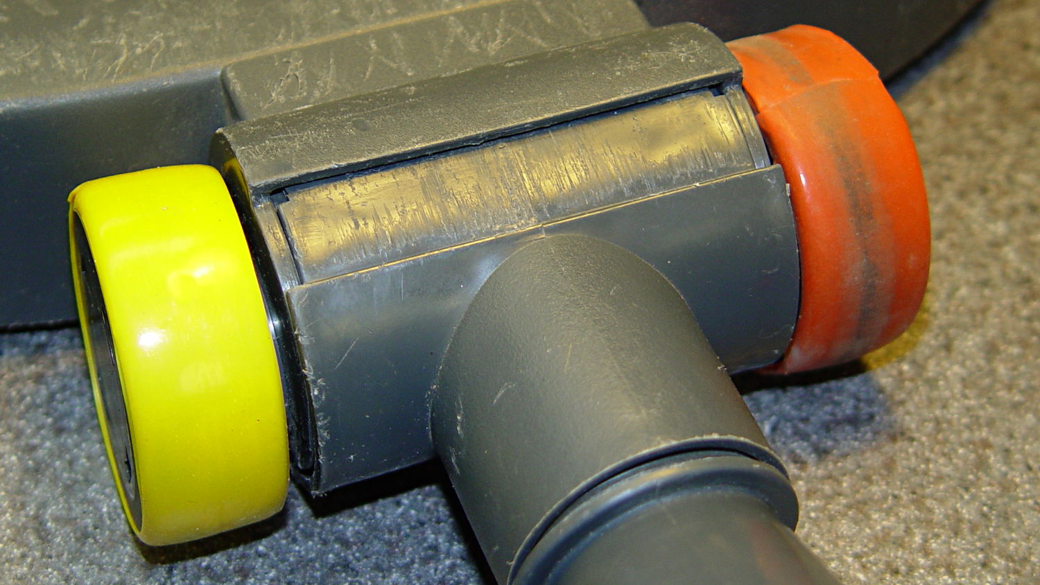
Reinstall the wheel, tighten the setscrews, and wrap festive silicone tape around the whole affair:
Samsung floor brush – wheel installed
I heroically resisted the temptation to pry the other wheel off for a preemptive repair …
Quite a while ago, I rebuilt a gooseneck shop lamp with an LED floodlight module, the light from which appears in many pictures of the Sherline mill. That module has a sibling that I just combined with a defunct halogen desk lamp to produce a better task light for the bench; the original 12 VAC 50 W transformer now loafs along at 4 W and ballasts the lamp base against tipping.
My initial idea, of course, was a 3D printed adapter from the existing arm hardware to the LED module, but PLA gets droopy at normal high-intensity LED heatsink temperatures. That led to doodling a metal bracket around the LED module flange, which led to pondering how annoying that would be to make, which led to the discovery that the screws holding the LED plug to the heatsink were ordinary M2x0.4 Philips head, which suggested I could just screw a bracket to the back of the module, which brought a recently harvested aluminum heatsink to hand, which led to the discovery that the tip of the pivot screw fit perfectly between the fins, which …
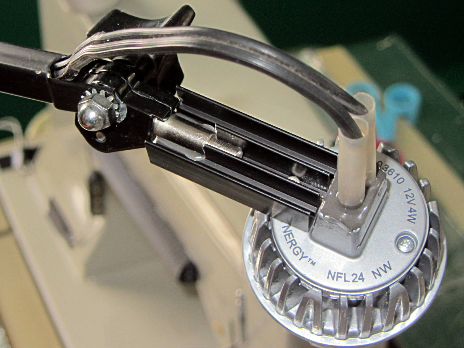
Shortly thereafter, I milled off the central fins to fit the shaft of the pivot screw, introduced the heatsink to Mr. Disk Sander to bevel the bottom, sawed the threads off the pivot, press-fit the two together, drilled a 2 mm cross-hole into the pivot, buttered it all up with epoxy, jammed a short M2 screw into the cross hole, and let the whole mess cure:
Desk Lamp LED Adapter – top view
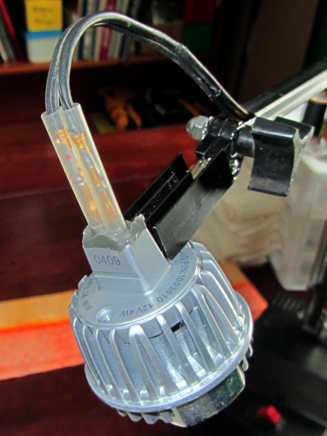
The lamp modules were a surplus find, with one pin clipped nearly flush to the insulator. I soldered a pair of the same male pins as in the battery holders, with the matching female pins as a crude connector. The unshrunk heatstink tubing isn’t lovely, but got us to First Light:
Desk Lamp LED Adapter – front view
The original counterweight is, of course, much too heavy for the dinky LED module, so I’ll drill the mounting hole for the vertical arm further back on the beam to get another foot of reach. That will require more wire between the transformer to the lamp, soooo the connectors might just become soldered joints.
As you can tell from the background, Mary snatched the lamp from my hands and put it to immediate use in The Quilting Room.
The original doodles bear no resemblance to the final product, but do have some key dimensions that (having discarded the unused hardware) I’ll likely never need again.
The pivot between the arm and the lamp housing, with an idea for the LED holder:
Desk Lamp Bracket Dimensions – doodle
Details of the repurposed heatsink and the pivot bolt, with a block that never got built:
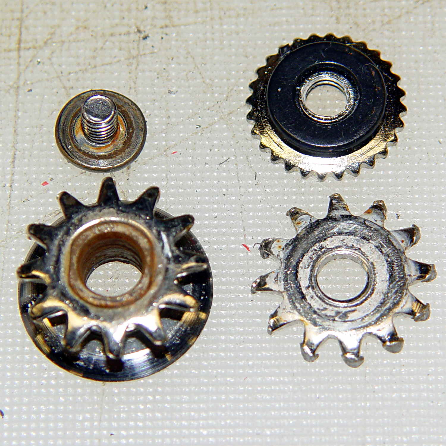
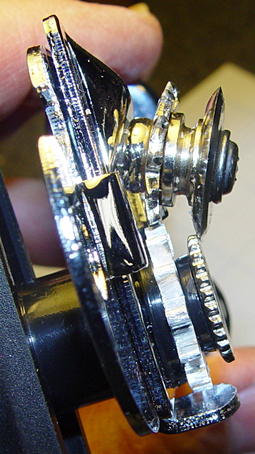
Cleaning up the wrecked gears on the can opener made it painfully obvious that I had to conjure at least one gear to get the poor thing working again:
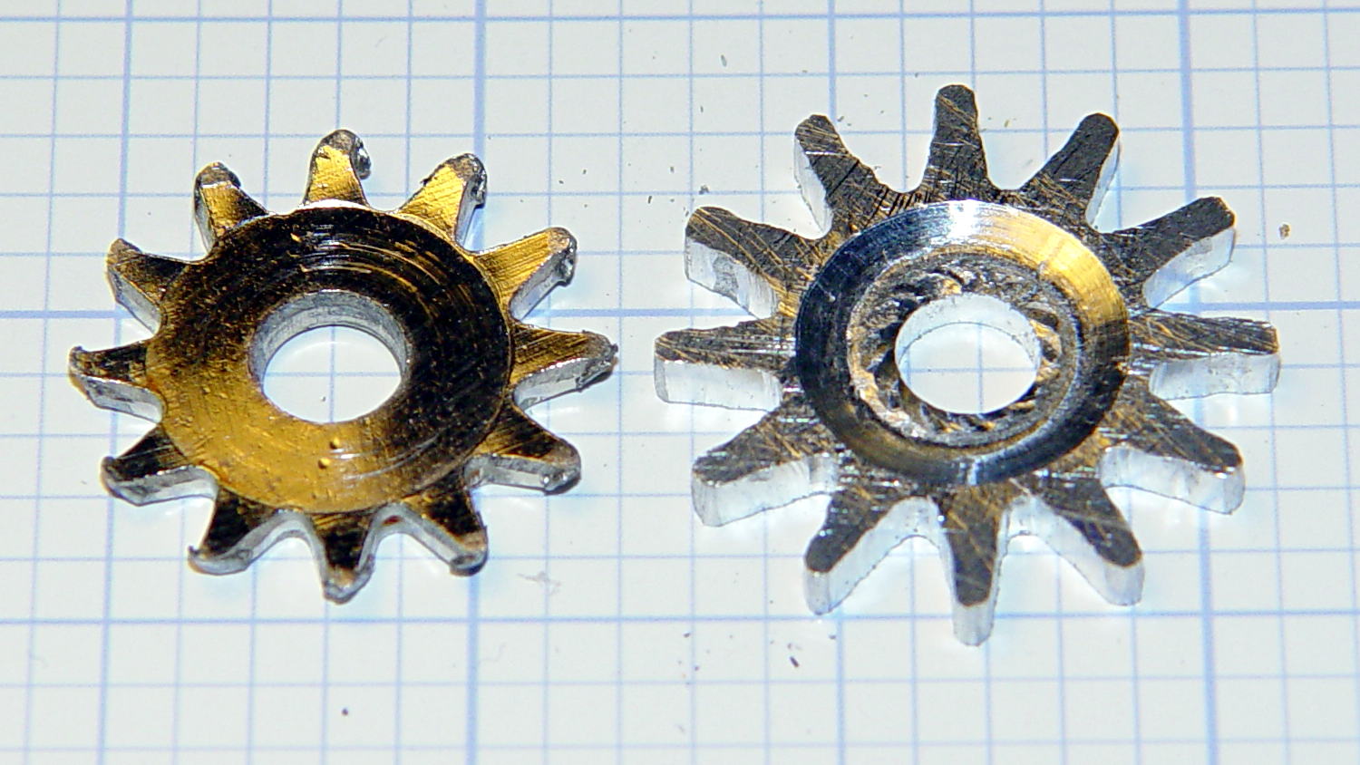
Can opener – gears and cutters
Fortunately, those are more in the line of cogs, rather than real gears, so I decided a crude hack would suffice: drill a pattern of holes to define the openings between the teeth, file / grind the teeth reasonably smooth, and then tweak the shape to suit.
Fitting some small number-size drills between the remains of the teeth showed:
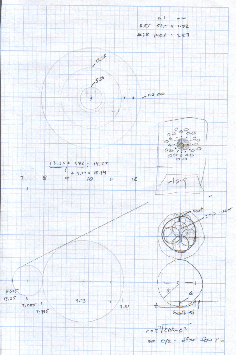
A #52 = 52.0 mil = 1.32 mm drill matched the root curvature
A #28 = 140.5 mil = 3.57 mm drill was tangent to the small drill and the tooth walls
Neither of those count as precision measurements, particularly given the ruined teeth, but they’re close enough for a first pass.
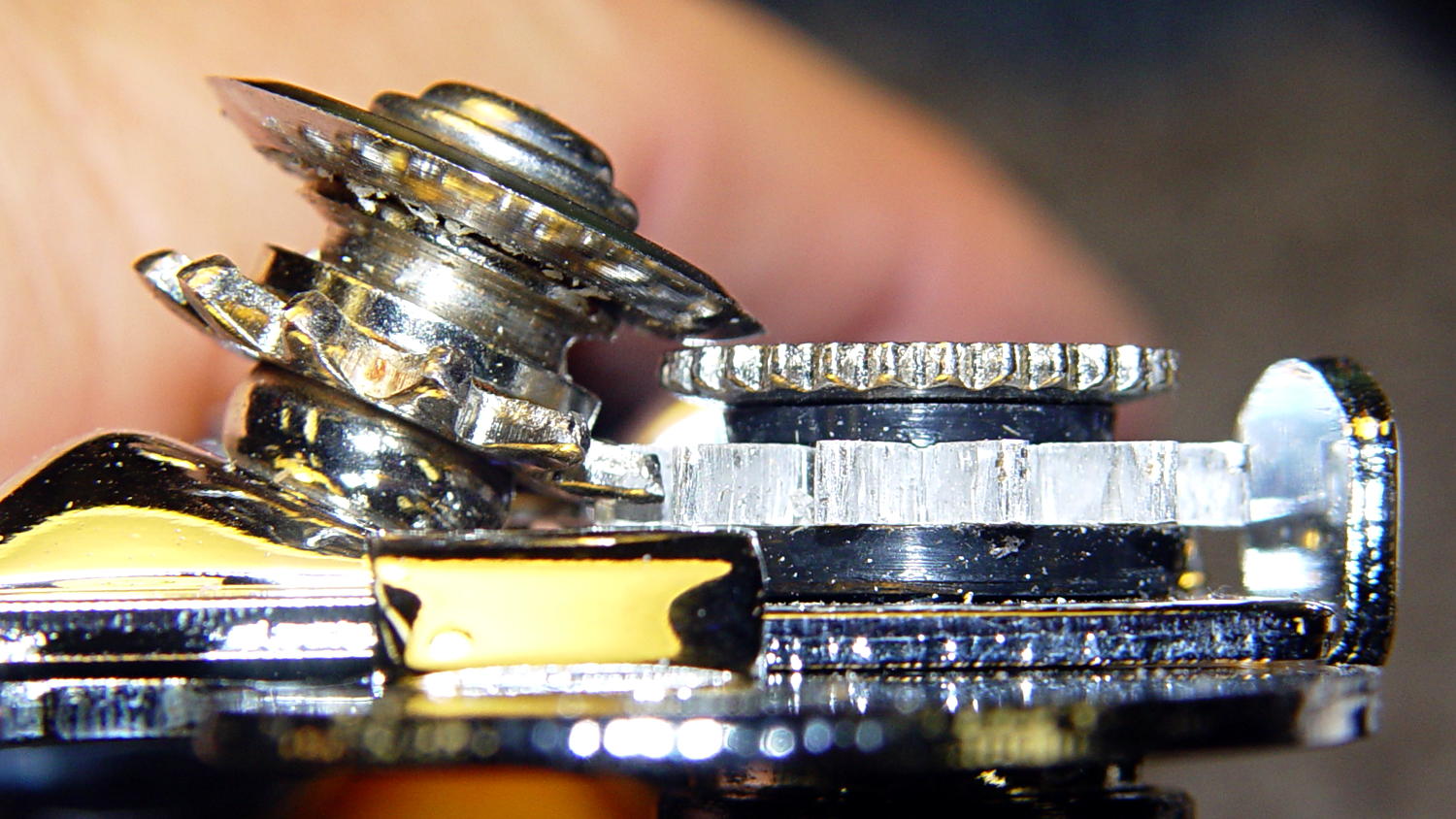
The OEM drive gear (on the right) has the teeth bent upward to mate with the cutter gear (on the left), but under normal gripping force, the teeth don’t mesh securely and tend to slide over / under / past each other. However, if I were to cut the drive gear from a metal sheet that’s thick enough to engage both the root and the crest of the cutter gear, that should prevent all the slipping & sliding. Some eyeballometric guesstimation suggested 2.5 mm would be about right and the Basement Laboratory Stockpile produced a small slab of 100 mil = 2.54 mm aluminum sheet.
However, the center part of the gear must have the same thickness as the OEM gear to keep the drive wheel at the same position relative to the cutter blade, which means a bit of pocket milling. I have some small ball burrs that seemed like they might come in handy.
A recent thread on the LinuxCNC mailing list announced Bertho Stultien’s gcmc, the G-Code Meta Compiler, and this looked like a golden opportunity to try it out. Basically, gcmc lets you write G-Code programs in a C-like language that eliminates nearly all the horrendous syntactic noise of raw G-Code. I like it a lot and you’ll be seeing more of it around here…
The gcmc source code, down below, include a function that handles automatic tool height probing, using that simple white-goods switch. The literal() function emits whatever you hand it as text for the G-Code file, which is how you mechanize esoteric commands that gcmc doesn’t include in its repertoire. It’s basically the same as my bare G-Code probe routine, but now maintains a state variable that eliminates the need for separate first-probe and subsequent-probe entry points.
One point that tripped me up, even though I should know better: because gcmc is a compiler, it can’t read G-Code parameters that exist only when LinuxCNC (or whatever) is interpreting the G-Code. You can write parameters with values computed at compile time, but you can’t read and process them in the gcmc program.
Anyhow, the first pass produced an array of holes that, as I fully expected, weren’t quite right:
Can opener gear – first hole pattern
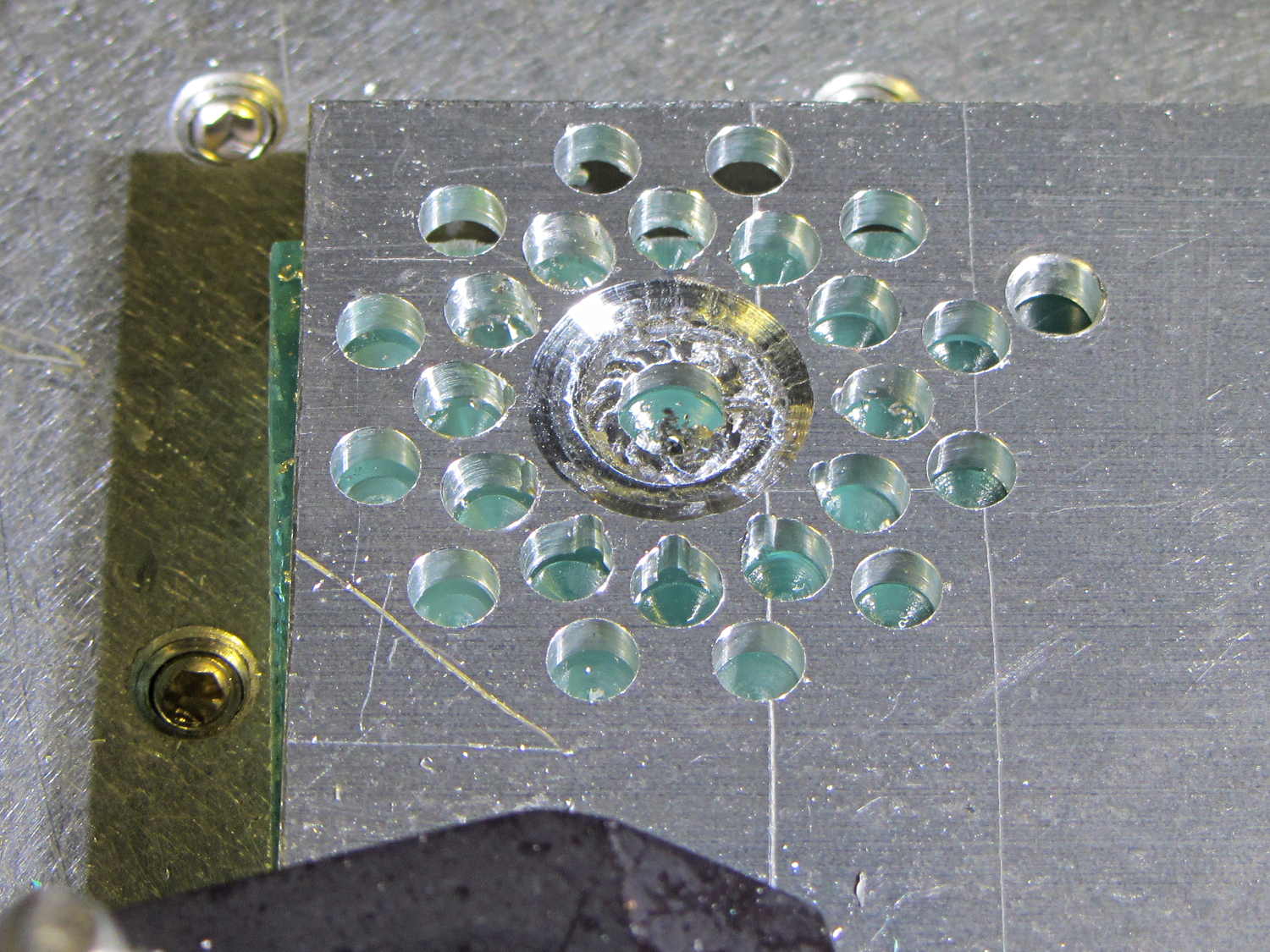
The second pass got the root and middle holes tangent to each other:
Can opener gear – second hole pattern
It also ran a center drill pass for those tiny little holes to prevent their drill from wandering about. The other drills are about the same size as the center drill, so they’re on their own.
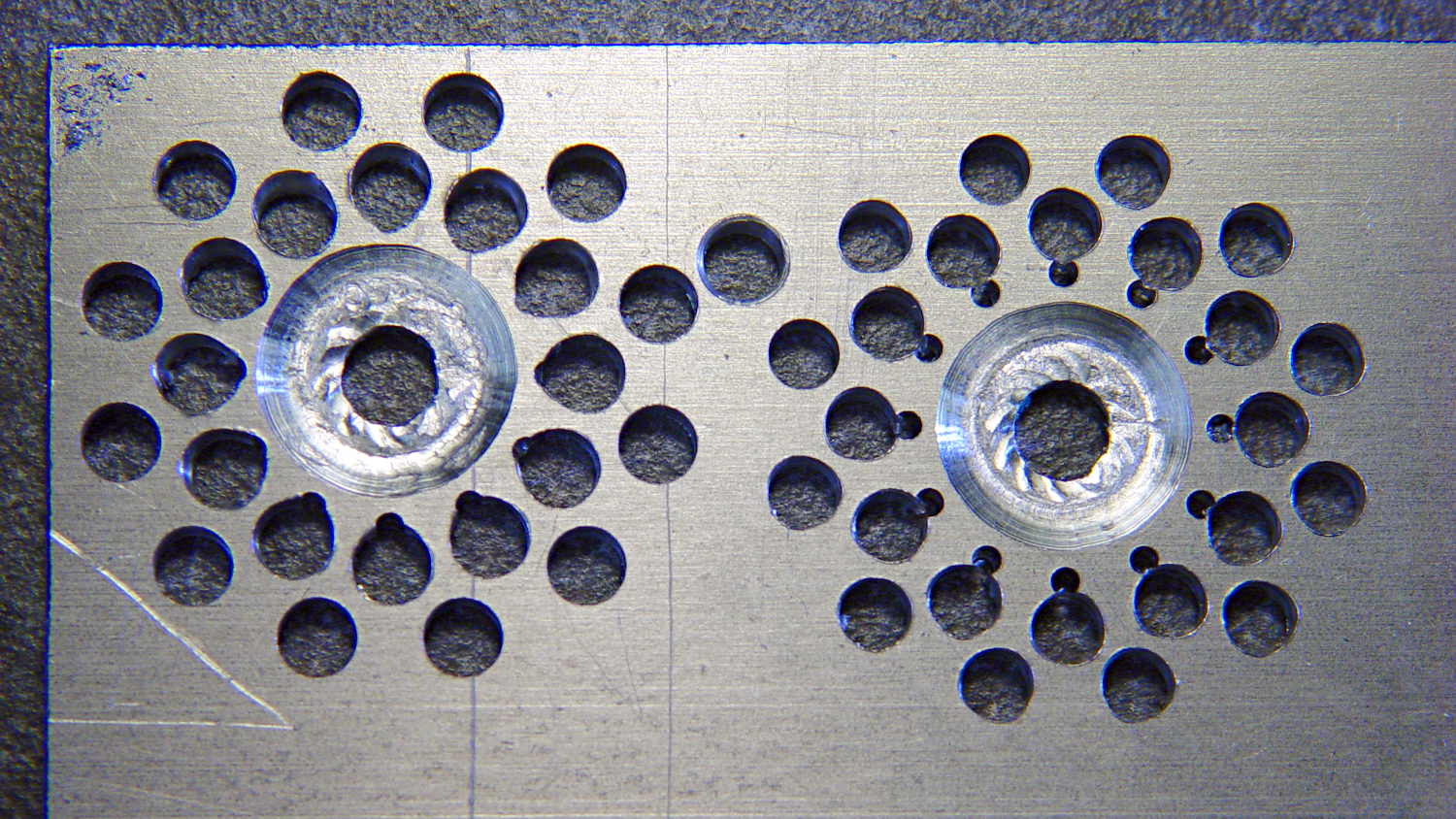
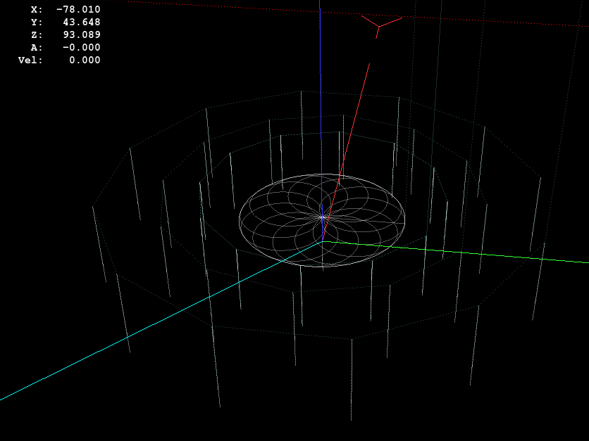
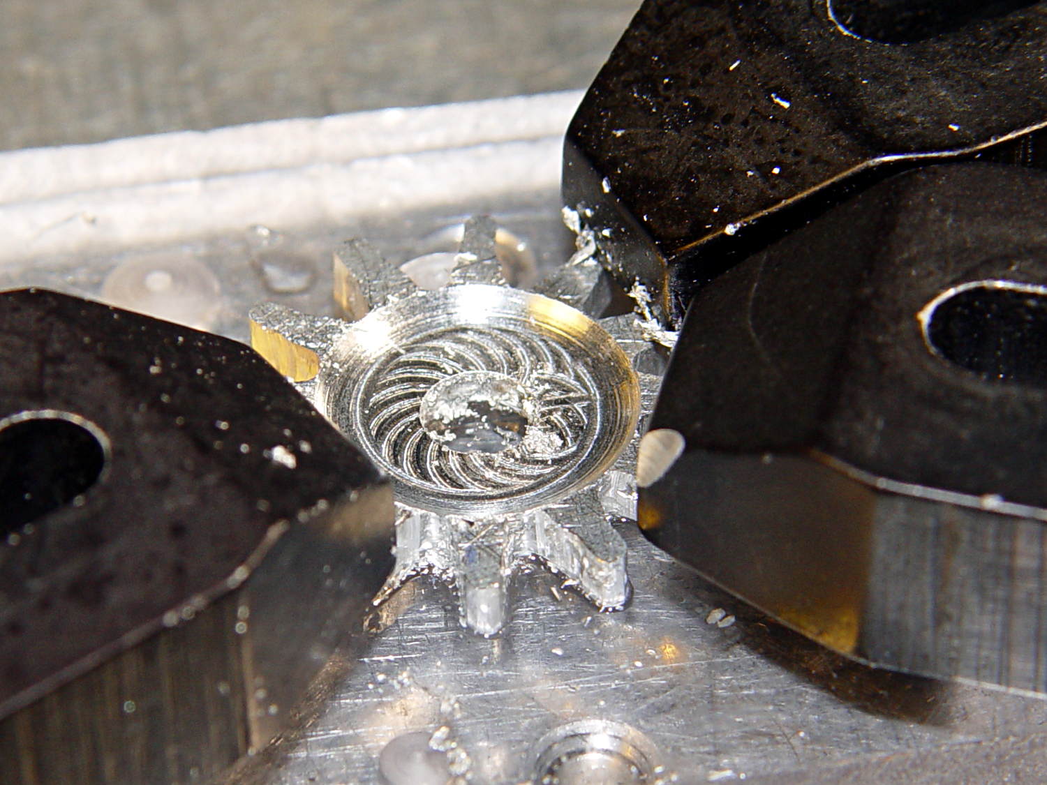
The rosette around the central hole comes from sweeping the burr in a dozen overlapping circles tangent to the outer diameter, then making a cleanup pass around the OD:
Can opener gear – 12 leaf rosette
Incidentally, that stray hole between the two patterns came from the aluminum sheet’s previous life, whatever it may have been. There are three other holes, two of which had flat washers taped to them, so your guess is as good as mine. That’s my story and I’m sticking with it.
Introducing the sheet to Mr Bandsaw and cutting through the outer ring produced a bizarre snowflake:
Can opener gear – cut out
Cutting off the outer ring of holes turned the incipient gear body into a ragged shuriken:
Can opener gear – isolated
A few minutes of increasingly deft Dremel cutoff wheel work, poised on the bench vise over the shopvac nozzle to capture the dust, produced a credible gear shape:
Can opener gear – first pass
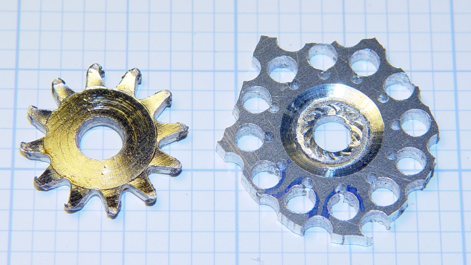
Iterating through some trial fits, re-grinds, and general fiddling showed that the center pocket was too shallow. The cutter wheel should slightly clear the drive wheel, but it’s an interference fit:
Can opener gear – trial fit
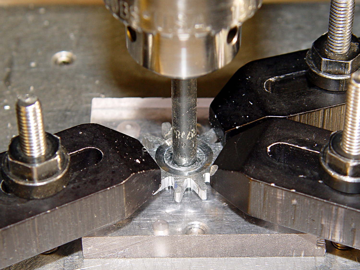
Which, of course, meant that I had to clamp the [mumble] thing back in the Sherline and re-mill the pocket. The trick is to impale it on the wrong end of a suitable drill, clamp it down, and touch off that spot as the origin:
Can opener gear – re-centering
I took the opportunity to switch to a smaller ball and make 16 little circles to clear the pocket:
Can Opener Gear – 16 leaf rosette
Now that’s better:
Can opener gear – deeper pocket
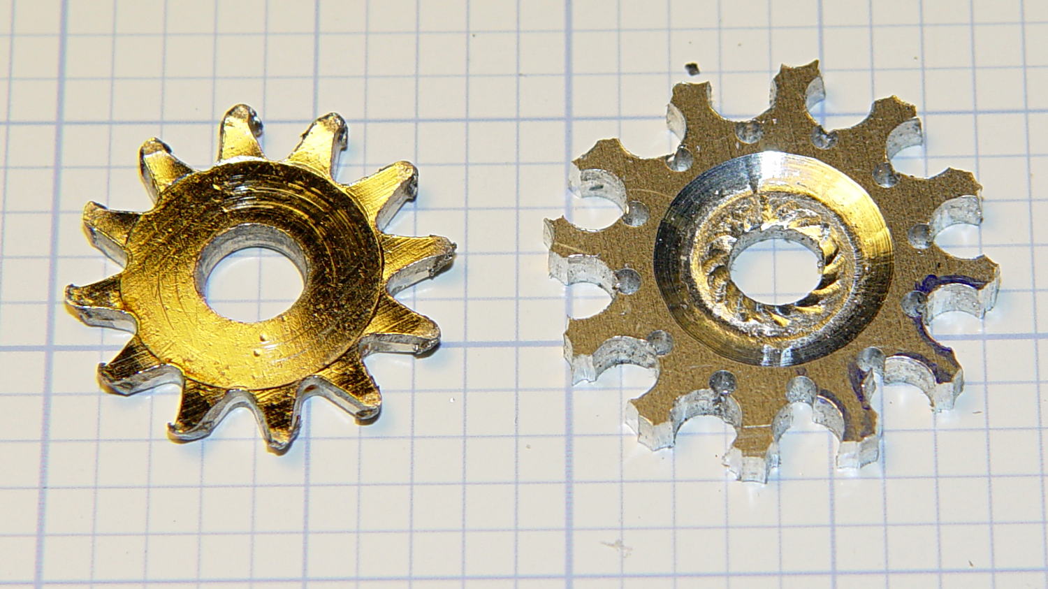
Another trial fit showed that everything ended up in the right place:
Can opener gear – final fit
I gave it a few cranks, touched up any cogs that clashed with the (still misshapen) cutter gear, applied it to a randomly chosen can, and it worked perfectly:
Squeeze the levers to easily punch through the lid
Crankety crank on the handle, while experiencing none of the previous drama
The severed lid falls into the can
Which is exactly how it’s supposed to work. What’s so hard about that?
What you can’t see in that picture is the crest of the lowest cutter gear tooth fitting just above the bottom of the drive gear root. Similarly, the crest of the highest drive gear tooth remains slightly above the cutter root. That means the cutter gear teeth always engage the drive gear, there’s no slipping & sliding, and it’s all good.
Aluminum isn’t the right material for a gear-like object meshed with a steel counterpart, but it’s easy to machine on a Sherline. I’ll run off a few more for show-n-tell and, if when this one fails, I’ll have backup.
The gcmc source code:
// Can opener drive gears
//	Ed Nisley KE4ZNU - February 2014
//	Sherline CNC mill with tool height probe
//	XYZ touchoff origin at center on fixture surface

DO_DRILLCENTER	= 1;
DO_MILLCENTER	= 1;
DO_DRILLINNER	= 1;
DO_DRILLOUTER	= 1;
DO_DRILLTIPS	= 1;

//----------
// Overall dimensions

GearThick = 2.54;			// overall gear thickness
GearCenterThick = 1.75;		// thickness of gear center

GearTeeth = 12;				// number of teeth!
ToothAngle = 360deg/GearTeeth;
GearOD = 22.0;				// tooth tip
GearID = 13.25;				// tooth root

SafeZ = 20.0;				// guaranteed to clear clamps
TravelZ = GearThick + 1.0;	// guaranteed to clear plate

//----------
// Tool height probe
//	Sets G43.1 tool offset in G-Code, so our Z=0 coordinate always indicates the touchoff position

ProbeInit = 0;					// 0 = not initialized, 1 = initialized
ProbeSpeed = 400.0mm;
ProbeRetract = 1.0mm;

PROBE_STAY = 0;					// remain at probe station
PROBE_RESTORE = 1;				// return to previous location after probe

function ProbeTool(RestorePos) {

local WhereWasI;

	WhereWasI = position();

	if (ProbeInit == 0) {		// probe with existing tool to set Z=0 as touched off
		ProbeInit++;
		literal("#<_Probe_Speed> = ",to_none(ProbeSpeed),"\n");
		literal("#<_Probe_Retract> = ",to_none(ProbeRetract),"\n");
		literal("#<_ToolRefZ> = 0.0 \t; prepare for first probe\n");
		ProbeTool(PROBE_STAY);
		literal("#<_ToolRefZ> = #5063 \t; save touchoff probe point\n");
		literal("G43.1 Z0.0 \t; set zero offset = initial touchoff\n");
	}
	elif (ProbeInit == 1) {		// probe with new tool, adjust offset accordingly
		literal("G49 \t; clear tool length comp\n");
		literal("G30 \t; move over probe switch\n");
		literal("G59.3 \t; use coord system 9\n");
		literal("G38.2 Z0 F#<_Probe_Speed> \t; trip switch on the way down\n");
		literal("G0 Z[#5063 + #<_Probe_Retract>] \t; back off the switch\n");
		literal("G38.2 Z0 F[#<_Probe_Speed> / 10] \t; trip switch slowly\n");
		literal("#<_ToolZ> = #5063 \t; save new tool length\n");
		literal("G43.1 Z[#<_ToolZ> - #<_ToolRefZ>] \t; set new length\n");
		literal("G54 \t; return to coord system 0\n");
		literal("G30 \t; return to safe level\n");
	}
	else {
		error("*** ProbeTool sees invalid ProbeInit: ",ProbeInit);
		comment("debug,*** ProbeTool sees invalid ProbeInit: ",ProbeInit);
		ProbeInit = 0;
	}

	if (RestorePos == PROBE_RESTORE) {
		goto(WhereWasI);
	}

}

//----------
// Utility functions

function WaitForContinue(MsgStr) {
	comment(MsgStr);
	pause();
}

function CueToolChange(MsgStr) {
	literal("G0 Z" + SafeZ + "\n");
	literal("G30\n");
	WaitForContinue(MsgStr);
}

function ToolChange(Info,Name) {
	CueToolChange("msg,Insert " + to_mm(Info[TOOL_DIA]) + " = " + to_in(Info[TOOL_DIA]) + " " + Name);
	ProbeTool(PROBE_STAY);

	WaitForContinue("msg,Set spindle to " + Info[TOOL_SPEED] + " rpm");
	feedrate(Info[TOOL_FEED]);
}

function GetAir() {
	goto([-,-,SafeZ]);
}

//-- compute drill speeds & feeds based on diameter
//		rule of thumb is 100 x diameter at 3000 rpm for real milling machines
//		my little Sherline's Z axis can't produce enough thrust for that!

MaxZFeed = 600.0mm;				// fastest possible Z feed

TOOL_DIA = 0;					// Indexes into DrillParam() result
TOOL_SPEED = 1;					//  spindle RPM
TOOL_FEED = 2;					//	linear feed
TOOL_TIP = 3;					//	length of 118 degreee drill tip

function DrillParam(Dia) {
local RPM,Feed,Tip,Data,Derating;

	Derating = 0.25;			// derate from (100 x diameter) max feed

	RPM = 3000.0;				// default 3 k rpm

	Feed = Derating * (100.0 * Dia);
	if (Feed > MaxZFeed) {
		RPM *= (MaxZFeed / Feed);	//  scale speed downward to fit
		Feed = MaxZFeed;
	}

	Tip = (Dia/2) * tan(90deg - 118deg/2);
	Data = [Dia,RPM,Feed,Tip];

	message("DrillParam: ",Data);
	return Data;
}

//-- peck drilling cycle

function PeckDrill(Endpt,Retract,Peck) {
	literal("G83 X",to_none(Endpt[0])," Y",to_none(Endpt[1])," Z",to_none(Endpt[2]),
			" R",to_none(Retract)," Q",to_none(Peck),"\n");
}

//----------
// Make it happen

literal("G99\t;  retract to R level, not previous Z\n");

WaitForContinue("msg,Verify: G30 position in G54 above tool change switch?");

WaitForContinue("msg,Verify: fixture origin XY touched off at center of gear?");

WaitForContinue("msg,Verify: Z touched off on top surface at " + GearThick + "?");
ProbeTool(PROBE_STAY);

//-- Drill center hole

if (DO_DRILLCENTER) {

	DrillData = DrillParam(5.0mm);
	ToolChange(DrillData,"drill");

	goto([0,0,-]);
	goto([-,-,TravelZ]);

	drill([0,0,-1.5*DrillData[TOOL_TIP]],TravelZ,DrillData[TOOL_DIA]);
	GetAir();

}

//-- Drill inner ring

if (DO_DRILLINNER) {

	DrillData = DrillParam(1.32mm);

	RingRadius = GearID/2.0 + DrillData[TOOL_DIA]/2.0;		// center of inner ring holes
	HolePosition = [RingRadius,0mm,-1.5*DrillData[TOOL_TIP]];

//	but first, center-drill to prevent drifting

	CDData = DrillParam(1.00mm);			// pretend it's a little drill
	CDData[TOOL_FEED] = 100mm;				//  ... use faster feed

	CDPosition = HolePosition;				// use center drill coordinates
	CDPosition[2] = GearThick - 0.25mm;		//  ... just below surface

	ToolChange(CDData,"center drill");

	goto([0,0,-]);
	goto([-,-,TravelZ]);

	for (Tooth = 0 ; Tooth < GearTeeth ; Tooth++) {
		drill(CDPosition,TravelZ,2*TravelZ);		// large increment ensures one stroke
		CDPosition = rotate_xy(CDPosition,ToothAngle);
	}

//	now drill the holes

	ToolChange(DrillData,"drill");

	goto([0,0,-]);
	goto([-,-,TravelZ]);

	for (Tooth = 0 ; Tooth < GearTeeth ; Tooth++) {
		PeckDrill(HolePosition,TravelZ,DrillData[TOOL_DIA]);
		HolePosition = rotate_xy(HolePosition,ToothAngle);
	}

	GetAir();

}

//-- Mill center recess

if (DO_MILLCENTER) {

	MillData = [4.50mm,3000,250.0mm,0.0mm];			// spherical ball burr

	Delta = GearThick - GearCenterThick;							// depth to be milled away
	Inset = sqrt(2.0*Delta*(MillData[TOOL_DIA]/2) - pow(Delta,2));	// toll axis to milled edge

	ToolChange(MillData,"ball burr");

	goto([0,0,-]);							// above central hole
	goto([0,0,GearThick]);					// vertically down to flush with surface
	move([0,0,GearCenterThick]);			// into gear blank

	for (Angle = 0.0deg; Angle < 360.0deg; Angle+=360.0deg/16) {	// clear interior
		circle_cw((GearID/2 - Inset)/2,Angle);
	}

	move_r([(GearID/2 - Inset),0.0,0.0]);							// clean rim
	circle_ccw([0.0,0.0,GearCenterThick],2);

	GetAir();

}

//-- Drill outer ring

if (DO_DRILLOUTER) {

	RingRadius += DrillData[TOOL_DIA]/2;		// at OD of inner ring holes

	DrillData = DrillParam(3.18mm);
	RingRadius += DrillData[TOOL_DIA]/2.0;		// center of outer ring holes
	HolePosition = [RingRadius,0mm,-1.5*DrillData[TOOL_TIP]];

	ToolChange(DrillData,"drill");

	for (Tooth = 0 ; Tooth < GearTeeth ; Tooth++) {
		PeckDrill(HolePosition,TravelZ,DrillData[TOOL_DIA]);
		HolePosition = rotate_xy(HolePosition,ToothAngle);
	}

	GetAir();

}

//-- Drill to locate gear tooth tip end

if (DO_DRILLTIPS) {

	DrillData = DrillParam(4.22mm);

	RingRadius = GearOD/2.0 + DrillData[TOOL_DIA]/2.0;		// tangent to gear tooth tip
	HolePosition = [RingRadius,0mm,-1.5*DrillData[TOOL_TIP]];
	HolePosition = rotate_xy(HolePosition,ToothAngle/2);	// align to tooth

	ToolChange(DrillData,"drill");

	for (Tooth = 0 ; Tooth < GearTeeth ; Tooth++) {
		PeckDrill(HolePosition,TravelZ,DrillData[TOOL_DIA]);
		HolePosition = rotate_xy(HolePosition,ToothAngle);
	}

	GetAir();

}

literal("G30\n");
comment("msg,Done!");
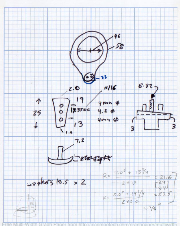
The original doodle that suggested the possibility:
Can Opener Gears – Doodle 1
The chord equation at the bottom shows how to calculate the offset for the ball burr, although it turns out there’s no good way to measure the cutting diameter of the burr and it’s not really spherical anyway.
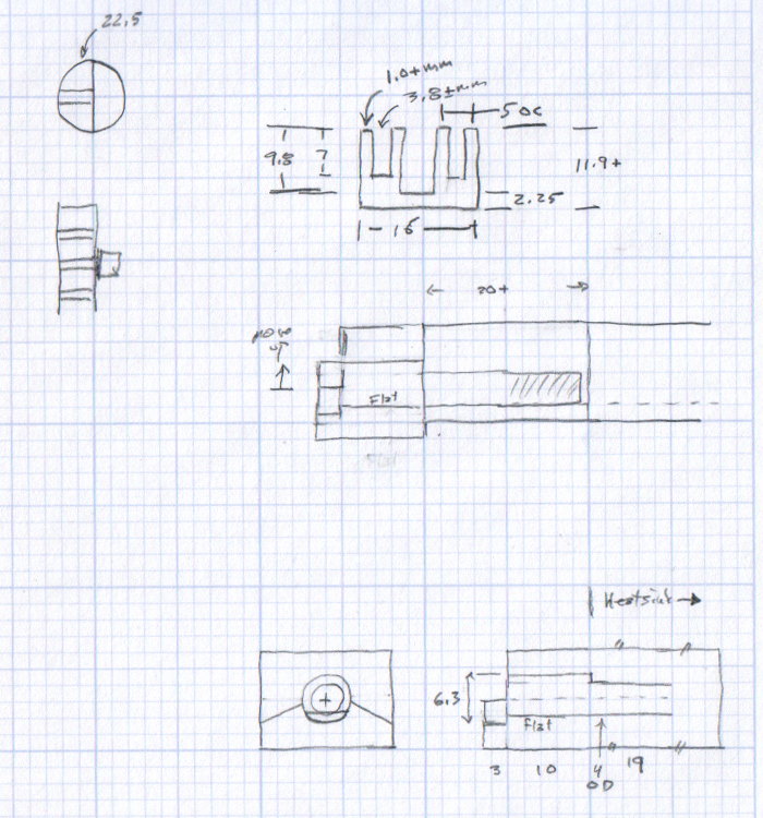
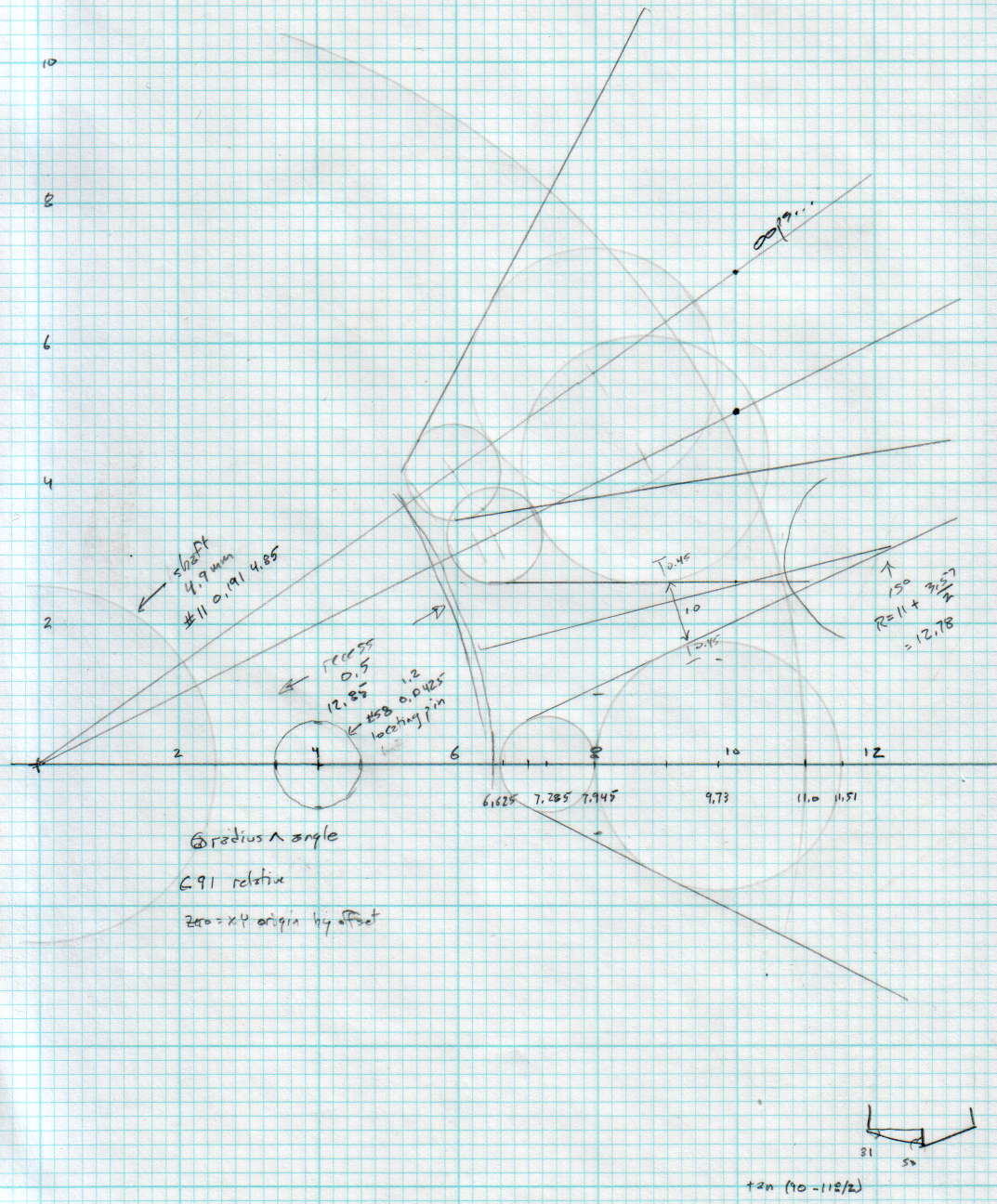
A more detailed doodle with the key line at a totally bogus angle:
Can Opener Gears – Doodle 2
The diagram in the lower right corner shows how you figure the length of the tip on a 118° drill point, which you add to the thickness of the plate in order to get a clean hole.
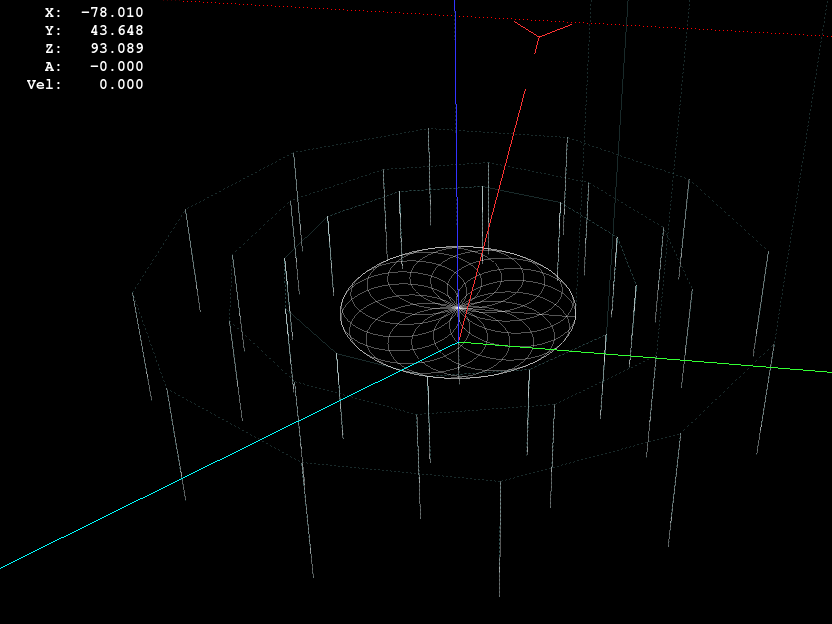
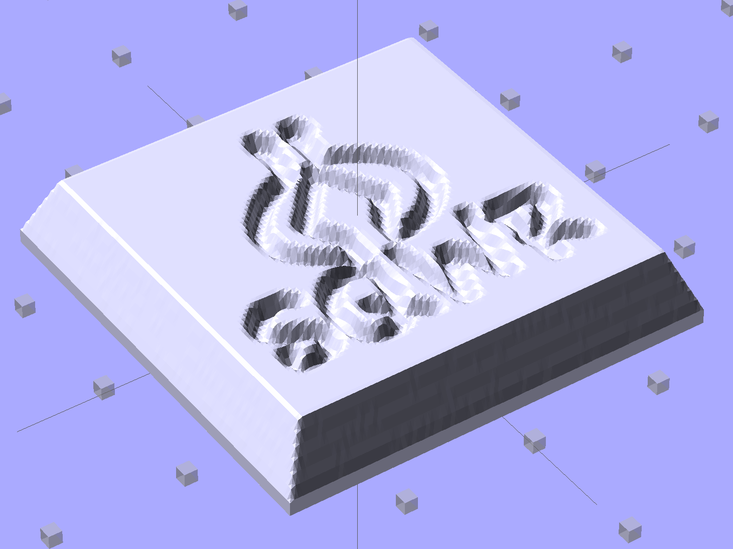
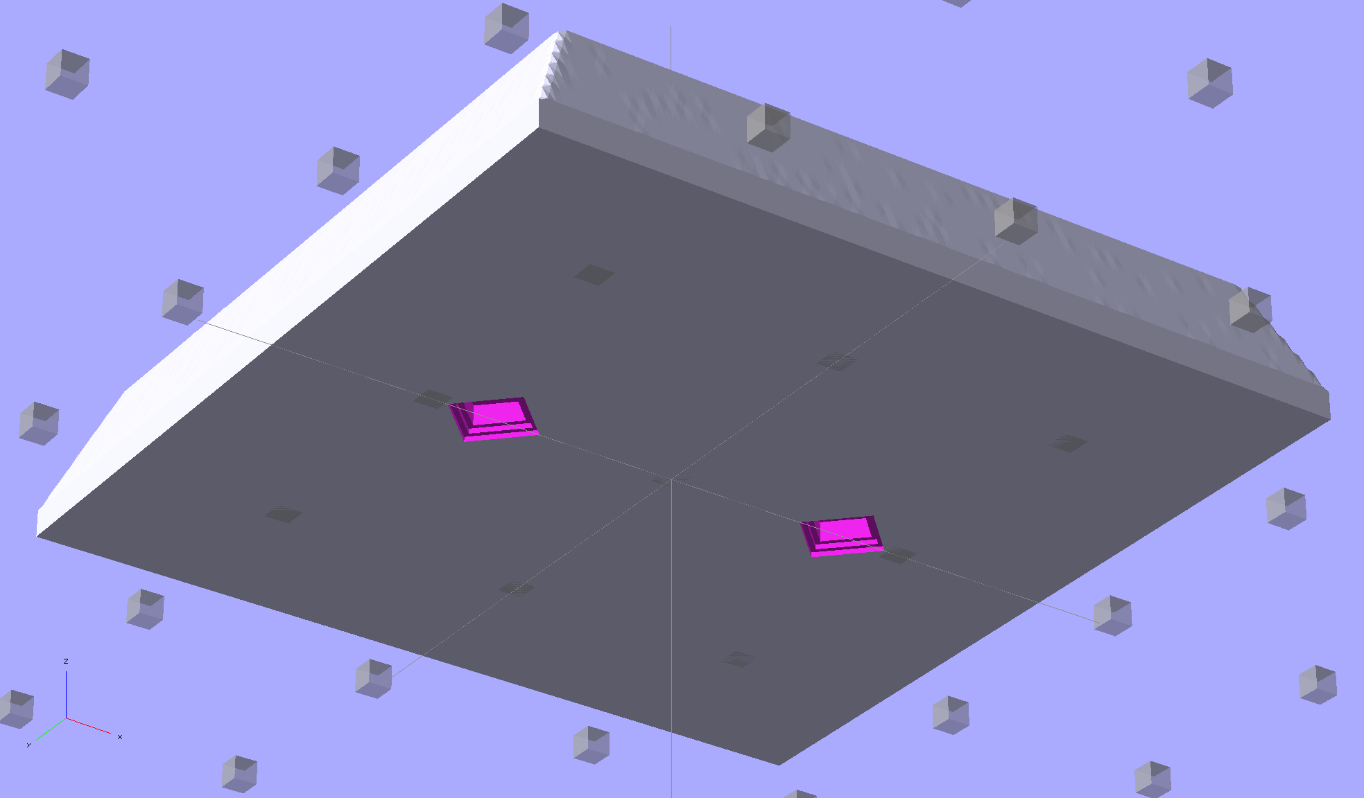
Given an STL file generated from a height map image, import it into OpenSCAD:
SqWr solid model – OpenSCAD – oblique view
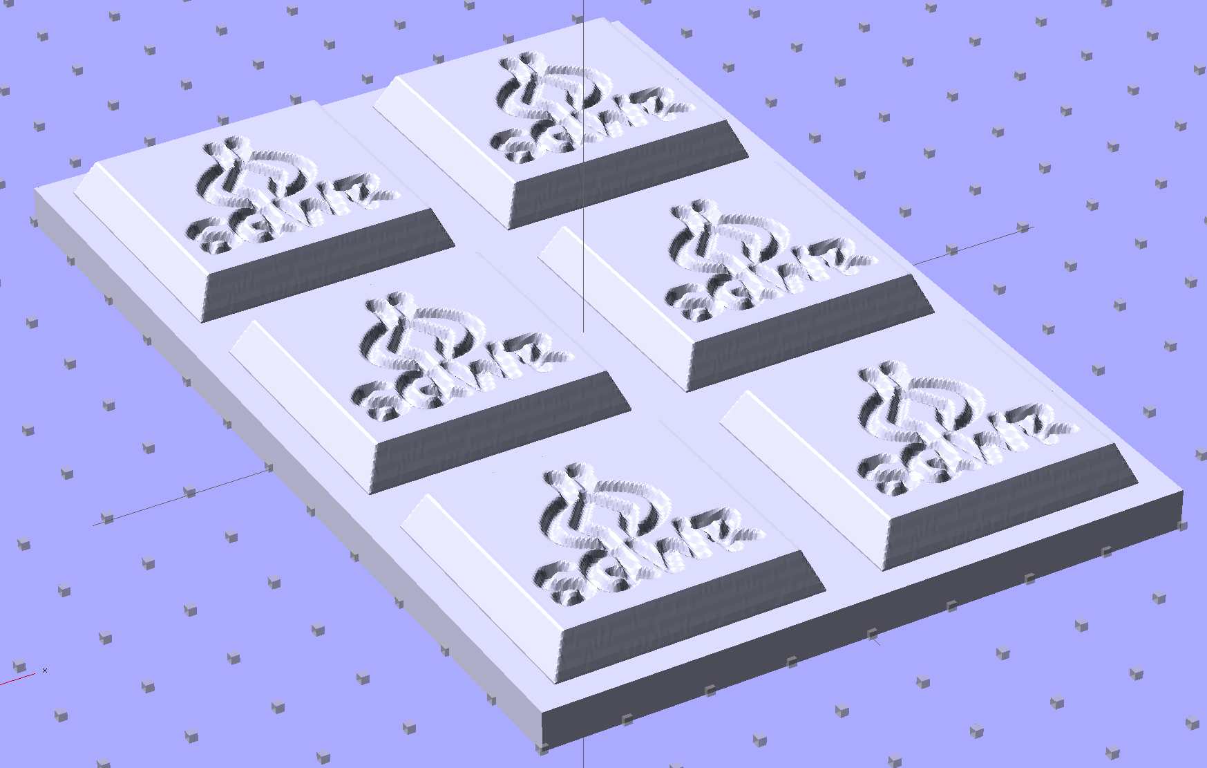
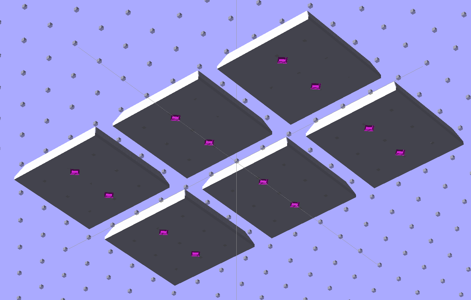
Then slide a plate under six copies to produce a positive model for a casting mold:
SqWr Positive Mold Framework – 2×3
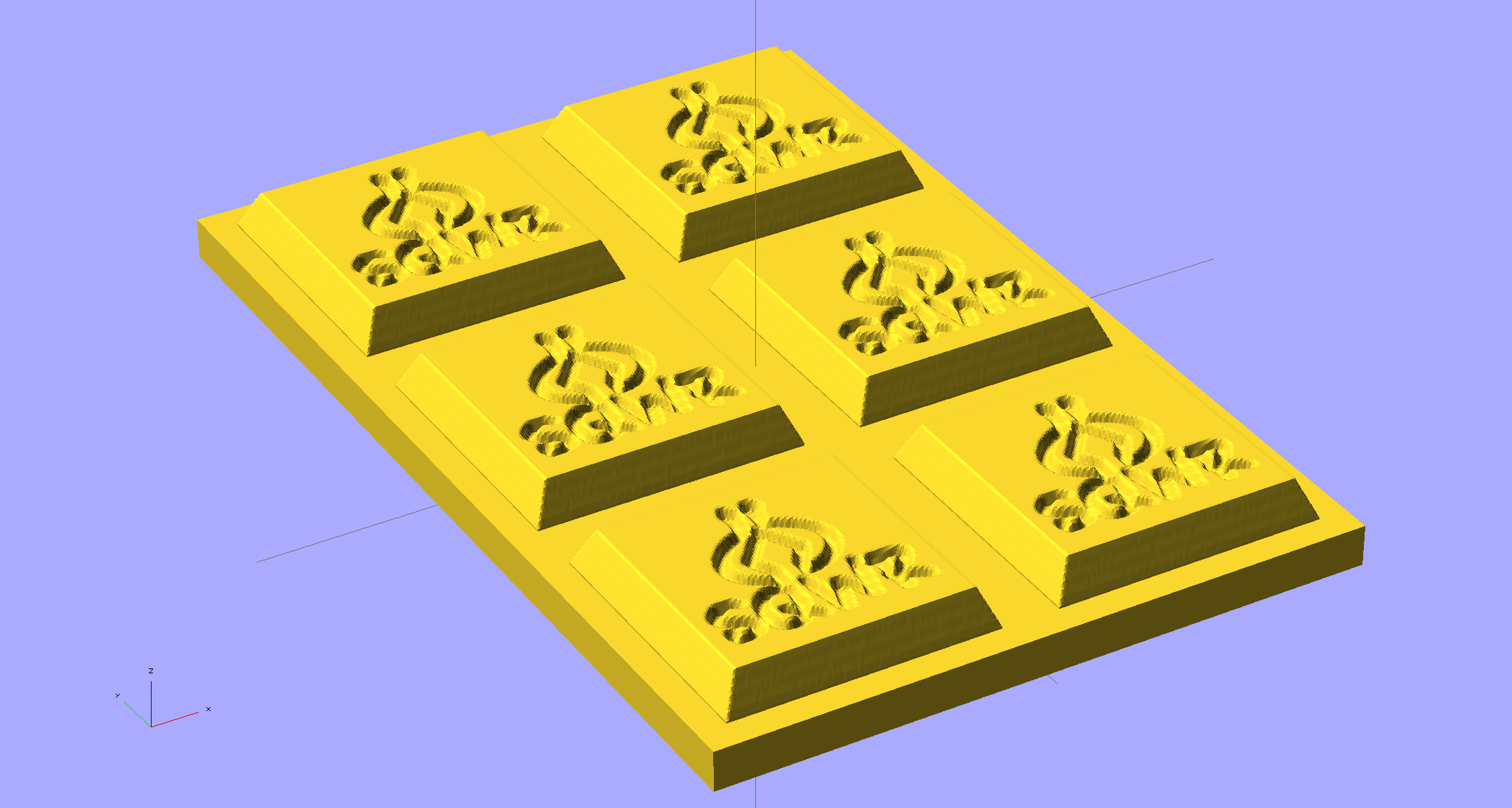
This is one of the few cases where the compiled-and-rendered version looks better, as though you’d shrink-wrapped it in gold foil:
SqWr Positive Mold Framework – 2×3 – gold
The height map STLs each have a bazillion tiny facets that take forever-and-a-day (well, the better part of half an hour for this set) to render, not to mention that the whole array would take two hours to print… and then be used once or twice to produce the flexy silicone negative mold.
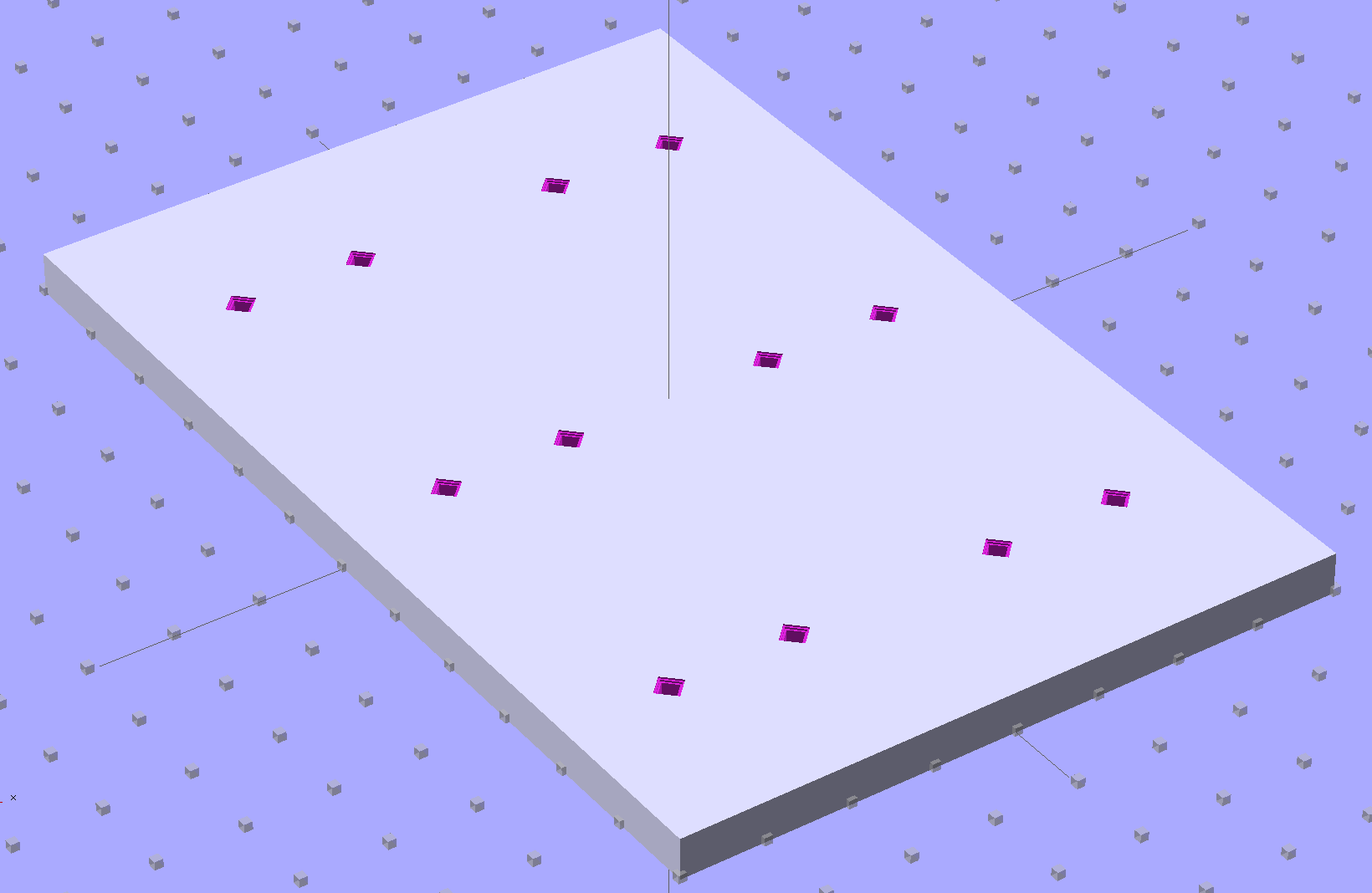
So it’s better to have a generic frame with alignment pin holes that you print once:
SqWr Positive Mold Framework – 2×3 pins
Better yet, just CNC-drill those holes in a nice, flat acrylic / polycarbonate slab.
The OpenSCAD program can punch matching holes in the back of the small mold:
SqWr solid model – OpenSCAD – oblique bottom
Or you could print out an array of the things with holes:
SqWr solid model – 2×3 array – bottom
It’s not clear having OpenSCAD labor for half an hour to generate and emit a single STL file spanning all six molds is a win. Given that you don’t care about the mold-to-mold spacing, having Slic3r duplicate the same small STL file half a dozen (or more!) times would probably be a net win.
There’s no reason the OpenSCAD program that creates the original STL from the height map image can’t punch alignment pin holes, too, which would avoid this import-and-recompile step. If you’re going with a CNC-drilled plate, then it would make even more sense to not have a pair of OpenSCAD programs.
Anyhow.
Apply a handful of small molds to the backing plate with tapeless sticky, butter it up with mold release agent, slather on silicone putty, flip it over to produce a smooth surface “under” the small molds (so you can rest it flat on a table when pouring molten chocolate into the cavities), cure, peel, and you’d get a pretty good negative mold.
This may not make any practical sense, but it was easy & fun to see what’s possible…
The OpenSCAD source code:
// Positive mold framework for chocolate slabs
// Ed Nisley - KE4ZNU - January 2014

Layout = "FramePins";		// Molds FramePins FrameMolds Frame Single Pin

//- Extrusion parameters must match reality!
//  Print with 2 shells and 3 solid layers

ThreadThick = 0.20;
ThreadWidth = 0.40;

Protrusion = 0.1;			// make holes end cleanly

HoleWindage = 0.2;

//----------------------
// Dimensions

FileName = "SqWr-press.stl";	// overrride with -D

Molds = [2,3];					// count of molds within framework

MoldOC = [40.0,40.0];			// on-center spacing of molds
MoldSlab = 1.0;					// thickness of slab under molds

BaseThick = 5.0;

BaseSize = [(Molds[0]*MoldOC[0] + 0),(Molds[1]*MoldOC[1] + 0),BaseThick];
echo(str("Overall base: ",BaseSize));

PinOD = 1.75;					// locating pin diameter
PinLength = 2.0;				//  ... total length
PinSpace = 15.0;				// spacing within mold item

//----------------------
// Useful routines

//- Put peg grid on build surface

module ShowPegGrid(Space = 10.0,Size = 1.0) {

	RangeX = floor(100 / Space);
	RangeY = floor(125 / Space);

	for (x=[-RangeX:RangeX])
		for (y=[-RangeY:RangeY])
			translate([x*Space,y*Space,Size/2])
			%cube(Size,center=true);

}

module PolyCyl(Dia,Height,ForceSides=0) {			// based on nophead's polyholes

  Sides = (ForceSides != 0) ? ForceSides : (ceil(Dia) + 2);

  FixDia = Dia / cos(180/Sides);

  cylinder(r=(FixDia + HoleWindage)/2,
           h=Height,
	   $fn=Sides);
}

// Locating pin hole with glue recess
//  Default length is two pin diameters on each side of the split

module LocatingPin(Dia=PinOD,Len=0.0) {

	PinLen = (Len != 0.0) ? Len : (4*Dia);

	translate([0,0,-ThreadThick])
		PolyCyl((Dia + 2*ThreadWidth),2*ThreadThick,4);

	translate([0,0,-2*ThreadThick])
		PolyCyl((Dia + 1*ThreadWidth),4*ThreadThick,4);

	translate([0,0,-(Len/2 + ThreadThick)])
		PolyCyl(Dia,(Len + 2*ThreadThick),4);

}

module LocatingPins(Length) {
	for (i=[-1,1])
	translate([i*PinSpace/2,0,0])
		LocatingPin(Len=Length);
}

//-- import a single mold item

module MoldItem() {
	import(FileName,convexity=10);
}

//-- Overall frame shape

module Frame() {

	translate([0,0,BaseSize[2]/2])		// platform under molds
		cube(BaseSize,center=true);

}

//- Build it

ShowPegGrid();

if (Layout == "Pin")
	LocatingPin(Len=PinLength);

if (Layout == "Single")
	difference() {
		MoldItem();
		LocatingPins(PinLength);
	}

if (Layout == "Frame")
	Frame();

if (Layout == "Molds") {
	translate([-MoldOC[0]*(Molds[0] - 1)/2,-MoldOC[1]*(Molds[1] - 1)/2,0])
	for (i=[0:Molds[0]-1],j=[0:Molds[1]-1])
		translate([i*MoldOC[0],j*MoldOC[1],0])
			difference() {
				MoldItem();
				LocatingPins(PinLength);
			}
}

if (Layout == "FramePins")
	difference() {
		Frame();

		translate([-MoldOC[0]*(Molds[0] - 1)/2,-MoldOC[1]*(Molds[1] - 1)/2,0])
			for (i=[0:Molds[0]-1],j=[0:Molds[1]-1])
				translate([i*MoldOC[0],j*MoldOC[1],BaseSize[2]])
					LocatingPins(BaseThick);
	}

if (Layout == "FrameMolds") {
	Frame();
	translate([-MoldOC[0]*(Molds[0] - 1)/2,-MoldOC[1]*(Molds[1] - 1)/2,0])
		for (i=[0:Molds[0]-1],j=[0:Molds[1]-1])
			translate([i*MoldOC[0],j*MoldOC[1],BaseThick - MoldSlab + Protrusion])
			MoldItem();
}
For some unknown reason, one of the very rare updates to the Ubuntu 10.04 LTS infrastructure (for LinuxCNC 2.5.3 on my Foxconn D510 box, driving the Sherline mill) stopped supporting the system board’s built-in NIC: networking stopped working. The only symptom was that the NIC didn’t respond and all the usual tricks were unproductive.
After some fruitless searching, I took the easy way out:
NIC added to Foxconn D510 PC
That’s the backside of an ancient NIC using the classic Tulip driver. It used to have a full-size bracket, which I chopped off, bent, and filed to suit, much as with that one in the D525.
Fired it up, the kernel automagically picked the proper driver, and networking Just Worked again.
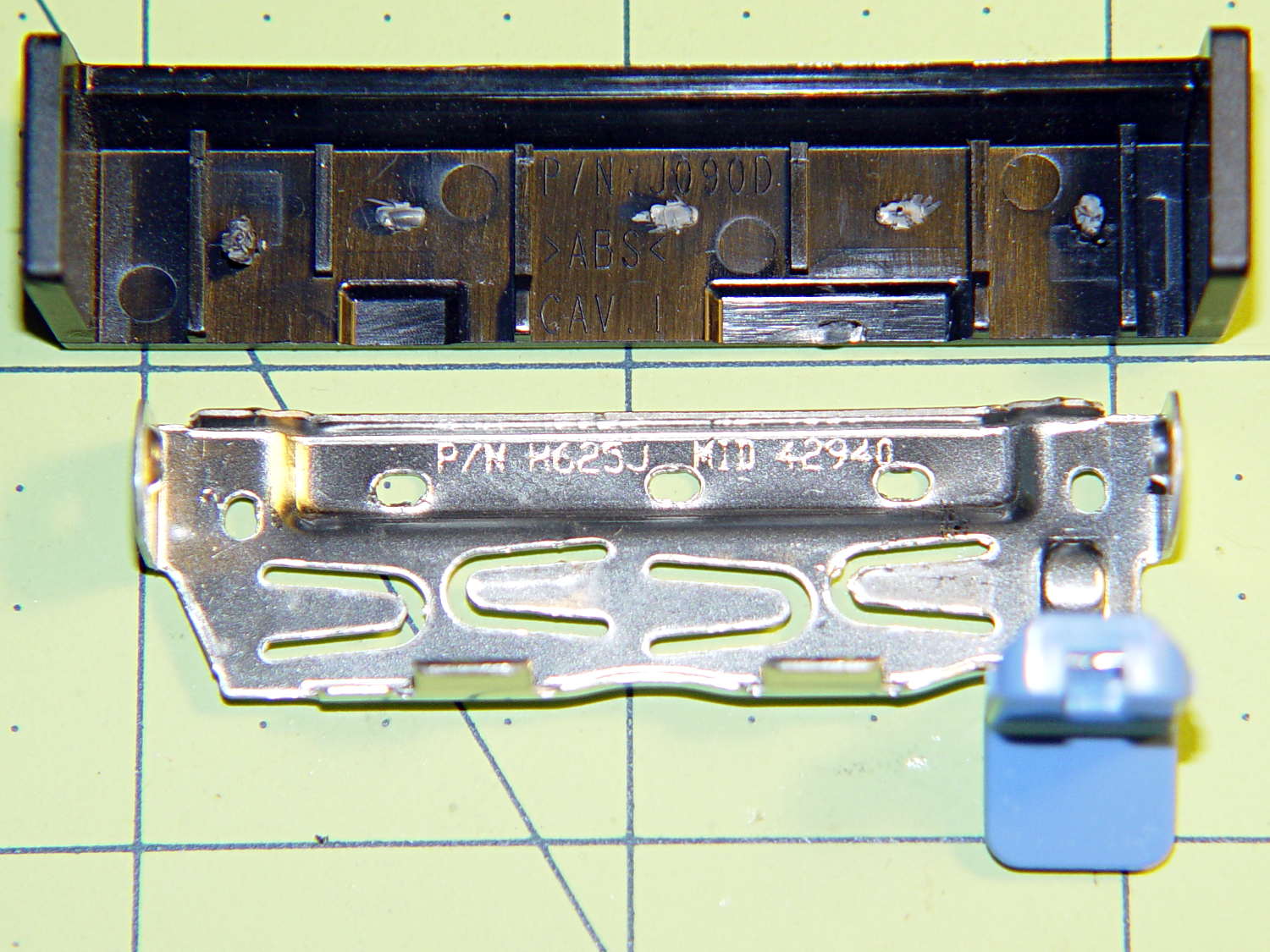
The new-to-me Optiplex 980 has a tool-free clamp securing the PCI card brackets to the chassis, with a nice plastic dress cover that really finishes off that side of the case. Alas, it’s secured by five small heat-staked plastic pegs that I managed to shear off as part of a finger fumble that you’ll recognize when it happens to you and which I need not further discuss:
Optiplex 980 PCI Clamp Cover – disassembled
So I drilled two slightly undersized holes for the tiniest screws in the Little Box o’ Tiny Screws:
Optiplex 980 PCI Clamp Cover – drilling
The two end plates sticking up are the only square parts of the cover, so that thing is actually clamped by the right-side plate and sheer will power. I ran the drill down 3 mm from the top of the post at the slowest manual jog speed from the Joggy Thing and I did not break through the top and did not hit that lathe bit under the cover.
The screw threads and a dab of epoxy hold them in place:
Optiplex 980 PCI Clamp Cover – tiny screws
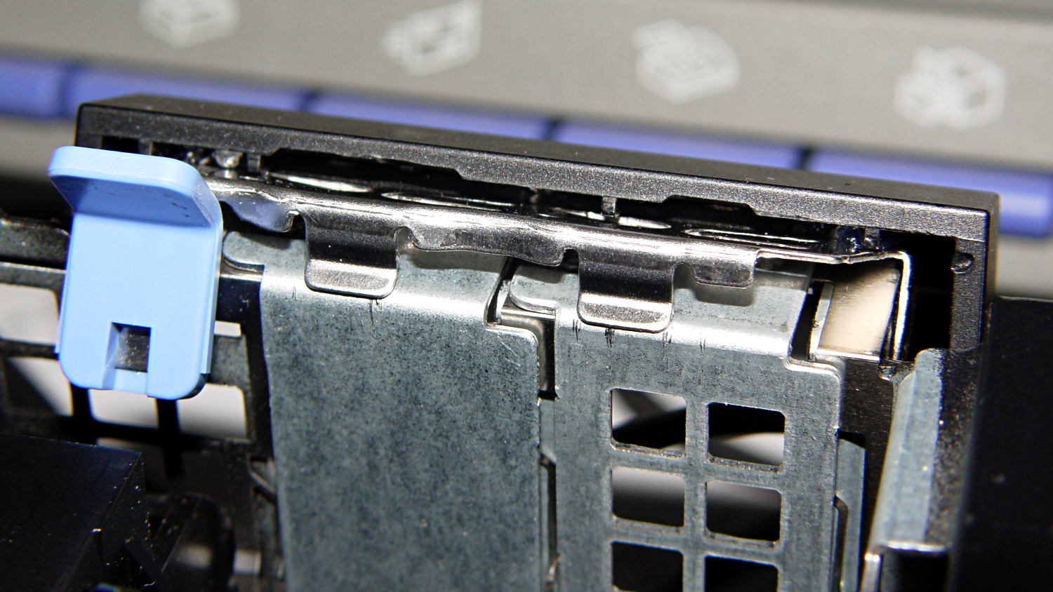
I’d like to say the finished repair looked like this:
Optiplex 980 PCI Clamp Cover – in place
But, alas, the eagle-eyed reader will note that the screws are gone, replaced by two dabs of clear acrylic caulk; those faint threads and epoxy were no match for the snap of that latching lever and the slight distortion caused by the spring fingers applying force to the brackets.
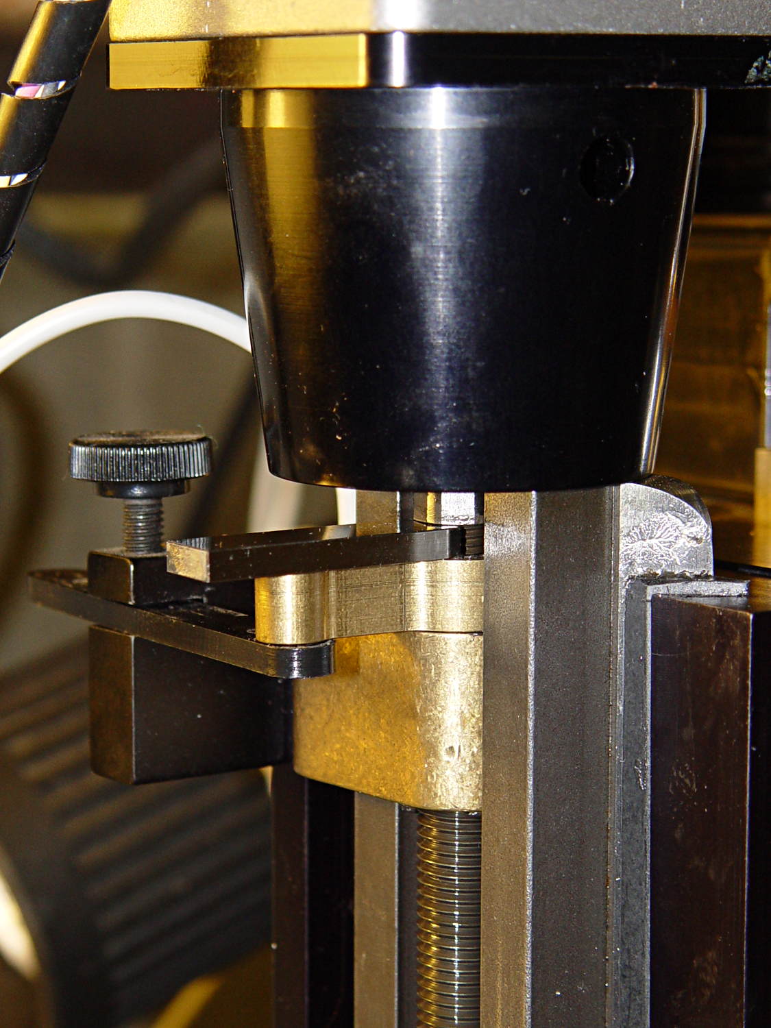
Turns out that it’s 0.1340 inches, determined by bracketing the sliver above that 0.1300 block with feeler gauges. I don’t believe that last zero, either, as the Basement Shop was about 10 °F below the block’s 68 °F calibration temperature. [grin]
The actual size of that gap makes absolutely no difference whatsoever, but fooling around with the gauge blocks gave me an excuse to renew my acquaintance with them and, en passant, massage some oil over their long-neglected bodies:
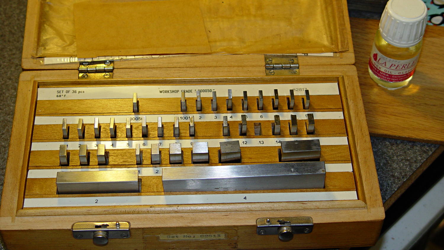
Gauge block set
I used La Perle Clock Oil, which isn’t Official Gauge Block Oil, but doesn’t go bad on the shelf. Verily, this bottle may be the last of its kind, as it’s no longer available from any of the usual sources; it appears I bought it back in 2000.
The blocks are in good shape, probably because they don’t often see the light. FWIW, I have experimentally determined that my body oil doesn’t etch fingerprints into steel.
The block set, which is similar to a current box o’ blocks from Enco, claims “Workshop Grade”, but the ±0.00050 inch = 1.27 μm tolerance shown in the top row of the labels is much worse than even grade B’s sub-micron tolerance. That newer box claims “Economy” accuracy with the same spec, so I suppose somebody kvetched about mis-using the terms.
Ah, well, they’re far better than any measurements I’ve needed in a while and entirely suitable for verifying my other instruments.