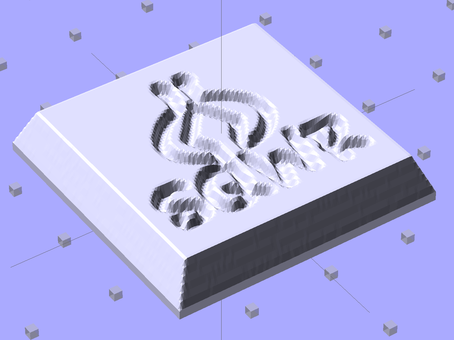
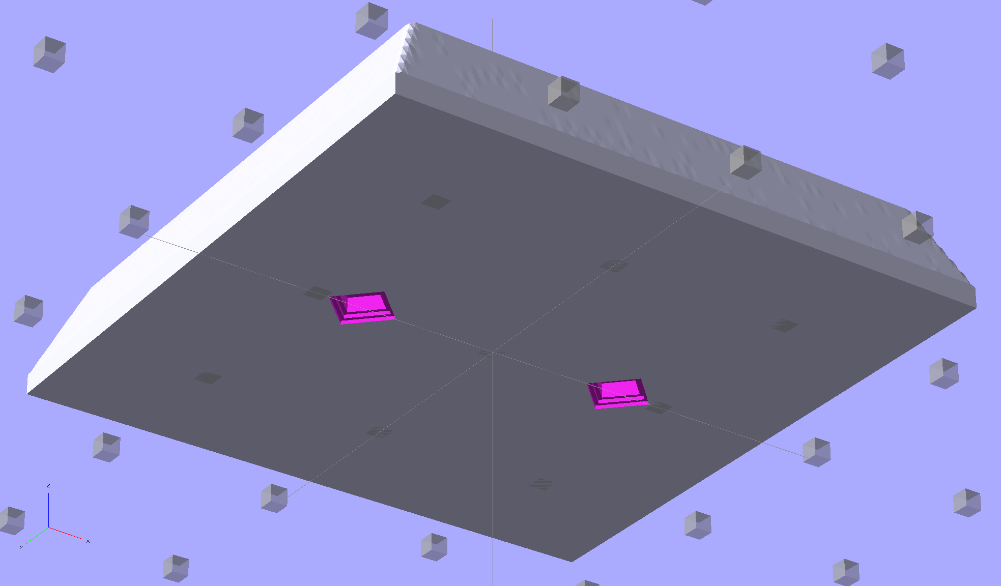
Given an STL file generated from a height map image, import it into OpenSCAD:
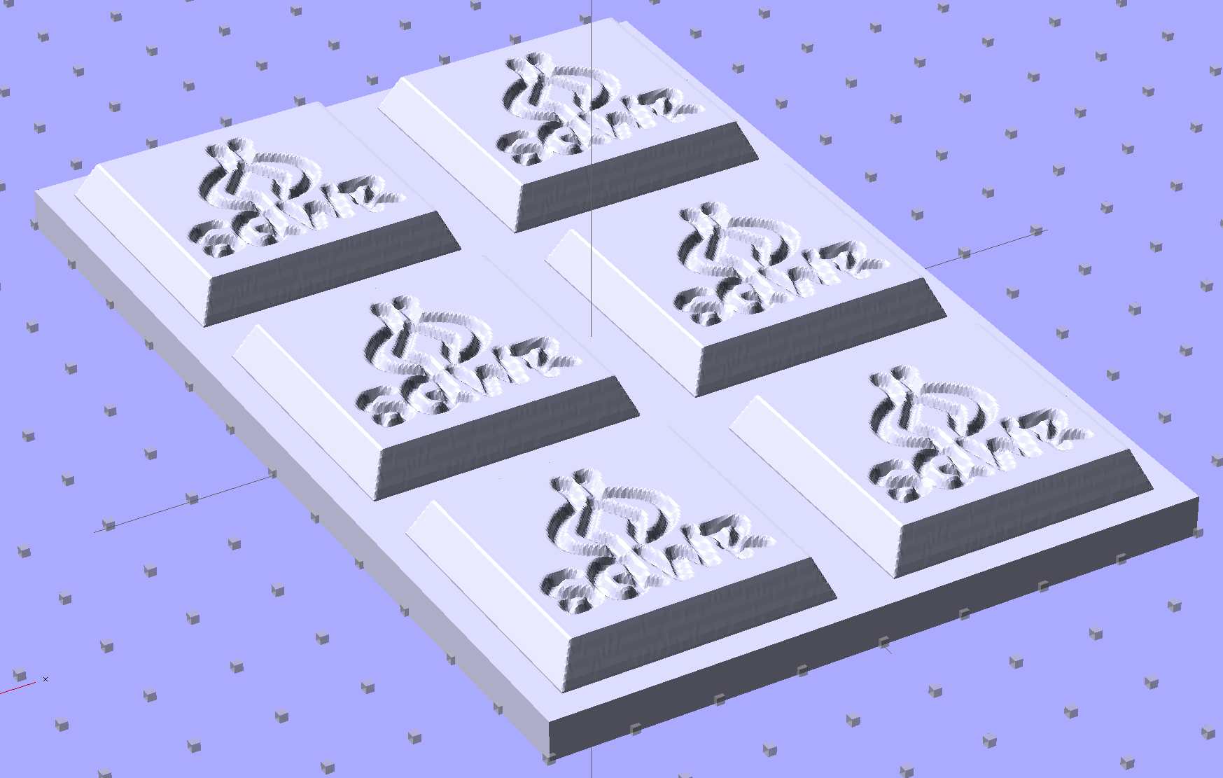
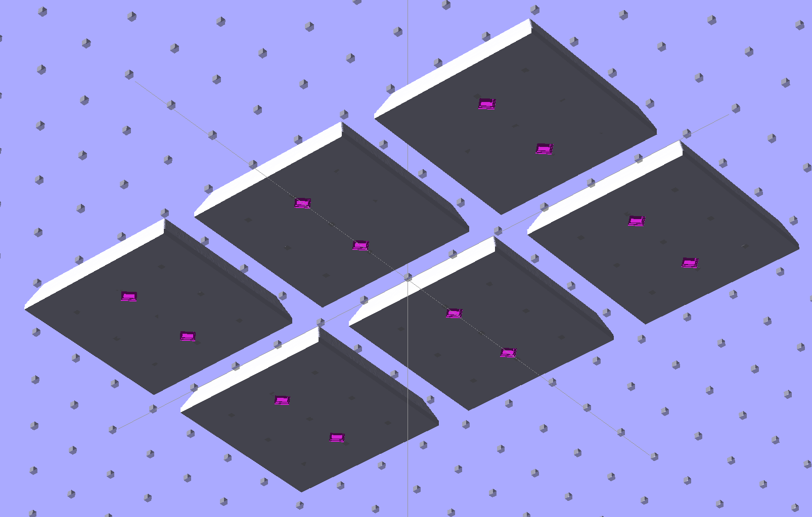
Then slide a plate under six copies to produce a positive model for a casting mold:
This is one of the few cases where the compiled-and-rendered version looks better, as though you’d shrink-wrapped it in gold foil:
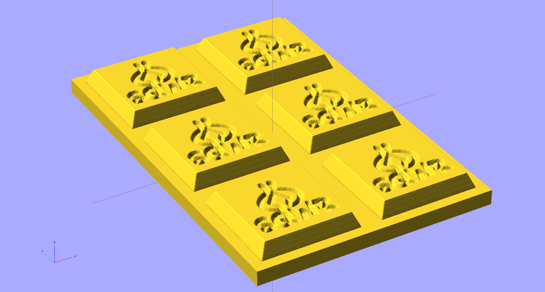
The height map STLs each have a bazillion tiny facets that take forever-and-a-day (well, the better part of half an hour for this set) to render, not to mention that the whole array would take two hours to print… and then be used once or twice to produce the flexy silicone negative mold.
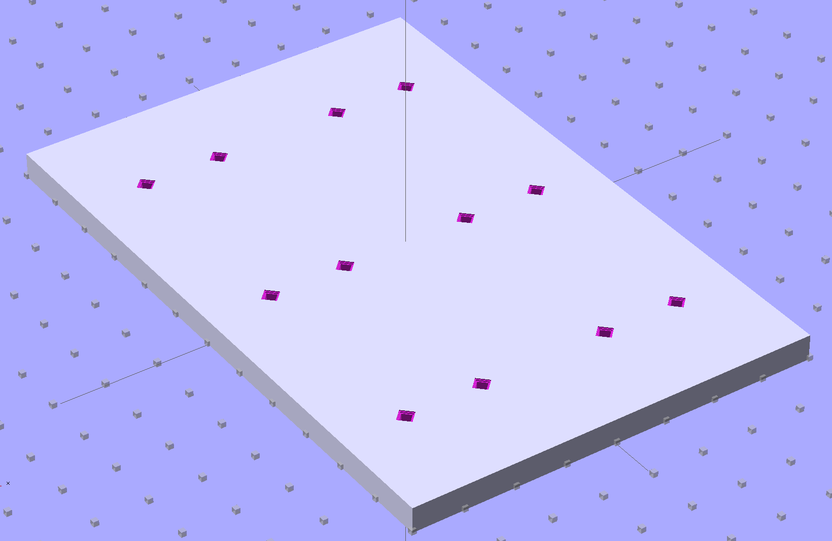
So it’s better to have a generic frame with alignment pin holes that you print once:
Better yet, just CNC-drill those holes in a nice, flat acrylic / polycarbonate slab.
Insert and glue filament snippets as alignment pins, trim about 1 mm over the surface to fit the small molds.
The OpenSCAD program can punch matching holes in the back of the small mold:
Or you could print out an array of the things with holes:
It’s not clear having OpenSCAD labor for half an hour to generate and emit a single STL file spanning all six molds is a win. Given that you don’t care about the mold-to-mold spacing, having Slic3r duplicate the same small STL file half a dozen (or more!) times would probably be a net win.
There’s no reason the OpenSCAD program that creates the original STL from the height map image can’t punch alignment pin holes, too, which would avoid this import-and-recompile step. If you’re going with a CNC-drilled plate, then it would make even more sense to not have a pair of OpenSCAD programs.
Anyhow.
Apply a handful of small molds to the backing plate with tapeless sticky, butter it up with mold release agent, slather on silicone putty, flip it over to produce a smooth surface “under” the small molds (so you can rest it flat on a table when pouring molten chocolate into the cavities), cure, peel, and you’d get a pretty good negative mold.
This may not make any practical sense, but it was easy & fun to see what’s possible…
The OpenSCAD source code:
// Positive mold framework for chocolate slabs
// Ed Nisley - KE4ZNU - January 2014

Layout = "FramePins";		// Molds FramePins FrameMolds Frame Single Pin

//- Extrusion parameters must match reality!
//  Print with 2 shells and 3 solid layers

ThreadThick = 0.20;
ThreadWidth = 0.40;

Protrusion = 0.1;			// make holes end cleanly

HoleWindage = 0.2;

//----------------------
// Dimensions

FileName = "SqWr-press.stl";	// overrride with -D

Molds = [2,3];					// count of molds within framework

MoldOC = [40.0,40.0];			// on-center spacing of molds
MoldSlab = 1.0;					// thickness of slab under molds

BaseThick = 5.0;

BaseSize = [(Molds[0]*MoldOC[0] + 0),(Molds[1]*MoldOC[1] + 0),BaseThick];
echo(str("Overall base: ",BaseSize));

PinOD = 1.75;					// locating pin diameter
PinLength = 2.0;				//  ... total length
PinSpace = 15.0;				// spacing within mold item

//----------------------
// Useful routines

//- Put peg grid on build surface

module ShowPegGrid(Space = 10.0,Size = 1.0) {

	RangeX = floor(100 / Space);
	RangeY = floor(125 / Space);

	for (x=[-RangeX:RangeX])
		for (y=[-RangeY:RangeY])
			translate([x*Space,y*Space,Size/2])
			%cube(Size,center=true);

}

module PolyCyl(Dia,Height,ForceSides=0) {			// based on nophead's polyholes

  Sides = (ForceSides != 0) ? ForceSides : (ceil(Dia) + 2);

  FixDia = Dia / cos(180/Sides);

  cylinder(r=(FixDia + HoleWindage)/2,
           h=Height,
	   $fn=Sides);
}

// Locating pin hole with glue recess
//  Default length is two pin diameters on each side of the split

module LocatingPin(Dia=PinOD,Len=0.0) {

	PinLen = (Len != 0.0) ? Len : (4*Dia);

	translate([0,0,-ThreadThick])
		PolyCyl((Dia + 2*ThreadWidth),2*ThreadThick,4);

	translate([0,0,-2*ThreadThick])
		PolyCyl((Dia + 1*ThreadWidth),4*ThreadThick,4);

	translate([0,0,-(Len/2 + ThreadThick)])
		PolyCyl(Dia,(Len + 2*ThreadThick),4);

}

module LocatingPins(Length) {
	for (i=[-1,1])
	translate([i*PinSpace/2,0,0])
		LocatingPin(Len=Length);
}

//-- import a single mold item

module MoldItem() {
	import(FileName,convexity=10);
}

//-- Overall frame shape

module Frame() {

	translate([0,0,BaseSize[2]/2])		// platform under molds
		cube(BaseSize,center=true);

}

//- Build it

ShowPegGrid();

if (Layout == "Pin")
	LocatingPin(Len=PinLength);

if (Layout == "Single")
	difference() {
		MoldItem();
		LocatingPins(PinLength);
	}

if (Layout == "Frame")
	Frame();

if (Layout == "Molds") {
	translate([-MoldOC[0]*(Molds[0] - 1)/2,-MoldOC[1]*(Molds[1] - 1)/2,0])
	for (i=[0:Molds[0]-1],j=[0:Molds[1]-1])
		translate([i*MoldOC[0],j*MoldOC[1],0])
			difference() {
				MoldItem();
				LocatingPins(PinLength);
			}
}

if (Layout == "FramePins")
	difference() {
		Frame();

		translate([-MoldOC[0]*(Molds[0] - 1)/2,-MoldOC[1]*(Molds[1] - 1)/2,0])
			for (i=[0:Molds[0]-1],j=[0:Molds[1]-1])
				translate([i*MoldOC[0],j*MoldOC[1],BaseSize[2]])
					LocatingPins(BaseThick);
	}

if (Layout == "FrameMolds") {
	Frame();
	translate([-MoldOC[0]*(Molds[0] - 1)/2,-MoldOC[1]*(Molds[1] - 1)/2,0])
		for (i=[0:Molds[0]-1],j=[0:Molds[1]-1])
			translate([i*MoldOC[0],j*MoldOC[1],BaseThick - MoldSlab + Protrusion])
			MoldItem();
}
