Ed Nisley's Blog: Shop notes, electronics, firmware, machinery, 3D printing, laser cuttery, and curiosities. Contents: 100% human thinking, 0% AI slop.
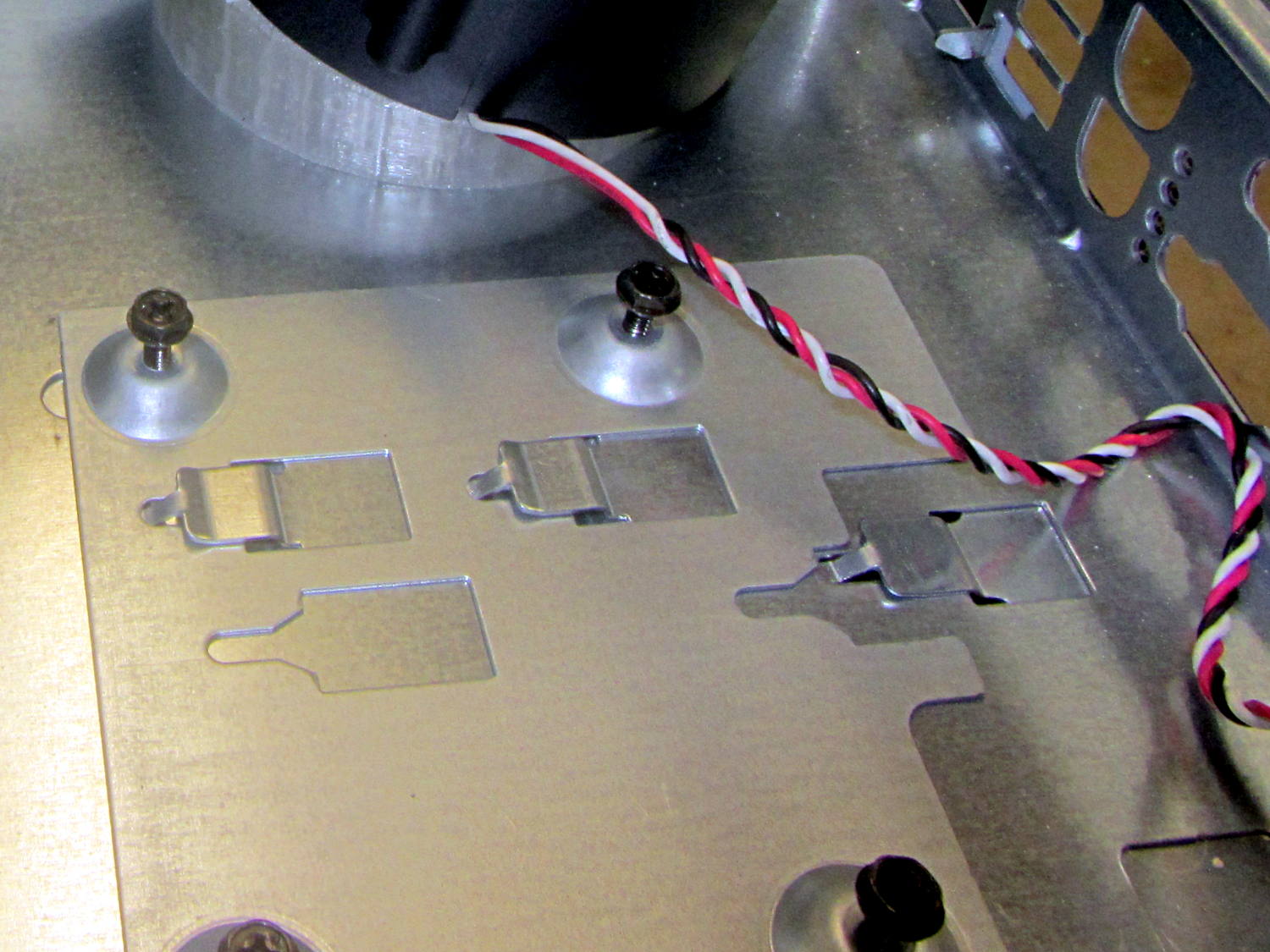
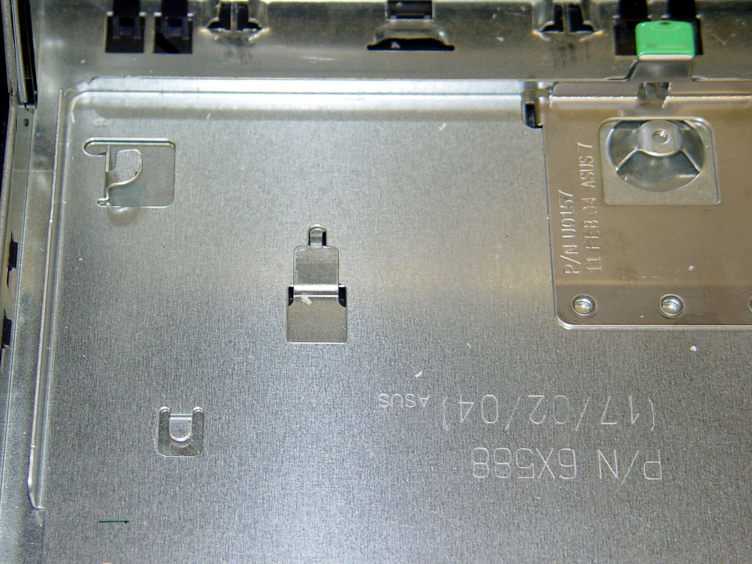
The Dell GX270 chassis has a small support plate under the CPU, evidently to support the heatsink and fan:
Optiplex GX270 CPU heatsink mount
It slides neatly into those clips on the system board tray, but it’s not actually locked into position. I think that allows it to slide around a bit under the system board, providing vertical support without constraining the board’s horizontal position. Anyhow, it looked like the easiest way to support the prototyping board that will hold the low voltage interface circuitry.
By some mischance, I found a nice aluminum plate exactly the right width, so only one side needed a saw cut and squaring. Coordinate drilling four #6 clearance holes matched the support:
LV Interface Adapter Plate – drilling
That corner of the tray had another system board retaining clip, but rather than bashing it flat, I just sawed a slit in the plate so it can slide right into position. Note the perfect alignment of that screw hole:
LV Interface Adapter Plate – retainer
I love it when all my mistakes cancel out!
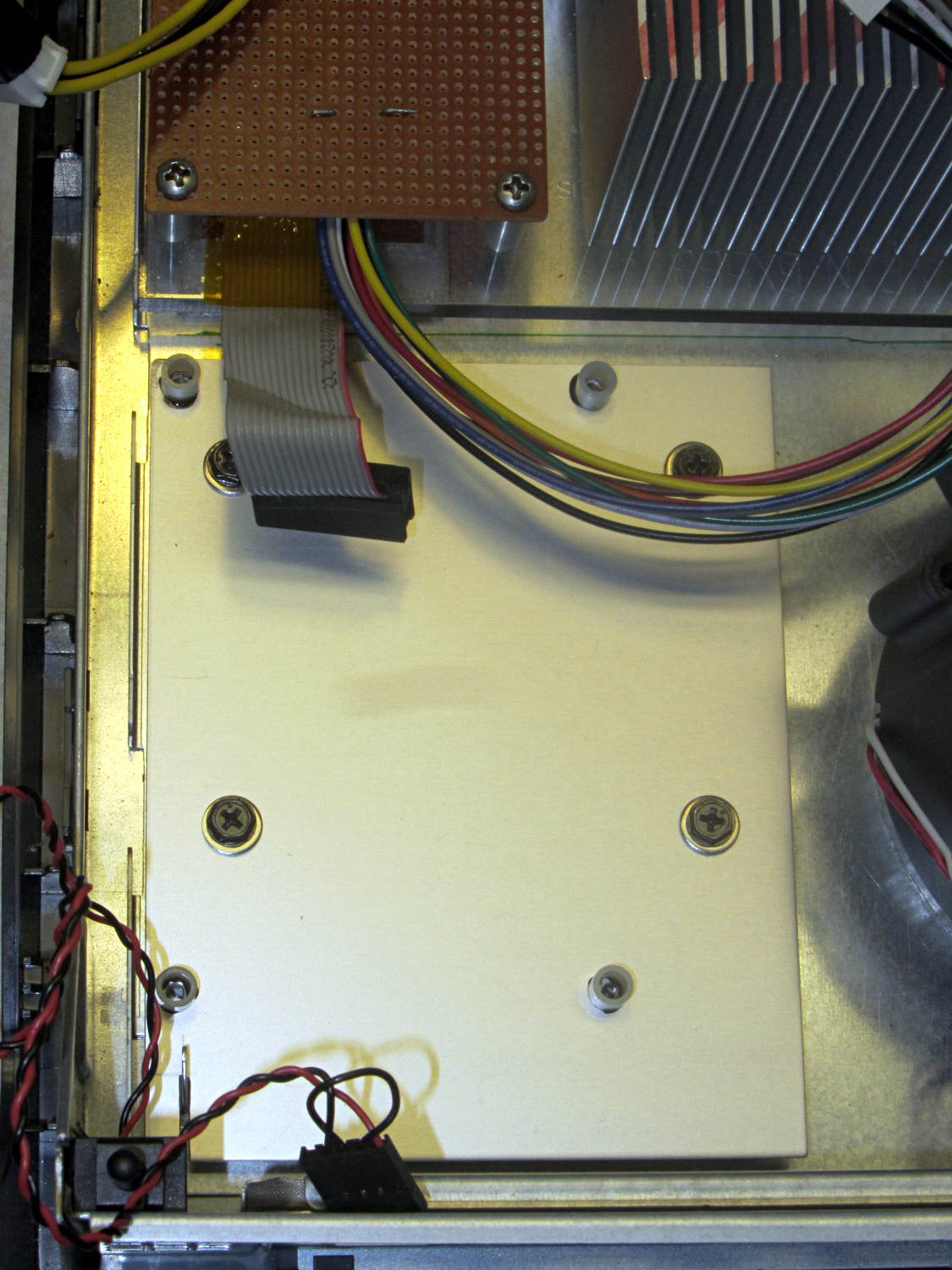
Four more holes matched the prototyping circuit board and, while I had some epoxy mixed up for another part, I fastened four standoffs over the holes. A washer under each original screw soaked up exactly enough space that the screws barely indented the case and, as if by magic, hold the support plate firmly in place:
LV Interface Adapter Plate – installed
Of course, that means I must remove the circuit board to get the tray out, but the AC interface board must also come out, so we’re not talking a spur-of-the-moment operation.
The switch in the lower left corner is the original Dell “intrusion monitoring” switch harvested from a complex metal stamping in the diagonally opposite corner of the case. It’s epoxied to the case wall, with the plunger contacting a shim epoxied to the top of the case, and will eventually disconnect the AC line power from the drive electronics: case open = switch closed = lethal power off.
Back in the day, heatsinks like this sat atop Moah Powah Pentium CPUs:
ET227 transistor on heatsink
I picked it because the hulking ET227 transistor fit neatly on its backside, it seemed capable of handling 30 to 50 W of power, and I have several of them in the Big Box o’ Heatsinks. No careful thermal analysis was involved…
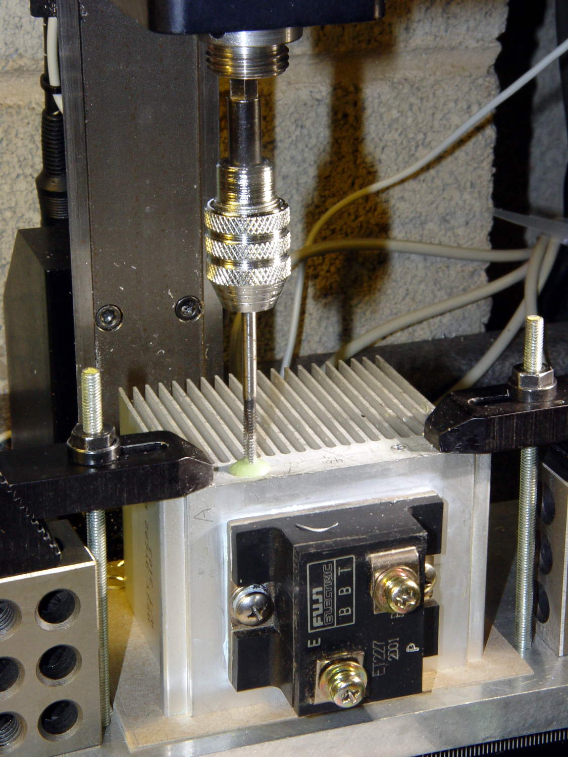
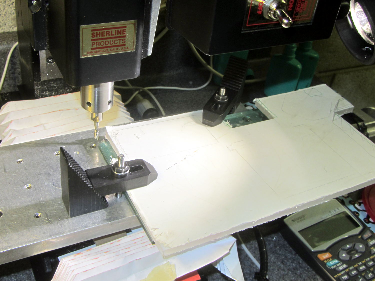
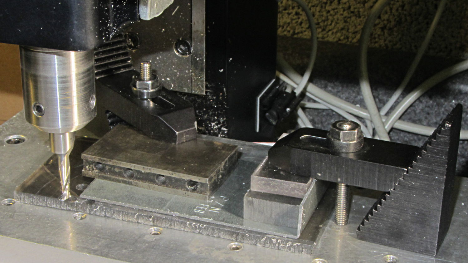
Mounting it on the polycarbonate sheet inside the repurposed GX270 case involved drilling & tapping a pair of 6-32 holes in one side:
ET227 Heatsink – tapping
That’s not rigid tapping on a Sherline, it’s aligning a hand-turned tap in the spindle bore. Sorry.
And, yeah, you’re not supposed to leave the semiconductors mounted when you’re drilling the heatsink. I figure there’s nothing I can possibly do without using a hammer that will bother that transistor in the slightest. What, me worry?
The transistor collector runs at line voltage, which means the entire heatsink will pose a lethal shock hazard. I thought about isolating the collector and failed to come up with anything I’d trust to be both thermally conductive and electrically insulating over the long term; the screw heads must be isolated from the collector plate, too.
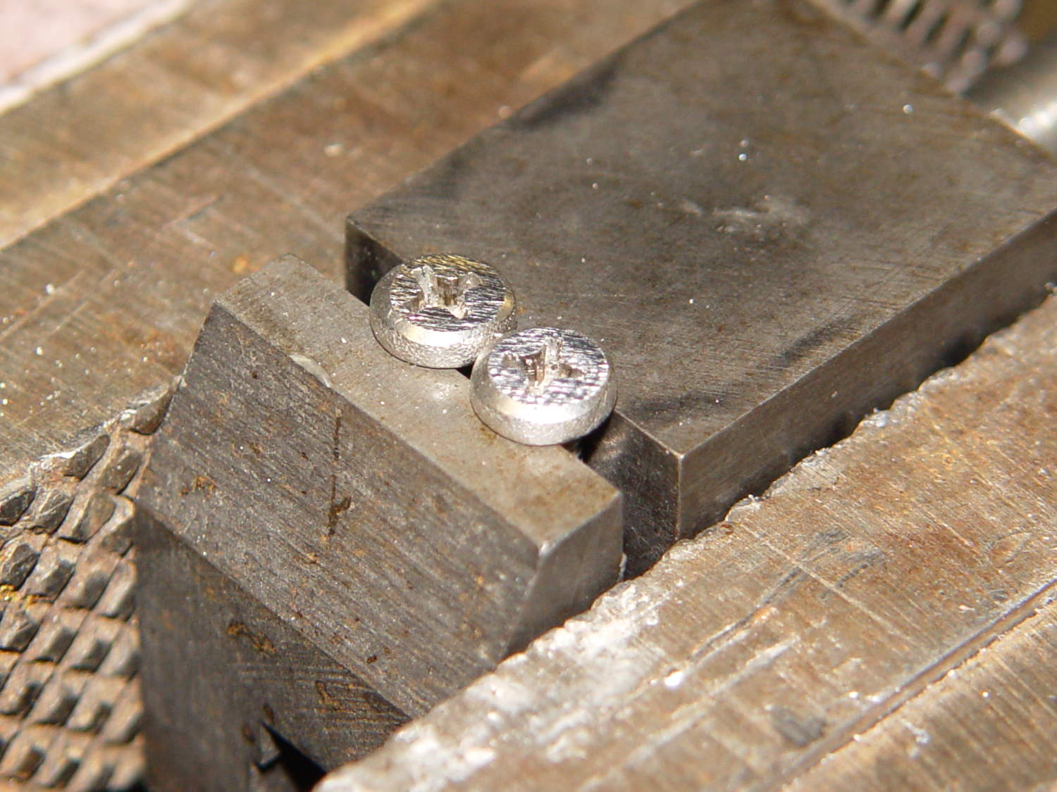
The screws stick out below the polycarbonate sheet, just above the grounded EMI shell lining the case, so I flattened them a bit:
ET227 Heatsink – mounting screws
The simple rectangular strip to the rear of the chassis mounting clips is just slightly thicker than the screw heads, so they can’t possibly contact the case:
Chassis Clips
It gets glued to the underside of the nearly invisible sheet:
ET227 heatsink – gluing screw shield
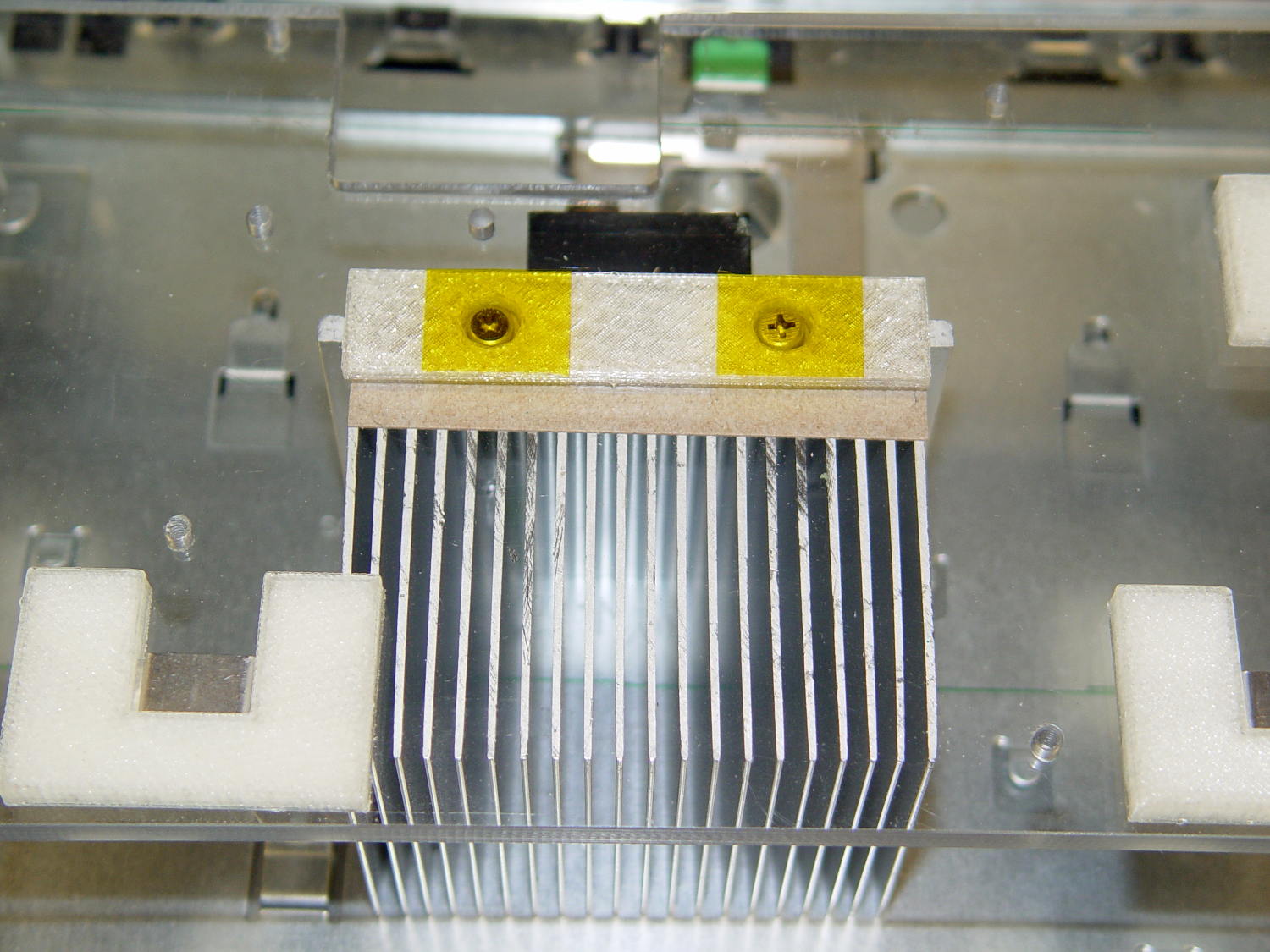
With Kapton tape over the heads, Just In Case:
ET227 Heatsink – mounted
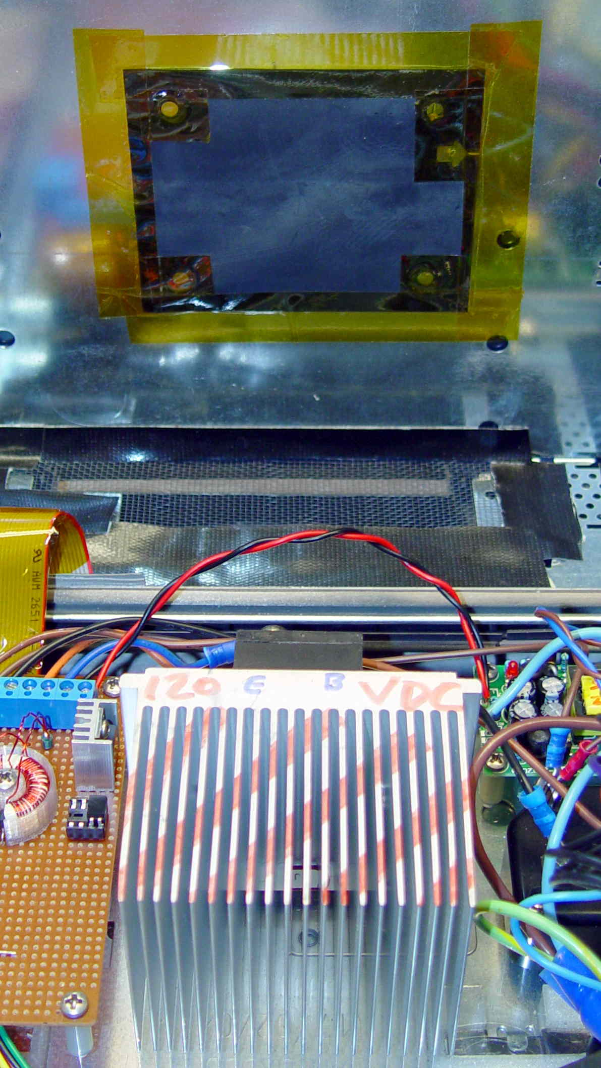
It makes a nice linear counterpoint to the jumble of AC interface wiring:
AC Interface Chassis
The insulating sheet on the case lid came from the bottom of the original GX270 system board, where I think it served much the same purpose. It’s surely not rated for AC line voltages, but the thought must count for something:
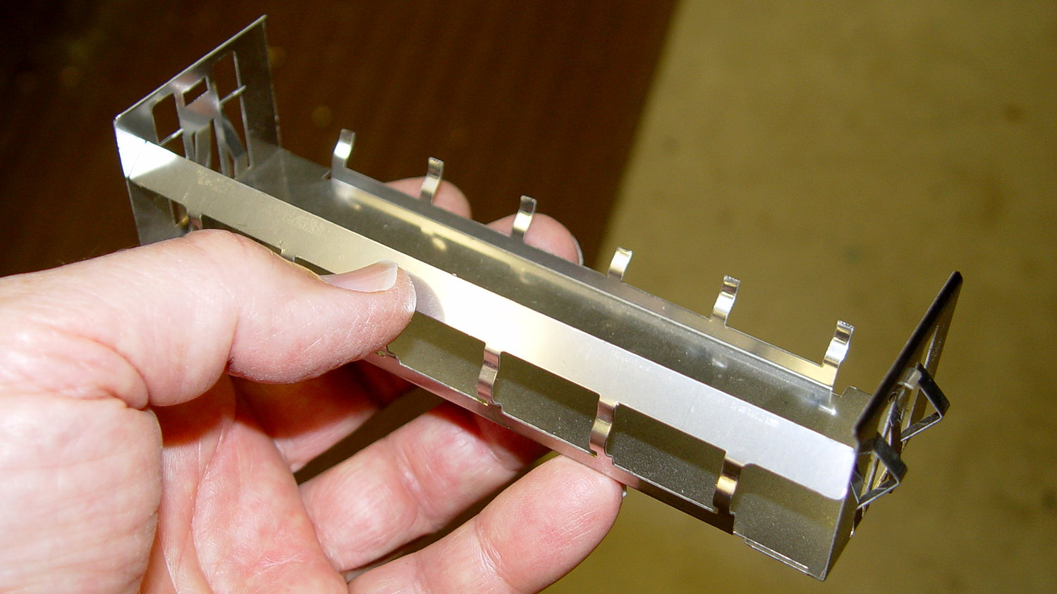
The Dell GX270 system board mounts on a tray, latching into small tabs, with a single screw locking it in place. The tray then slides into the metal EMI shield / case, latching onto more tabs, with a spring-loaded pair of tabs snapping into a slot under the green latch:
Optiplex GX270 – system board tray
All that is well and good for a mass-production PC system board, but poses a problem for mounting anything else: there’s no room for screw heads below the tray, adhesives really don’t bond to slightly flexible aluminum sheets, and I definitely can’t do large-scale precision metal bending.
So a cheat seems in order. The general idea is to support a 6 mm polycarbonate sheet on clips that slide under the small tabs along the front, support the sheet on the rear tabs, and secure it with the screw. That’s thick enough to allow tapping holes for mounting screws, so everything else can mount to the sheet.
The sheet fits around the power supply on the right, protrudes over the rear of the tray to the back of the case (with a recess around the green latch), and clears the hinge assembly on the left. There are no dimensions, as it’s all done by eye with the Joggy Thing.
AC Chassis Shaping
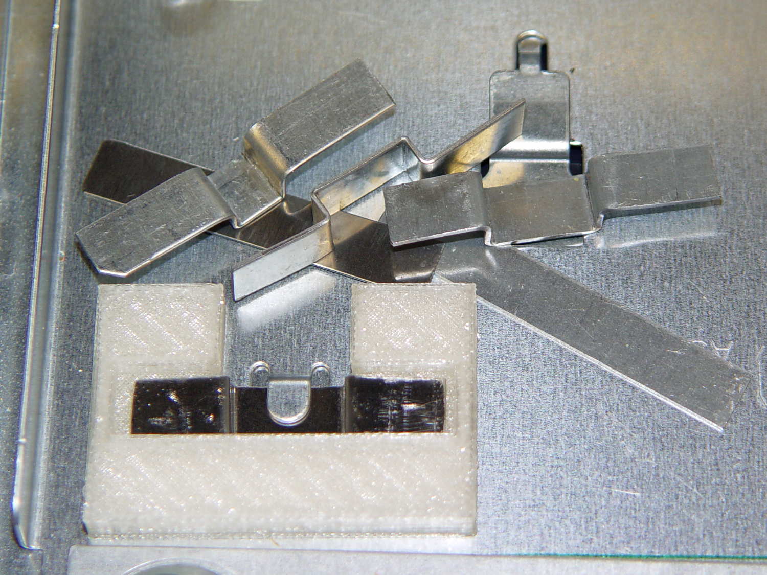
A drive bay EMI plug from a long-discarded PC provided some nice springy steel strips that slide neatly under those tray tabs:
Drive EMI shield
That actually took a bit of trial-and-error:
AC Chassis mounting brackets – practice makes perfect
My first attempts used slightly thicker steel that didn’t fit nearly as well, plus I wasn’t quite sure how wide they should be.
As with nearly all plastic doodads around here, the white plastic mounting clips / brackets come from the M2:
Chassis Clips
The two brackets in the middle of the solid model slide around the tabs at the rear corners of the tray and capture the bent-over top section below the polycarbonate sheet.
The strip in the rear goes around the screws holding the heatsink to the sheet; more on that later.
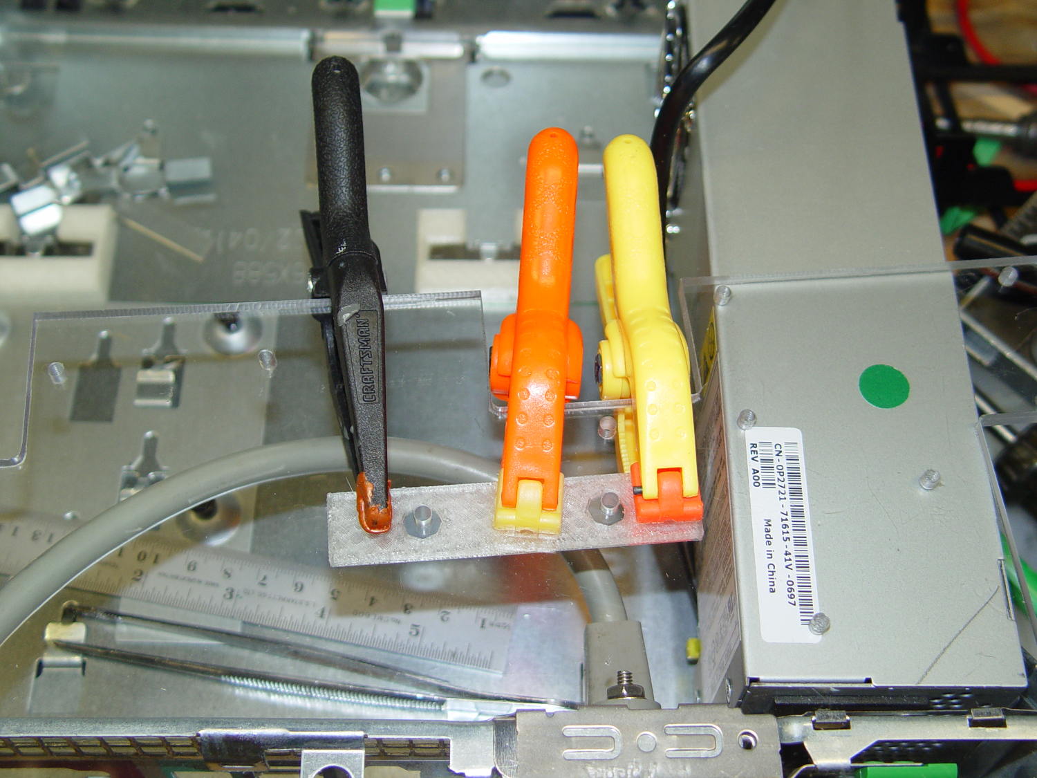
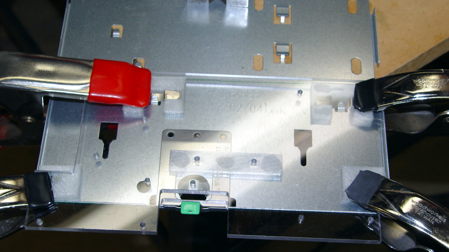
The PLA brackets get themselves glued to the sheet with IPS #4 solvent adhesive, a hellish mixture of chlorinated hydrocarbons that attacks most plastics with gleeful enthusiasm. I positioned the brackets on the tray, slobbered adhesive on their tops, slapped the polycarbonate sheet in place, and applied clamps:
AC Chassis – gluing bracket blocks
The final bonds weren’t as uniform as I’d like, but they seem rugged enough. The lip along the rear of the tray was slightly higher on the left edge, which may have interfered with the clamping pressure; it’s obviously not a controlled dimension.
The tapped holes in the sheet accommodate screws for various bits & pieces.
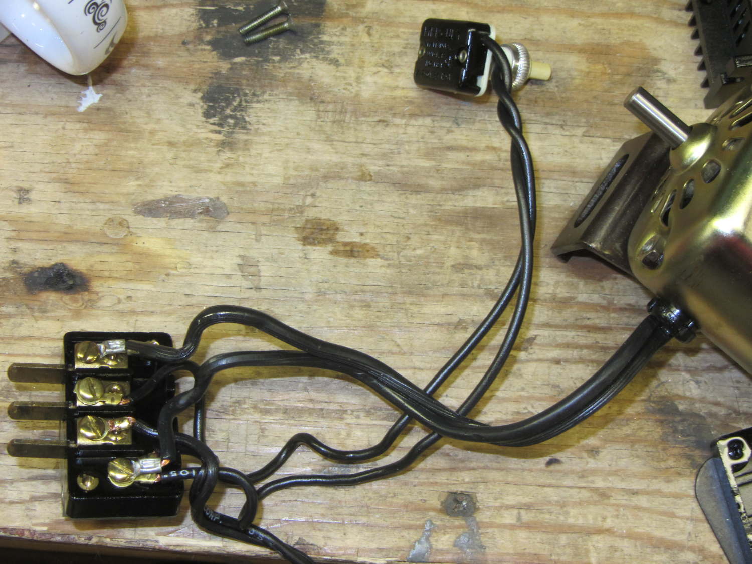
The original Kenmore Model 158 sewing machine used a two-wire line cord:
Kenmore 158 – terminal block
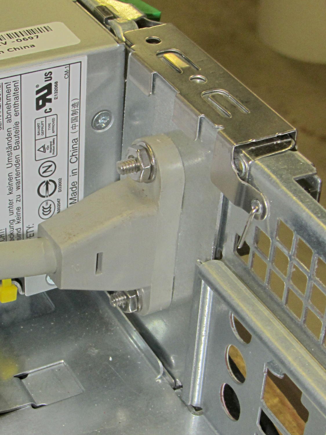
In light of my modifications, grounding the frame seems prudent. The heap produced a long IEC extension cord with screw-mounting ears on the socket end that fit neatly into the GX270’s rear panel area occupied by two PCI cover plates, so a bit of Quality Shop Time seemed in order.
The GX270’s carcass yielded a complex bit of sheet metal that held the hard drive and a few other odds & ends, with some clean right-angle bends in exactly the right places:
Dell drive bracket – intact
Some bandsaw work removed the gimcrackery:
Dell drive bracket – first bandsaw pass
More bandsawing produced a rough outline:
Dell drive bracket – second bandsaw pass
Sawing to length, removing the small flanges, and squaring the sides:
Dell drive bracket – squaring edges
I traced the existing PCI cover tabs, bandsawed the outlines, and filed to suit:
Dell drive bracket – basic outline
They look a bit ragged, but fit well enough:
Dell drive bracket – trial fit – interior
From the outside, it looks like it grew there:
Dell drive bracket – trial fit – exterior
The divider between the PCI slots succumbed to tin snips and a bit of filing. The tabs climbing over the bottom edge come from the internal EMI shield covering the entire back surface.
A bit of coordinate drilling and manual milling produced the IEC socket outline
Dell drive bracket – drilling and milling
Which looks pretty good from the inside:
Dell drive bracket – IEC socket – interior
And great from the outside, if I do say so myself:
Dell drive bracket – IEC socket – exterior
Match-drilling a #6 clearance hole below the hole in the clamp arm, then ramming a self-tapping case screw into it, provides a convenient grounding point for the sewing machine cord:
IEC Socket Mount – ground screw
The chassis lid has two matching holes for those screw heads, which would ordinarily hold the two PCI cards in place. I could remove the clamp arm, but it doesn’t get in the way of anything.
Dell built the GX270 I’m repurposing back in 2004, early on in the capacitor plague years, but only one of the system board caps showed signs of leakage:
Capacitor plague – 2004 Dell Edition
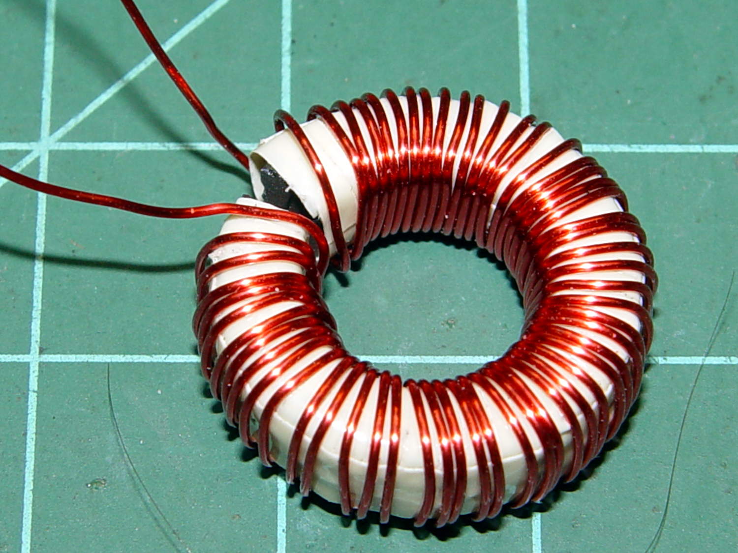
While I was harvesting some of the connectors, it occurred to me that those powdered iron inductors might make good current sensors, as they’re already wound with heavy gauge copper wires.
I picked an inductor with enough turns and, although slitting didn’t pose much of a problem, the saw did make a mess of the turns adjacent to the cut:
Powdered iron toroid – slitting
Iron powder has more magnetic remnance than ferrite, to the extent that iron swarf clogged the gap. After the first pass, I ran the slit toroid through the degausser to shake it clean and see what damage had been done. It looked OK, so I realigned it on the saw blade and continued the mission, with all the dust vanishing into the vacuum cleaner’s snout.
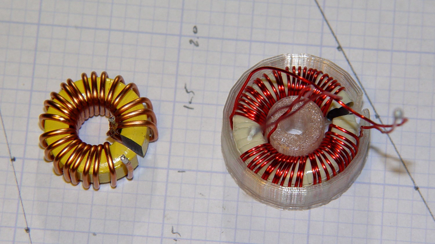
Removing the damaged sections left 22 turns. For comparison, I converted the 56 turn ferrite toroid into a 25 turn model by paralleling two 25 turn sections:
Slit toroids – iron – ferrite
The enamel wire on the iron toroid measures 40 mil diameter, close enough to 18 AWG.
Paralleling two 24 AWG windings on the ferrite toroid produces twice the copper area of a single winding, so the resistance is the same as a single 21 AWG winding (3 AWG steps = factor of two area change). That’s three steps smaller than the 18 AWG on the iron toroid, so the resistance is a factor of two larger than the heavier wire.
The paralleled winding has the advantage of reducing the power dissipation required to produce the same magnetic flux density, without the difficulty of winding heavier wire. That may not actually matter, given the relatively low currents required by the motor in normal operation.
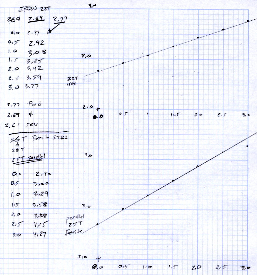
Wedging a Hall sensor into the gaps and stepping the current produced two useful graphs:
Iron and ferrite toroids – Hall sensor output
The iron toroid has lower permittivity (less flux density for a given magnetizing force), which means the full-scale range exceeds 3 A and the useful range up to 1 A covers only 300 mV.
The last point on the ferrite curve shows the Hall sensor output saturating just over 4 V, with 1.5 V of range.
The slope, in mV/A
Powdered iron: 340
Ferrite: 540
Boosting the slope of the powdered iron by 25/22 gives 386 mV/A, so the iron permeability really is 70% of the ferrite. That’s modulo the gap size, of course, which surely differs by enough to throw out all the significant digits.
Obviously, an op amp circuit to remove the offset and rescale the output to 0-5 V will be in order.
The previous graph for the ferrite toroid with the complete 56 turn winding shows, as expected, about twice the output of this 25 turn version:
FT82-43 – 56 turns – 24 AWG
The linear part of that line is 1375 mV/A, although I can’t vouch that the data came from the same Hall effect sensor. Scaling it by 25/56 gives 613 mV/A, suggesting it’s not the same sensor.
Having developed an emotional attachment to the ferrite toroid, I’ll use it in the first pass of the current feedback circuit. If the motor need a bit less sensitivity or lower resistance, the powdered iron toroid looks like a winner.
Memo to self: Always degauss iron toroids before slitting!
Mary bought a pair of Revlon tweezers a while ago, picking a Name Brand to avoid hassles with bottom-dollar crap:
Revlon tweezers – bad spot welds
Well, that didn’t work.
I contend that the only difference between Name Brands and the bottom-dollar crap I tend to buy is a bit of QC and a lot of price. I’ll agree that’s not strictly true, but it does fit a goodly chunk of the observed data.
Anyhow.
I milled a recess into the corner of some scrap plastic to locate the handle end, then arranged a step block to capture the business end:
Revlon tweezers – drilling setup
That setup ensures the holes go into the corresponding spots on both pieces, because I couldn’t figure out how to clamp them together and drill them both at once. I drilled the other piece with its good side up to align the holes; doing it bad side up would offset the holes if they’re not exactly along the center line.
A closer look:
Revlon tweezers – drilling fixture
Talk about a precarious grip on the workpiece!
I filed the welds flat before drilling, so the pieces lay flat and didn’t distract the drill.
Then:
Center-drill
Drill 2-56 clearance
Scuff up mating surfaces with coarse sandpaper
Apply epoxy
Insert screws
Add Loctite
Tighten nuts to a snug fit
Align jaws
Tighten nuts
Fine-tune jaw alignment
Apply mild clamping force to hold jaws together
Wait overnight
Saw screws and file flush
Done!
The clamping step:
Revlon tweezers – epoxy curing
Those nicely aligned and ground-to-fit jaws were the reason Mary bought this thing in the first place.
The screw heads look OK, in a techie sort of way:
Revlon tweezers – fixed – front
The backside won’t win any awards:
Revlon tweezers – fixed – rear
But it won’t come apart ever again!
There’s surely a Revlon warranty covering manufacturing defects, printed on the long-discarded packaging, that requires mailing the parts with the original receipt back to some random address at our own expense.
I’m pretty sure that chip at 1 o’clock happened while it was clamped in the vise between two cardboard sheets, but I haven’t a clue as how it got that much force. In any event, that shouldn’t affect the results very much, right up until it snaps in two.
Although the current will come from a (rectified) 120 VAC source, the winding will support only as much voltage as comes from the IR drop and inductive reactance, which shouldn’t be more than a fraction of a volt. Nevertheless, I wound the core with transformer tape:
FT82-43 toroid – wrapped
That’s 3M 4161-11 electrical tape (apparently out of production, but perhaps equivalent to 3M’s Super 10 tape) cut into half-foot lengths, slit to 100 mils, and wrapped ever so gently.
The thickest offering from the Big Box o’ Specialty Wire was 24 AWG, so that’s what I wound on it:
FT82-43 toroid – wound
That’s 56 turns, which should convert 2.2 A into 1000 G (enough to max out the Hall effect sensor) and is more in keeping with 24 AWG wire’s 3.5 A current rating.
The insulated core requires just under 1 inch/turn, so figure the length at 56 inch. The wire tables show 26.2 Ω/1000 ft, so the DC winding resistance should be 120 mΩ. My desk meter has 0.1 Ω resolution, which is exactly the difference between shorted probes and probes across the coil: close enough.
The inductance is 170 µH, so the inductive reactance at 120 Hz = 128 mΩ.