We rode the Feeder Canal trail during a recent bike vacation in exotic Glens Falls NY:
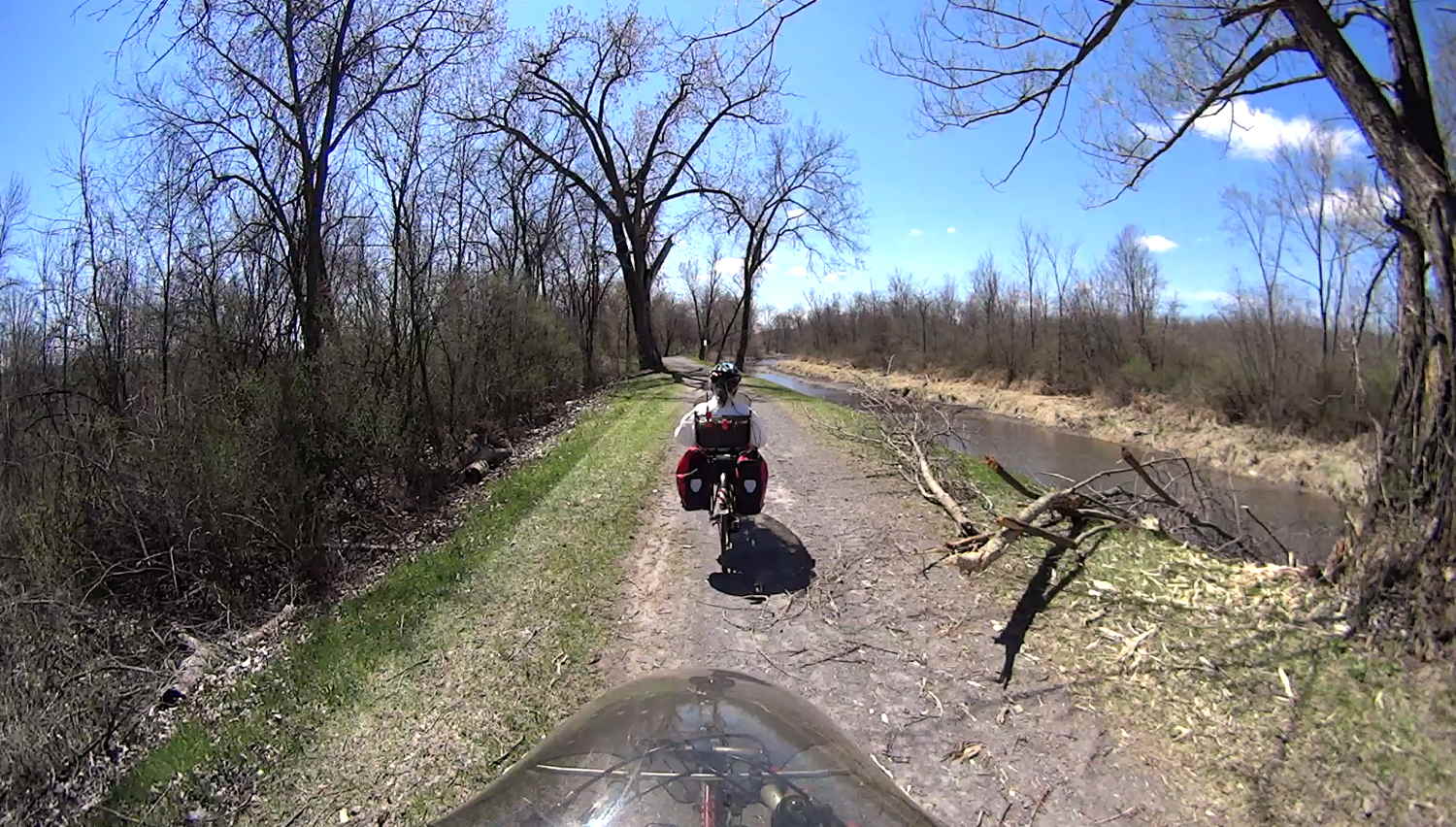
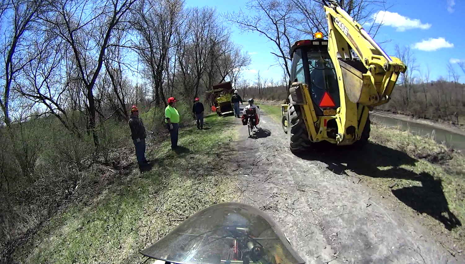
The numerous downed branches along the trail and countless twigs on the trail came from a brush-clearing operation:
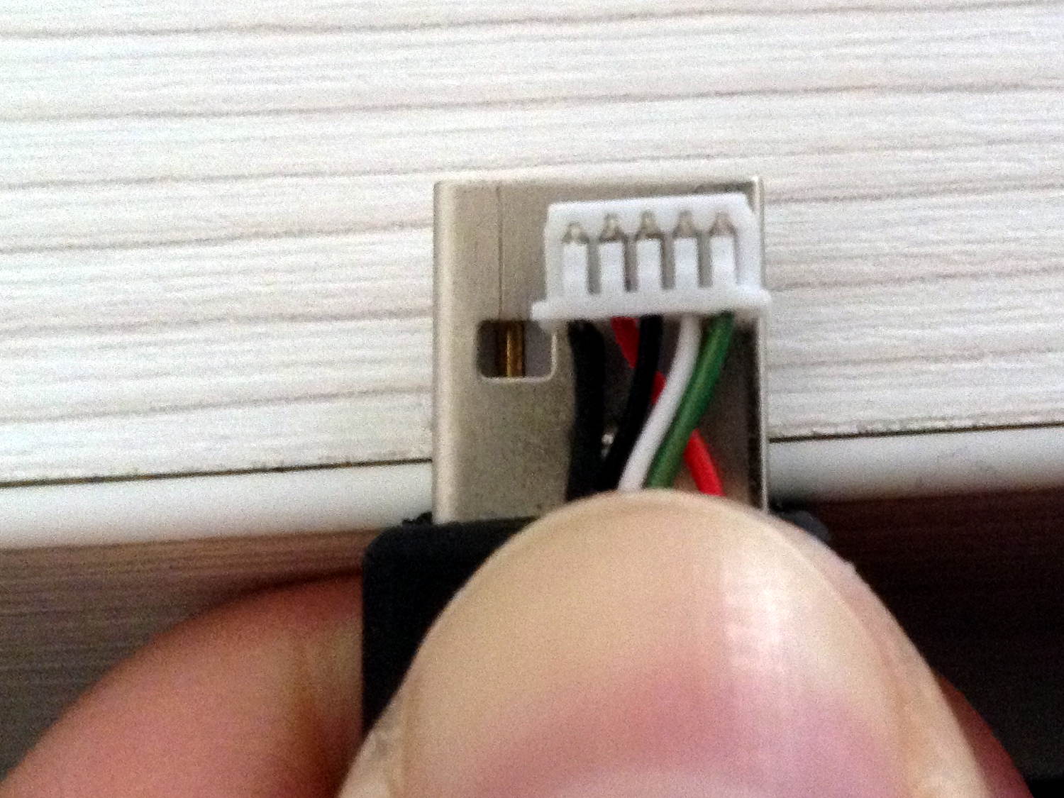
As luck would have it, a twig snagged between my front tire and fender, snapping the clips holding the fender in place:
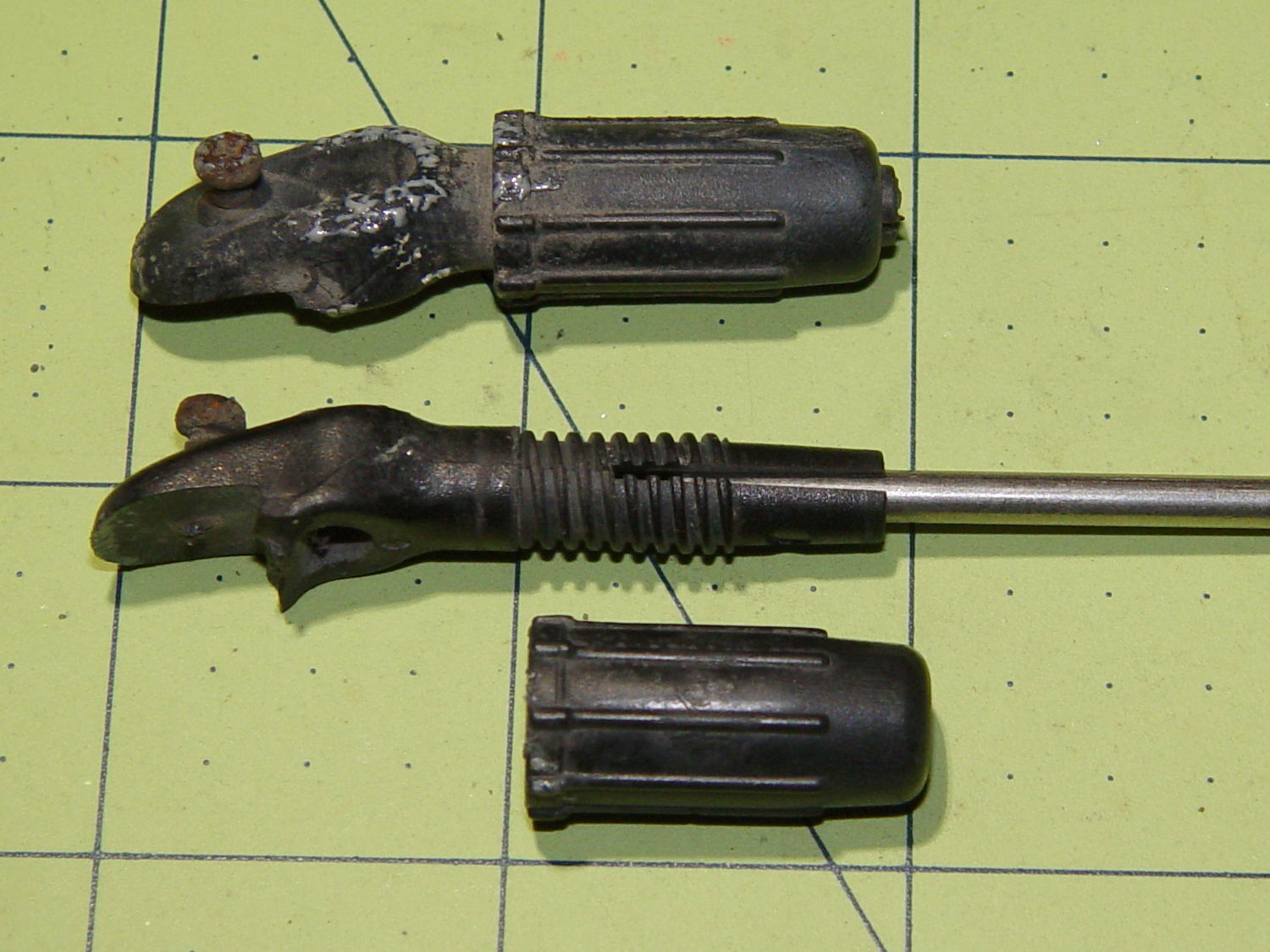
Should it not be obvious, each ferrule formerly had two parallel jaws (on the left) gripping the fender, with the tiny screw digging into the fender. I affixed the fender to the broken clips with copious amounts of duct tape and we continued the mission.
It should be obvious why those ferrules are not suitable for 3D printing.
However, with the recent rear fender clip serving as inspiration, this didn’t take long:
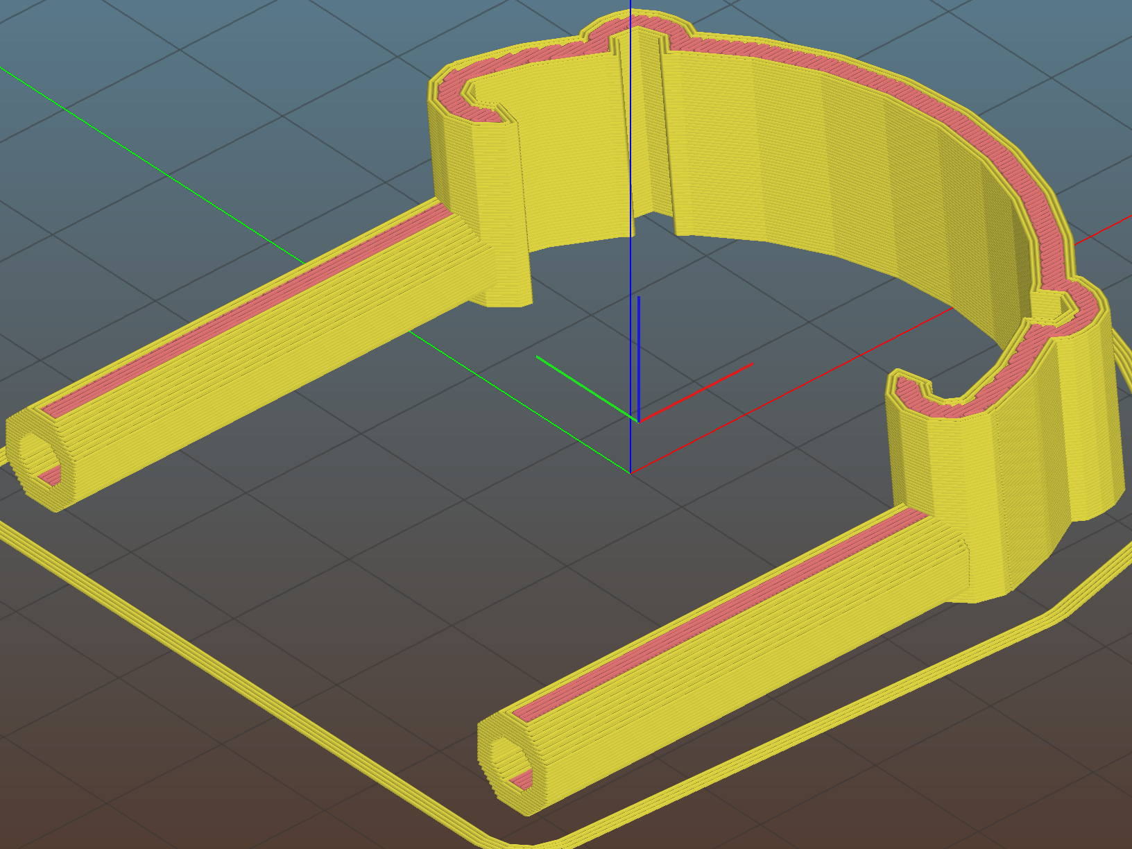
The front fender fits a 20 inch wheel and is somewhat wider and flatter than the rear fender (I think they bent the same plastic strip around a smaller mandrel), so I did a quick copy-and-paste hack job on the OpenSCAD source code, rather than trying to parameterize the daylights out of the previous model.
The posts around the wire stays are 6 diameters deep and reamed to fit; the stays won’t be flopping around even without fiddly mechanical hardware retaining them. The holes extend about halfway into those posts to mimic the dimensions of the original ferrules.
All of us can predict where the next break will occur, right? That’s OK: I want this to break, instead of wrecking the fender, so the only question is how much abuse those simple joints can withstand. The printing orientation wraps the perimeter threads from the posts around the clip, making it about a strong as it can be.
The ferrules should splay outward by a few degrees to match the angle from the fender to the fork eyelets, but that’s in the nature of fine tuning.
The arch accommodates a strip of double-sided foam tape holding the clip in place along the fender curve, with those cute little hooks capturing the fender to keep the tape in compression:
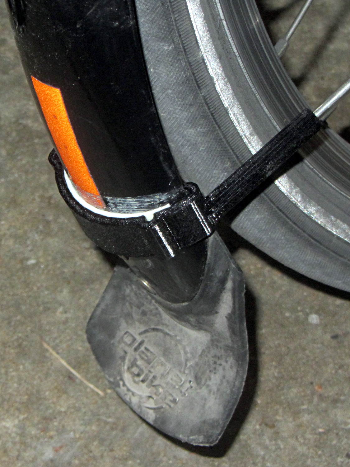
I really must get some black foam tape …
The picture shows the fender sitting well away from the tire, due to the upper fender mount bending in response to the splash flap snagging on curbs and random debris; the wire stays didn’t seat completely into the posts.
The extender I made during the cracked fork episode remained perfectly straight, though:
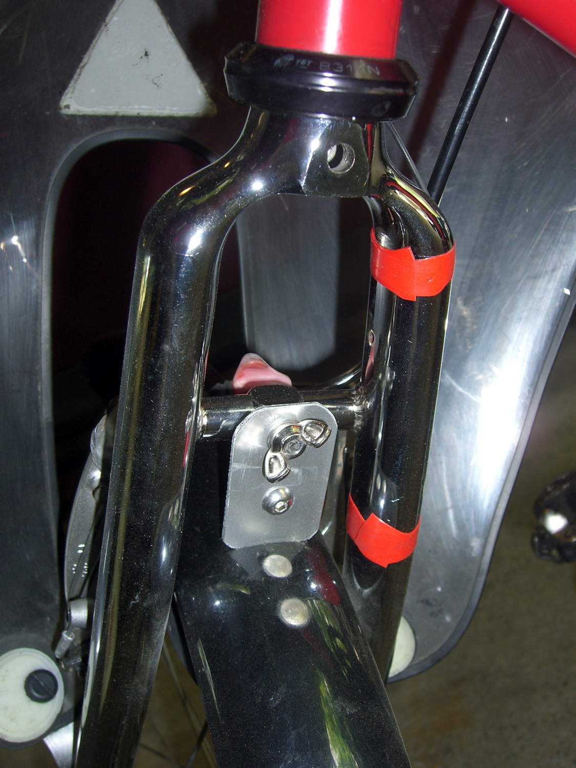
So I re-bent the upper fender mount (not the extender!) to its original angle, thereby moving the bottom of the fender much closer to the tire. Now the stays seat fully, the clip holds the fender firmly in place with no rattles, and it’s all good.
The OpenSCAD source code as a GitHub Gist:
| // Tour Easy front fender clip | |
| // Ed Nisley KE4ZNU April 2017 | |
| Layout = "Clip"; // Build Profile Ferrule Clip | |
| //- Extrusion parameters must match reality! | |
| ThreadThick = 0.25; | |
| ThreadWidth = 0.40; | |
| HoleWindage = 0.2; | |
| Protrusion = 0.1; // make holes end cleanly | |
| inch = 25.4; | |
| function IntegerMultiple(Size,Unit) = Unit * ceil(Size / Unit); | |
| //———————- | |
| // Dimensions | |
| // special case: fender is exactly half a circle! | |
| FenderC = 51.0; // fender outside width = chord | |
| FenderM = 21.0; // height of chord | |
| FenderR = (pow(FenderM,2) + pow(FenderC,2)/4) / (2 * FenderM); // radius | |
| echo(str("Fender radius: ", FenderR)); | |
| FenderD = 2*FenderR; | |
| FenderA = 2 * asin(FenderC / (2*FenderR)); | |
| echo(str(" … arc: ",FenderA," deg")); | |
| FenderThick = 2.5; // fender thickness, assume dia of edge | |
| ClipHeight = 15.0; // top to bottom, ignoring rakish tilt | |
| ClipThick = 3.0; // thickness of clip around fender | |
| ClipD = FenderD; // ID of clip against | |
| ClipSides = 4 * 8; // polygon sides around clip circle | |
| BendReliefD = 2.5; // bend arch diameter | |
| BendReliefA = 2/3 * FenderA/2; // … angle from dead ahead | |
| BendReliefCut = 1.0; // factor to thin outside of bend | |
| ID = 0; | |
| OD = 1; | |
| LENGTH = 2; | |
| StayDia = 3.3; // fender stay rod diameter | |
| StayOffset = 23.0; // stay-to-fender distance | |
| StayAngle = -5; // angle from stay to fender | |
| FerruleSides = 2*4; | |
| Ferrule = [StayDia,3*FenderThick/cos(180/FerruleSides),6*StayDia + StayOffset]; // ID = stay rod OD | |
| //———————- | |
| // Useful routines | |
| module PolyCyl(Dia,Height,ForceSides=0) { // based on nophead's polyholes | |
| Sides = (ForceSides != 0) ? ForceSides : (ceil(Dia) + 2); | |
| FixDia = Dia / cos(180/Sides); | |
| cylinder(r=(FixDia + HoleWindage)/2, | |
| h=Height, | |
| $fn=Sides); | |
| } | |
| //———————- | |
| // Clip profile around fender | |
| // Centered on fender arc | |
| module Profile(HeightScale = 1) { | |
| linear_extrude(height=HeightScale*ClipHeight,convexity=5) { | |
| difference() { | |
| offset(r=ClipThick) // outside of clip | |
| union() { | |
| circle(d=ClipD,$fn=ClipSides); | |
| for (i=[-1,1]) | |
| rotate(i*BendReliefA) { | |
| translate([ClipD/2 + BendReliefD/2,0,0]) | |
| circle(d=BendReliefD,$fn=6); | |
| } | |
| } | |
| union() { // inside of clip | |
| circle(d=ClipD,$fn=ClipSides); | |
| for (i=[-1,1]) | |
| rotate(i*BendReliefA) { | |
| translate([ClipD/2 + BendReliefCut*BendReliefD/2,0,0]) | |
| circle(d=BendReliefD/cos(180/6),$fn=6); | |
| translate([ClipD/2,0,0]) | |
| square([BendReliefCut*BendReliefD,BendReliefD],center=true); | |
| } | |
| } | |
| translate([(FenderR – FenderM – FenderD/2),0]) // trim ends | |
| square([FenderD,2*FenderD],center=true); | |
| } | |
| for (a=[-1,1]) // hooks around fender | |
| rotate(a*(FenderA/2)) | |
| translate([FenderR – FenderThick/2,0]) { | |
| difference() { | |
| rotate(1*180/12) | |
| circle(d=FenderThick + 2*ClipThick,$fn=12); | |
| rotate(1*180/8) | |
| circle(d=FenderThick,$fn=8); | |
| rotate(a * -90) | |
| translate([0,-2*FenderThick,0]) | |
| square(4*FenderThick,center=false); | |
| } | |
| } | |
| } | |
| } | |
| //———————- | |
| // Ferrule body | |
| module FerruleBody() { | |
| translate([0,0,Ferrule[OD]/2 * cos(180/FerruleSides)]) | |
| rotate([0,-90,0]) rotate(180/FerruleSides) | |
| difference() { | |
| cylinder(d=Ferrule[OD],h=Ferrule[LENGTH],$fn=FerruleSides,center=false); | |
| translate([0,0,StayOffset + Protrusion]) | |
| PolyCyl(Ferrule[ID],Ferrule[LENGTH] – StayOffset + Protrusion,FerruleSides); | |
| } | |
| } | |
| //———————- | |
| // Generate entire clip at mounting angle | |
| module FenderClip() { | |
| union() { | |
| translate([FenderR,0,0]) | |
| difference() { // angle and trim clip | |
| rotate([0,StayAngle,0]) | |
| translate([-(FenderR + ClipThick),0,0]) | |
| Profile(2); // scale upward for trimming | |
| translate([0,0,-ClipHeight]) // trim bottom | |
| cube(2*[FenderD,FenderD,ClipHeight],center=true); | |
| translate([0,0,ClipHeight*cos(StayAngle)+ClipHeight]) // trim top | |
| cube(2*[FenderD,FenderD,ClipHeight],center=true); | |
| } | |
| for (j = [-1,1]) | |
| translate([Ferrule[OD]*sin(StayAngle),j*(FenderR – FenderThick + FenderThick/2),0]) | |
| FerruleBody(); | |
| } | |
| } | |
| //———————- | |
| // Build it | |
| if (Layout == "Profile") { | |
| Profile(); | |
| } | |
| if (Layout == "Ferrule") { | |
| FerruleBody(); | |
| } | |
| if (Layout == "Clip") { | |
| FenderClip(); | |
| } | |
| if (Layout == "Build") { | |
| FenderClip(); | |
| } |