The Smell of Molten Projects in the Morning

Ed Nisley's Blog: Shop notes, electronics, firmware, machinery, 3D printing, laser cuttery, and curiosities. Contents: 100% human thinking, 0% AI slop.

Tag: Repairs

If it used to work, it can work again

  • Bike Brake Pad Wear

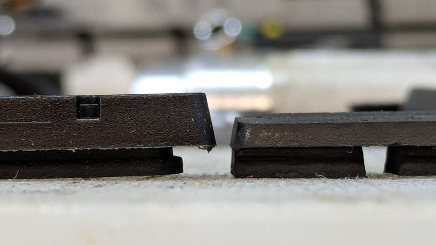
    The rear brake on my bike wasn’t stopping nearly as well as it should, even after cleaning the rim and pads with brake cleaner, so I pulled the shoes and replaced the pads:

    Bike brake pad wear
    Bike brake pad wear

    It’s down a bit beyond the --WEAR--LINE-- indicator, of course.

    New brake shoes on clean rims work exactly like they should!

  • Xubuntu 18.04 vs. VNC

    For unknown reasons, the Gnome-ish vino-server package for Xubuntu 18.04 no longer installs vino-preferences, so it’s not obvious how to configure the server.

    After considerable flailing, I installed good old x11vnc, set up a password, then started it in .xprofile:

    x11vnc -forever -find -no6 -avahi -usepw
    

    I don’t mind having programs change, but it’d be nice if features like, say, configuration wouldn’t just vanish.

  • Digital Tattoo Power Supply: Polarity Doesn’t Matter

    When I rewired the guts of the digital tattoo power supply to eliminate the series foot switch, I kept the original wiring polarity, with the black wire to the sleeve and the red wire to the tip:

    Tattoo Digital Power Supply - internal view
    Tattoo Digital Power Supply – internal view

    It’s the same color code I (strongly) recommend in the Squidwrench Electronics Workshops: use any color for the ground / common wire as long as it’s black, then, if you have a red wire, use it for the positive supply. You can use yellow for the higher supply voltage, but stop being clever.

    I put suitably colored Powerpoles on the far end of the cable to replace the standard tattoo machine spring clip connector, so I can attach clip leads, battery test fixtures, and so forth and so on.

    We wired the supply into a clip-leaded diode measurement setup with a current limiting resistor and a pair of multimeters to measure the diode current and forward voltage, whereupon we noticed all the meters displayed negative voltages and currents.

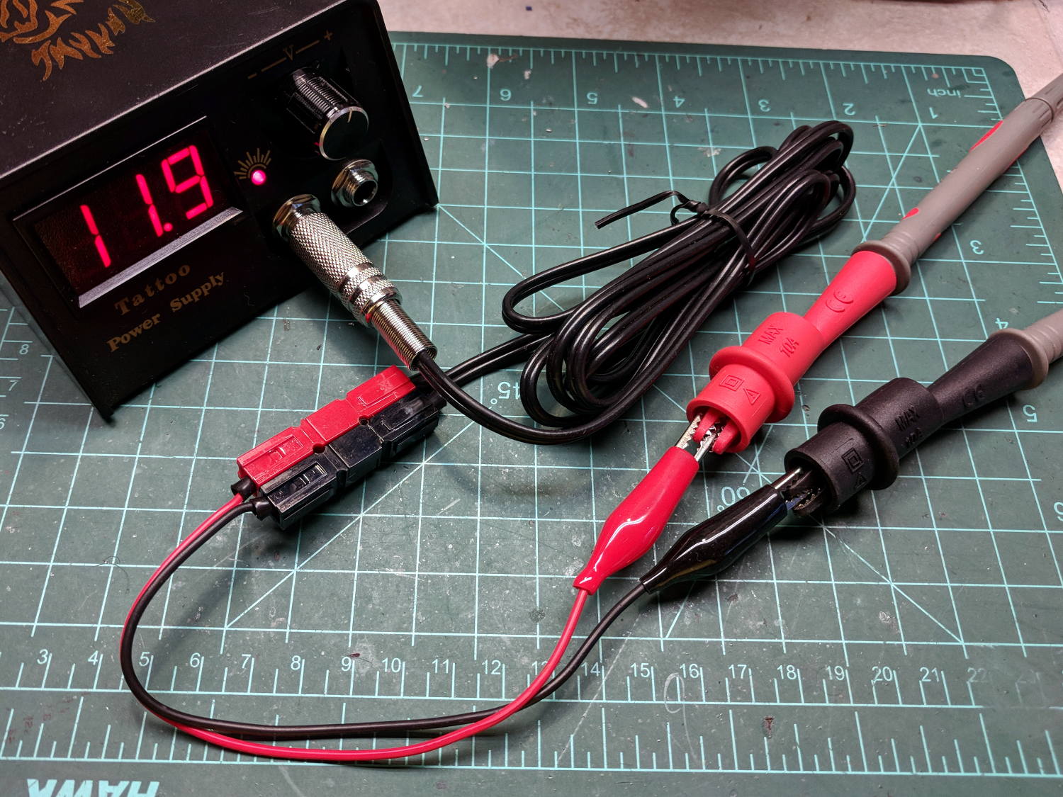
    After a frenzy of wire-checking verified their setup was all good, I forced the simplest possible test, herein recreated on my bench:

    Tattoo Digital Power Supply - polarity test
    Tattoo Digital Power Supply – polarity test

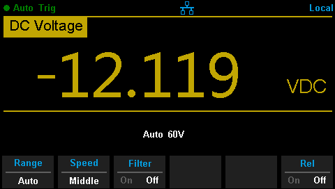
    Which produced this display:

    Tattoo Digital Supply - reverse polarity
    Tattoo Digital Supply – reverse polarity

    Huh.

    After a brief exploration of “Trust, but verify” territory, we swapped the clip leads from the power supply and continued the mission.

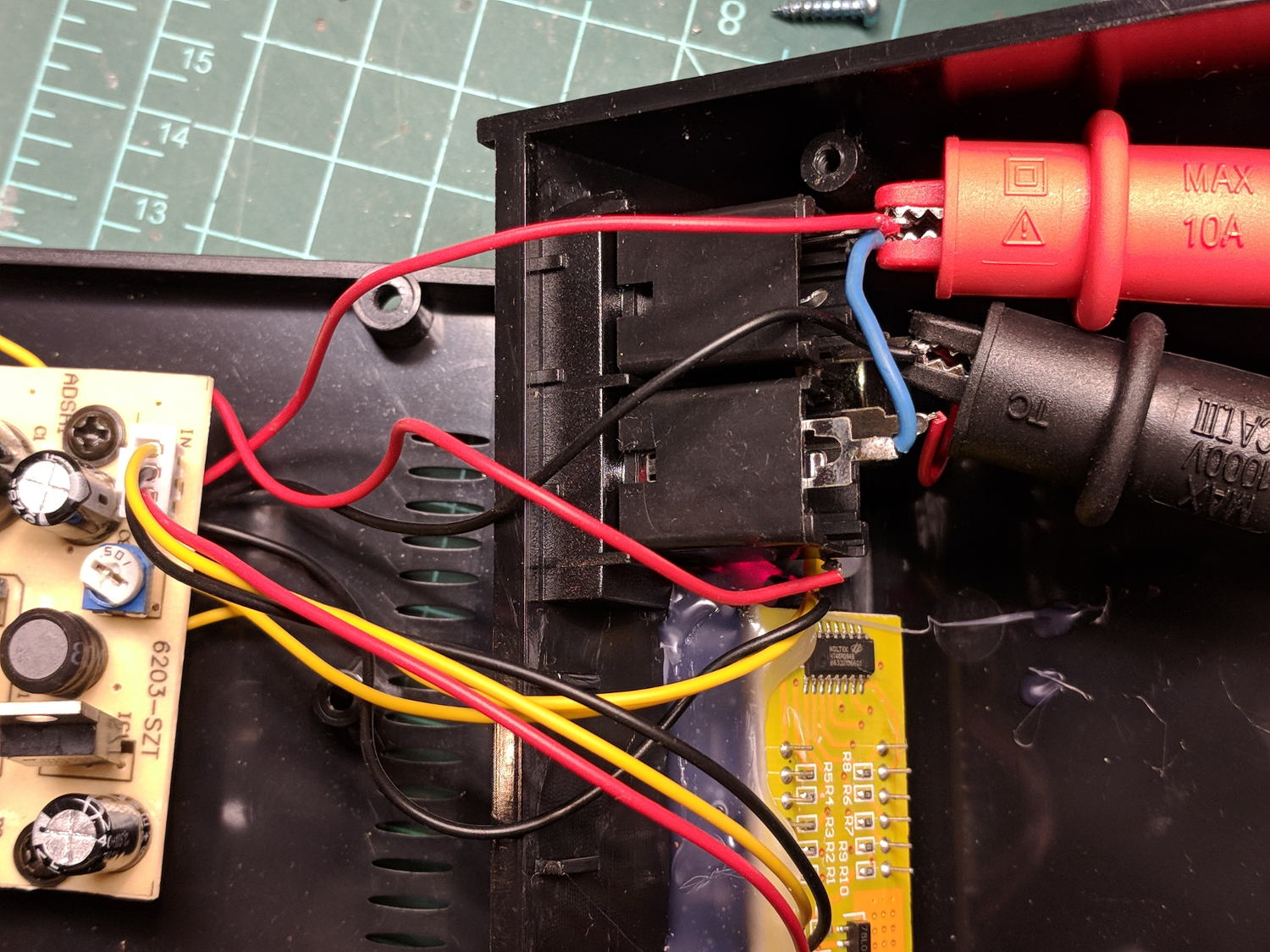
    Back on my bench, I pulled the supply apart and measured the voltage at the jack terminals:

    Tattoo Digital Power Supply - jack wiring
    Tattoo Digital Power Supply – jack wiring

    Still negative. Huh.

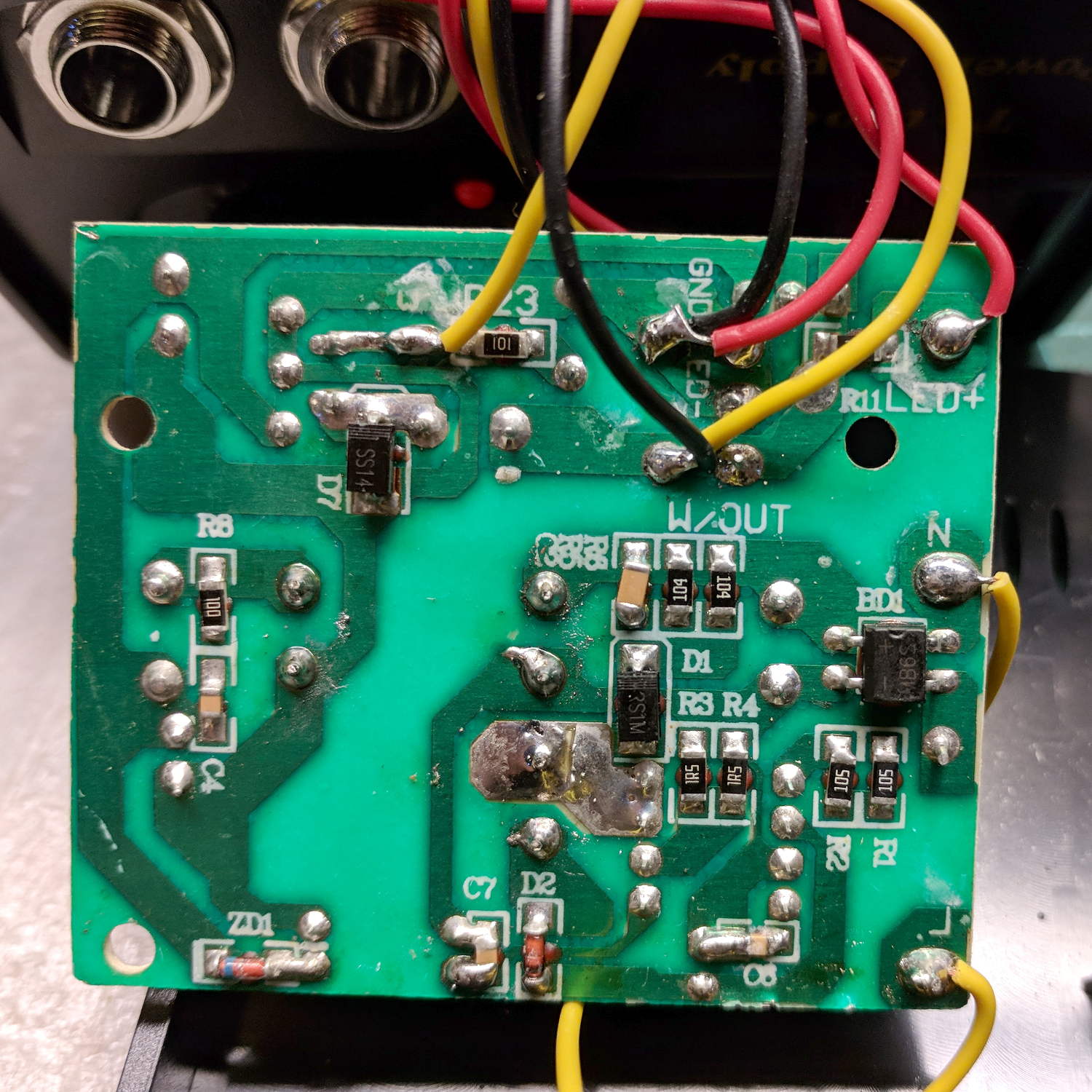
    The bottom of the power supply PCB shows exactly what you should expect by now:

    Tattoo Digital Power Supply - reversed color code
    Tattoo Digital Power Supply – reversed color code

    The red wire near the top of the board is, indeed, soldered to the trace labeled GND and goes to the jack’s tip terminal; the adjacent black wire goes to the front-panel LED. Similarly, the black wire just below it, soldered to the same trace as the yellow wire, goes to the jack’s sleeve terminal; that trace also connects to a resistor leading to the trace labeled LED+ and the LED’s red wire.

    Although tattoo machines run from DC supplies, their motors or vibrators don’t depend on any particular polarity and will run fine with a backwards supply.

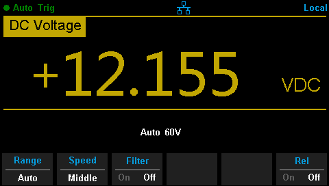
    Resoldering the red and black wires where they should go produces the expected sign at the jack:

    Tattoo Digital Supply - meter leads
    Tattoo Digital Supply – meter leads

    Although measuring and plotting diode voltages and currents may seem tedious, actually wiring stuff together and taking data reveals how difficult the real world can be.

    I trusted the supply’s internal color code and, although I’m certain I tested the Powerpoles, I obviously didn’t notice the meter’s sign.

    Memo to self: Sheesh.

  • Summer Downshift

    We have several high-intensity / long-attention-span home projects scheduled this summer, all of which will keep me away from the Basement Laboratory.

    We’re OK, all is right with our world, but painting rooms and yard maintenance always take way more time than they should, while having close to zero intellectual content.

    Like, for example, the result of a strenuous morning devoted to removing a severely overgrown holly bush:

    Mother of All Holly Bush Stumps
    Mother of All Holly Bush Stumps

    I’ll post odd & ends a few times a week until maybe mid-August, whereupon I should get back to more usual pursuits.

    Enjoy your downtime …

  • Tour Easy Front Derailleur Cable Clamp

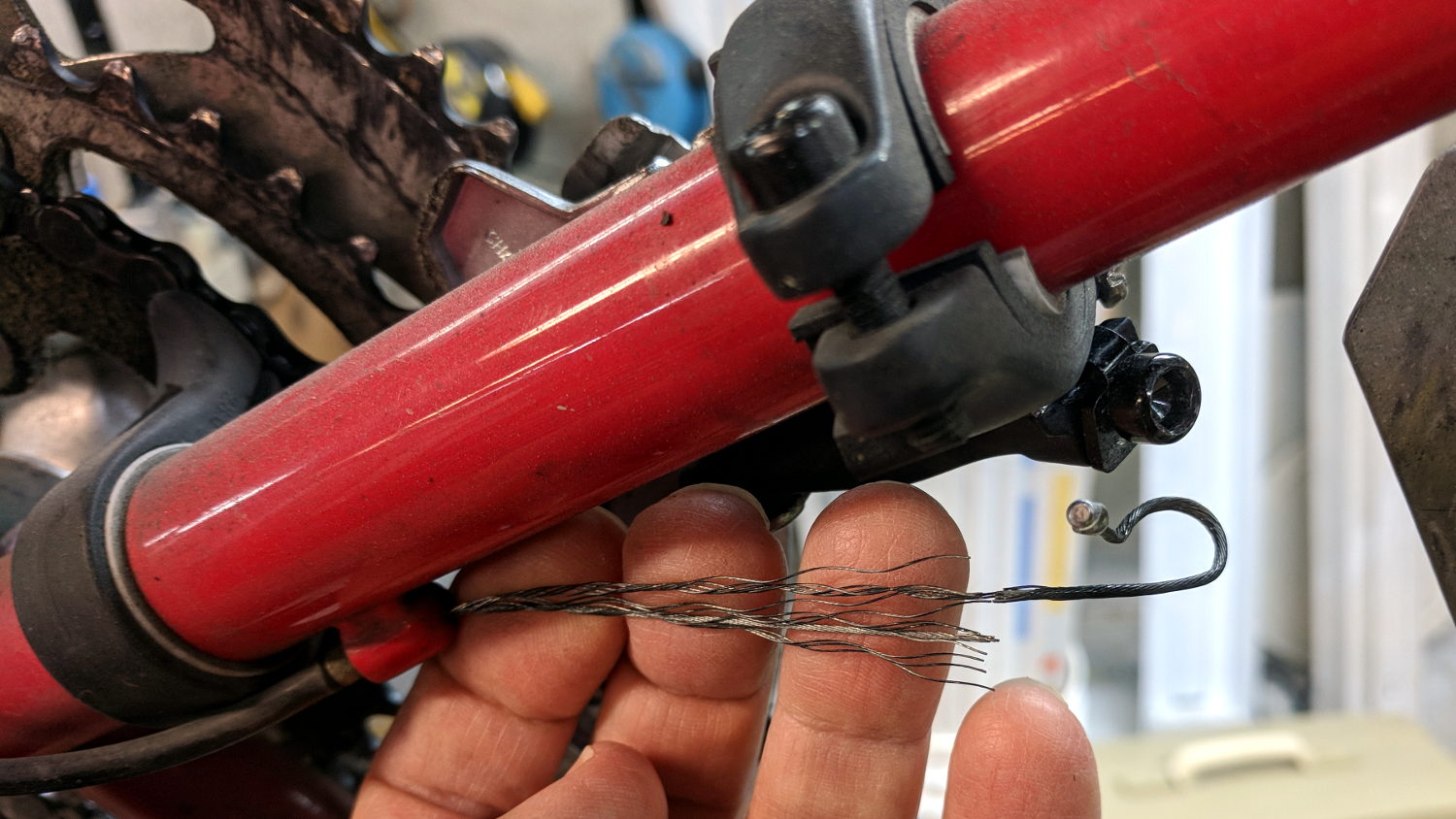
    In addition to sawing through the side of the cable ferrule, the front derailleur cable began breaking at the edge of the derailleur arm:

    Tour Easy Front Derailleur Cable - frayed
    Tour Easy Front Derailleur Cable – frayed

    It wouldn’t have survived another ride!

    Dan pointed out CNC machined aluminum cable clamps are a thing, but those are sized for larger frame tubes than the 1.0 inch steel used on our Tour Easy ‘bents and, although I’ve shimmed everything else on the frame, I wanted to tweak the cable angle to match the arm on the derailleur.

    A bit of OpenSCAD wrangling produces a likely candidate:

    Front Derailleur Cable Clamp - Slic3r
    Front Derailleur Cable Clamp – Slic3r

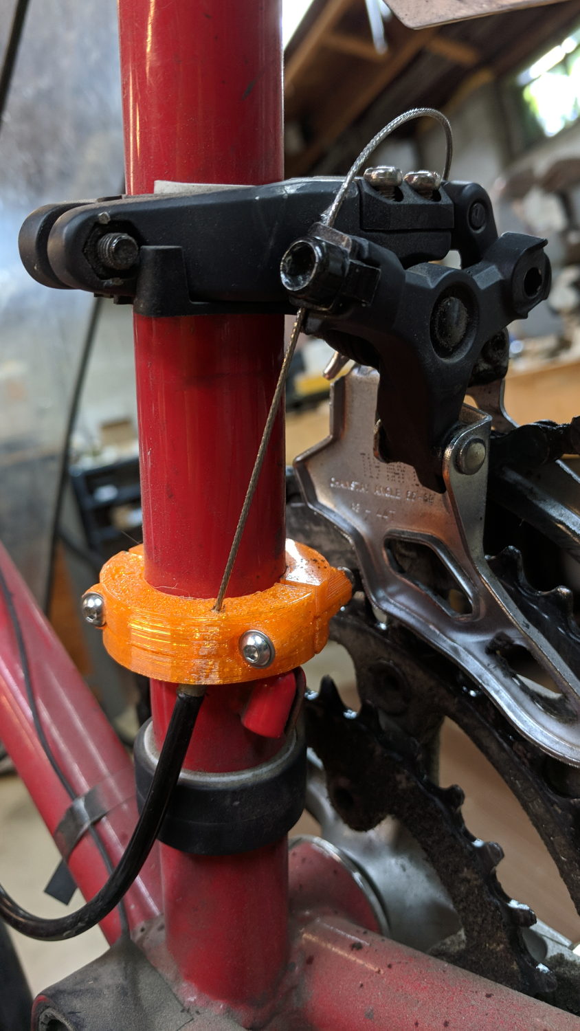
    That’s a bulked-up revision of the prototype:

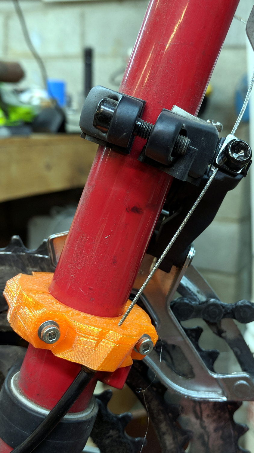
    Tour Easy Front Derailleur Cable Clamp - installed
    Tour Easy Front Derailleur Cable Clamp – installed

    Done up in orange PETG, it demonstrated the idea worked, but two perimeter threads wrapped around 15% infill isn’t quite up to the task. Note the split along the screw on the far half and various irregularities around the ferrule.

    The cable angle isn’t quite right, either, as the proper compound angle would, alas, aim the cable into the pedal crank. The bulky bushings get in the way of putting the ferrule where it should be with the screws aligned in a tidy manner, so I must get used to the jaunty angle.

    The bulkier version, done with 50% infill and four perimeter threads, has the same tilt angle, but the ferrule sits further from the screws:

    Tour Easy Front Derailleur Cable Clamp V2 - rear quarter view
    Tour Easy Front Derailleur Cable Clamp V2 – rear quarter view

    The view from the left side shows the cable angles slightly to the rear, but the smaller angle should make it happier:

    Tour Easy Front Derailleur Cable Clamp V2 - side view
    Tour Easy Front Derailleur Cable Clamp V2 – side view

    Probably should have used black PETG. Next time, for sure!

    The OpenSCAD source code as a GitHub Gist:

    // Tour Easy Derailleur Cable Clamp
    // Ed Nisley KE4ZNU – June 2017
    /* [Build Options] */
    Layout = "Build"; // [Build, Show]
    /* [Extrusion] */
    ThreadThick = 0.25; // [0.20, 0.25]
    ThreadWidth = 0.40; // [0.40]
    function IntegerMultiple(Size,Unit) = Unit * ceil(Size / Unit);
    /* [Hidden] */
    Protrusion = 0.01; // [0.01, 0.1]
    HoleWindage = 0.2;
    ID = 0;
    OD = 1;
    LENGTH = 2;
    /* [Cable Clamp] */
    FrameOD = 25.7; // Tour Easy has hard inch tubing + paint
    Ferrule = [1.5,5.1,12.0]; // cable ferrule
    EntryPoint = [0,13,60]; // cable entry to derailleur, +Y to rear of bike
    CableTilt = -20; // tilt from parallel to frame tube
    CableTheta = 0; // rotation around clamp from +X axis
    /* [Screws and Inserts] */
    ClampScrew = [3.0,5.5,35.0]; // M3 button / socket head cap screw
    ClampWasher = [3.7,7.0,0.7]; // M3 washer
    ClampNut = [3.0,6.0,4.0]; // M3 nylock nut
    /*
    ClampScrew = [4.0,7.0,25.0]; // M4 button head cap screw
    ClampWasher = [4.5,9.0,0.8]; // M4 washer
    ClampNut = [4.0,8.0,5.0]; // M4 nylock nut
    */
    NutShift = -0; // slide bushing toward nut for clearance
    //- Set clamp ring dimensions
    WallThick = 10.0;
    BushingSides = 8;
    Bushing = [ClampScrew[ID],
    // ClampWasher[OD]/cos(180/8) + 4*ThreadWidth,
    Ferrule[LENGTH]/cos(180/BushingSides),
    ClampScrew[LENGTH] – 2*ClampWasher[LENGTH] – ClampNut[LENGTH]];
    Ring = [FrameOD + HoleWindage,FrameOD + 2*WallThick,Ferrule[LENGTH]];
    ClampScrewOC = IntegerMultiple(FrameOD + ClampWasher[OD],1);
    echo(str(" screw OC: ",ClampScrewOC));
    ClampKerf = 0.75; // kerf between separated halves
    NumSides = 8*4;
    //- Adjust hole diameter to make the size come out right
    module PolyCyl(Dia,Height,ForceSides=0) { // based on nophead's polyholes
    Sides = (ForceSides != 0) ? ForceSides : (ceil(Dia) + 2);
    FixDia = Dia / cos(180/Sides);
    cylinder(r=(FixDia + HoleWindage)/2,h=Height,$fn=Sides);
    }
    // Construct things
    module ClampRing() {
    difference() {
    union() {
    cylinder(d=Ring[OD],h=Ring[LENGTH],$fn=NumSides); // basic ring
    for (j=[-1,1]) // screw bushings
    translate([Bushing[LENGTH]/2 + NutShift,j*ClampScrewOC/2,Ring[LENGTH]/2])
    rotate([0,-90,0]) rotate(180/BushingSides)
    cylinder(d=Bushing[OD],h=Bushing[LENGTH],$fn=BushingSides);
    intersection() {
    rotate([CableTilt,0,CableTheta]) // reinforce cable ferrule
    translate([(Ring[ID] + Ring[OD])/4,0,Ferrule[LENGTH]/2])
    rotate(180/8)
    cylinder(d=3*Ferrule[OD] + 0*ThreadWidth,2*Ferrule[LENGTH],center=true,$fn=8);
    cylinder(d=2*Ring[OD],h=Ring[LENGTH],$fn=NumSides); // basic ring
    }
    }
    translate([0,0,-Protrusion]) // frame tube
    cylinder(d=Ring[ID],h=Ring[LENGTH] + 2*Protrusion,$fn=NumSides);
    rotate([CableTilt,0,CableTheta]) // cable ferrule
    translate([(Ring[ID] + Ring[OD])/4,0,-0.25*Ferrule[LENGTH]]) {
    rotate(180/8)
    PolyCyl(Ferrule[OD],Ferrule[LENGTH],8);
    rotate(-22.5)
    PolyCyl(Ferrule[ID],2*Ferrule[LENGTH],4);
    }
    for (j=[-1,1]) // screw holes
    translate([Ring[OD]/2,j*ClampScrewOC/2,Ring[LENGTH]/2])
    rotate([0,-90,0]) rotate(180/6)
    PolyCyl(Bushing[ID],Ring[OD],6);
    for (i=[-1,1], j=[-1,1]) // screw & nut seats
    translate([i*(Bushing[LENGTH]/2) + NutShift,j*ClampScrewOC/2,Ring[LENGTH]/2])
    rotate([0,i*90,0]) rotate(180/BushingSides)
    cylinder(d=Bushing[OD],h=Bushing[LENGTH],$fn=BushingSides);
    translate([0,0,Ring[LENGTH]/2]) // slice it apart
    cube([ClampKerf,2*Ring[OD],2*Ring[LENGTH]],center=true);
    }
    }
    //- Build things
    if (Layout == "Show") {
    translate(EntryPoint)
    cube(1,center=true);
    ClampRing();
    }
    if (Layout == "Build") {
    ClampRing();
    }
  • Tour Easy: Front Derailleur Cable Angle

    Spotted while in the midst of replacing my Tour Easy’s rear grip shifter:

    Tour Easy - front derailleur cable angle
    Tour Easy – front derailleur cable angle

    As you might expect, the cable saws through the side of its ferrule and the brazed-on frame fitting, because it’s been basically impossible (for me, anyhow) to find a replacement derailleur duplicating whatever the good folks at Easy Racers shipped back in 2001.

    On the upside, this derailleur’s cable entry has a nicely rounded ramp eliminating the need for my brass cable pulley widget.

    Memo to Self: Perhaps running the cable around a bearing anchored to the frame fitting would help?

    I’ve obviously forgotten to fix this for several years, so putting it here may serve as a Round Tuit.

  • Primo Comet vs. Green Glass Chip: Kevlar FTW!

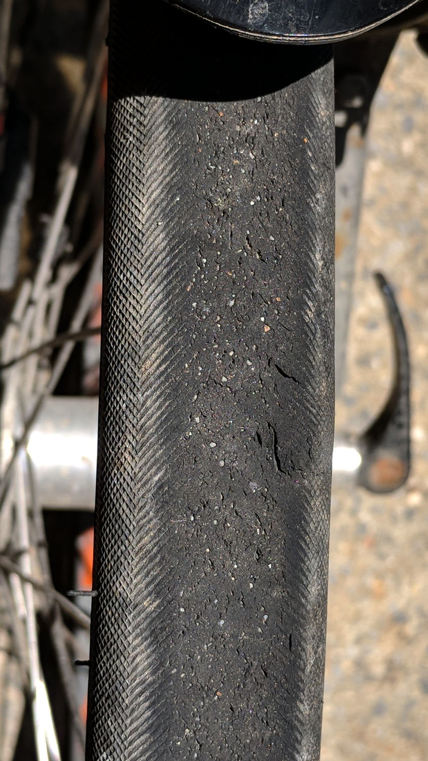
    The gashes don’t look like much:

    Primo Comet gash - tread view
    Primo Comet gash – tread view

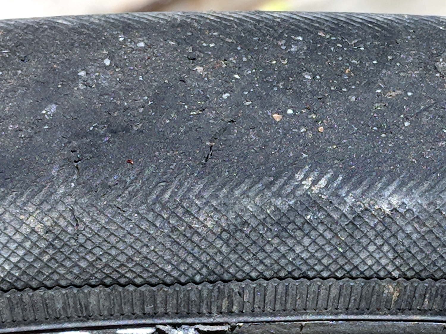
    Not even from the side:

    Primo Comet gash - side view
    Primo Comet gash – side view

    When they happened, I knew where to look, because the Kevlar-belted Primo Comet had two conspicuous bulges surrounding debris jammed between the tread and the carcass along the sidewall: the gashes were wide open!

    Much to my astonishment, the tire hadn’t gone instantly flat.

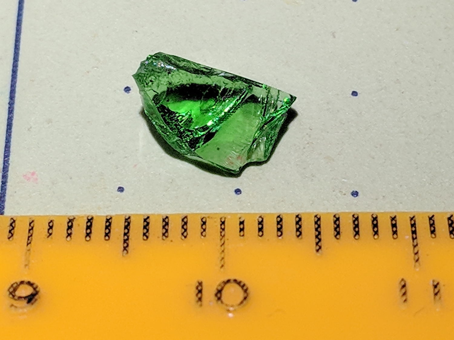
    Some screwdriver probing in the leftmost gash produced this nasty glass chip:

    Primo Comet gash - chip side view
    Primo Comet gash – chip side view

    AFAICT, the smooth side slid over the internal Kevlar belt as the edge sliced between the rubber tread and the carcass. I think the top entered first, with the somewhat crushed end hitting the pavement on each revolution:

    Primo Comet gash - chip edge view
    Primo Comet gash – chip edge view

    The other gash emitted a somewhat smaller chip.

    I rode over something crunchy, most likely the remains of a beer bottle, in a shaded section along Rt 376, and we stopped a few driveways later to diagnose a once-per-revolution thump from the front tire. The tube still wasn’t losing pressure, even after extracting the glass, so I continued the mission; it was a fine day for a ride!

    I later filled those gashes (plus a few others) with silicone rubber to keep grit out. It’s surely a feel-good gesture, but maybe it’ll help the tire reach the end of its tread life.

    You can judge our “riding environment” by the tire’s condition …